Archive for the ‘sheet aluminum’ Tag
I did some measuring today and discovered the adjustable seat rails raise the seat too high for mounting in the enclosed cockpit – on a Roadster, an open car – this would not be a problem, and may help shorter drivers (under 6-foot) like me.
Stay tuned for an update as I re-modify the mounts by installing the rails on the side of the seat – as mentioned in the earlier post. Scroll to the entry by ChazC5ZX.
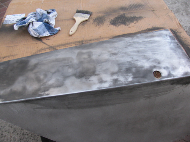
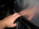
Last weekend, I decided to get back to work on the Coupe. I have to focus on getting everything ready for the engine installation. So, I started to mount the previously painted foot box aluminum.
But I ran into a problem – the oily under body paint was not adhering well in some places, and the paint surface quality varied greatly. Here is a picture of what I mean…

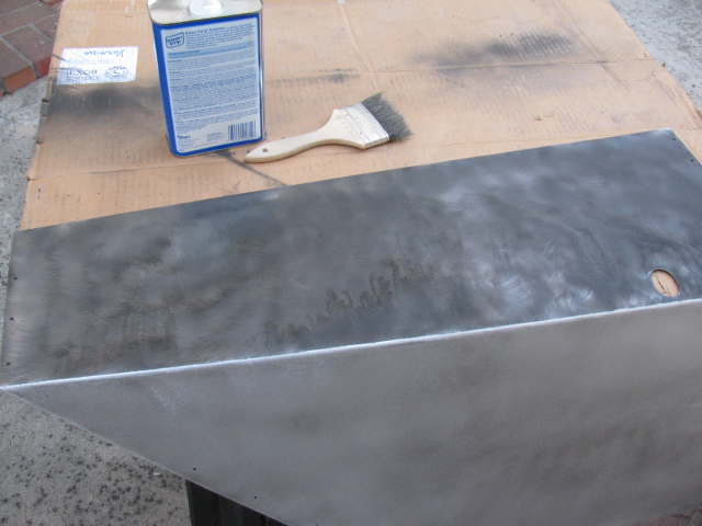
Rather than just leaving it alone, I decided to remove all undercoated parts and re-finish them with truck bed liner paint. The truck bed liner paint is more consistent, is very hard and seems to adhere better than the under body paint.
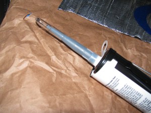
Taking off the greasy under coating was difficult, because the gooey paint clogged up the abrasive pads on my random orbit sander. So, I had to first use a wire brush on my drill to “scrape” off the greasy stuff, and then wash it down with acetone, like this:


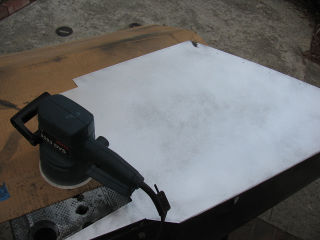
… and then sanded to bare metal with a 60 grit disc on my random orbit sander.

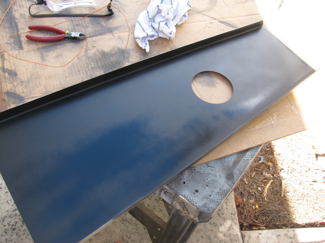
I washed the panels with dish washing liquid in my kitchen sink, and applied two coats of truck bed liner paint. Now the panels look much better. The truck bed paint has a slight wrinkle finish so I am not sure how hard this will be to keep clean. It is, however, better than that greasy under coating stuff. Here is a picture of the bottom surface of the transmission tunnel cover.

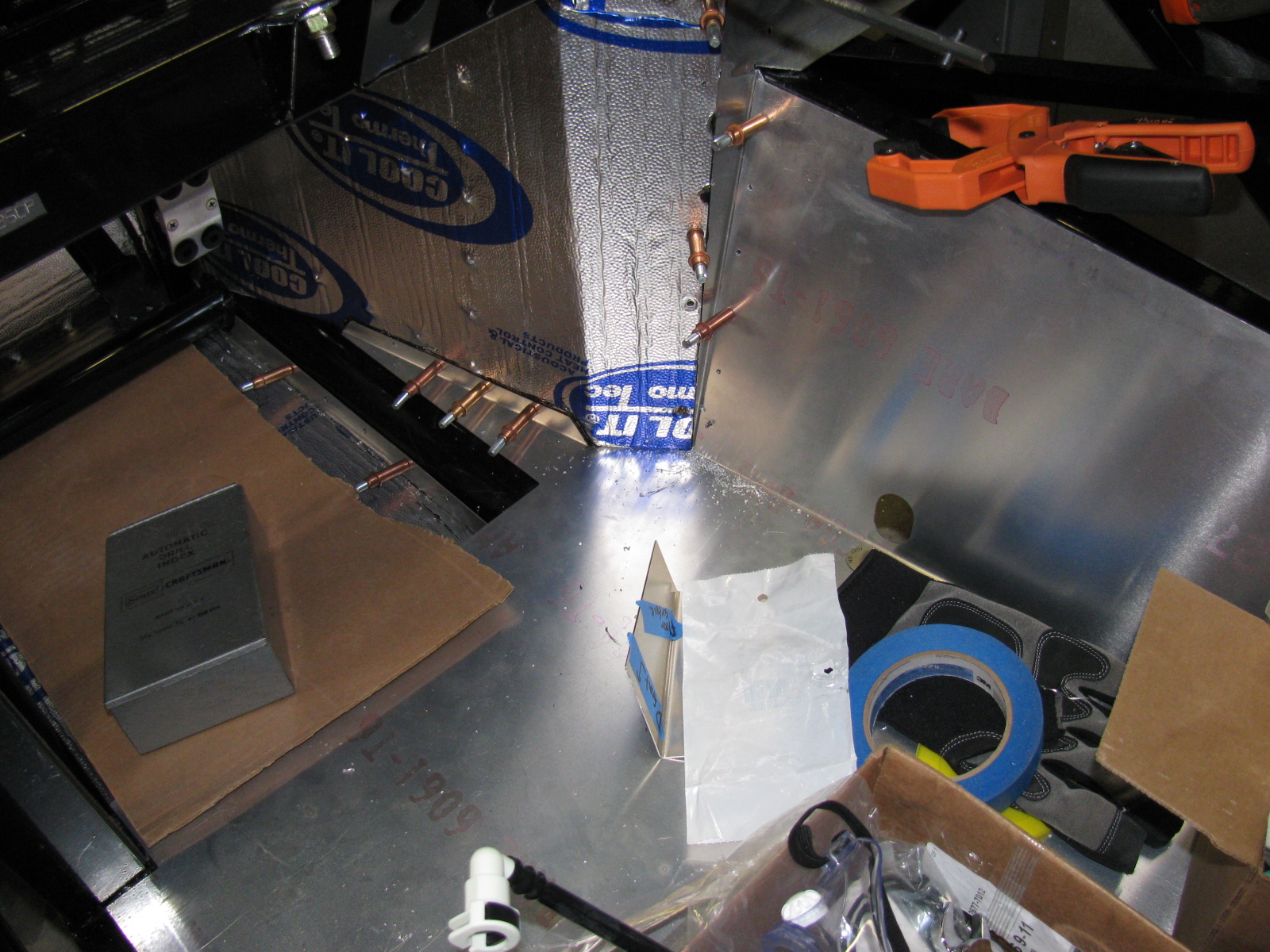
I will cover all interior surfaces with heat and sound barrier (Cool-It) and then put carpet over everything later.
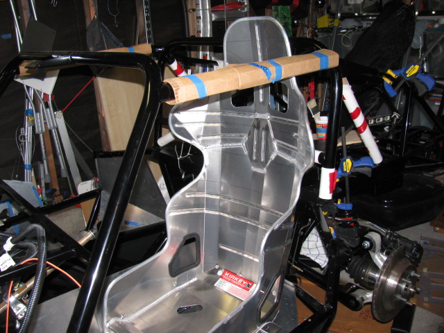
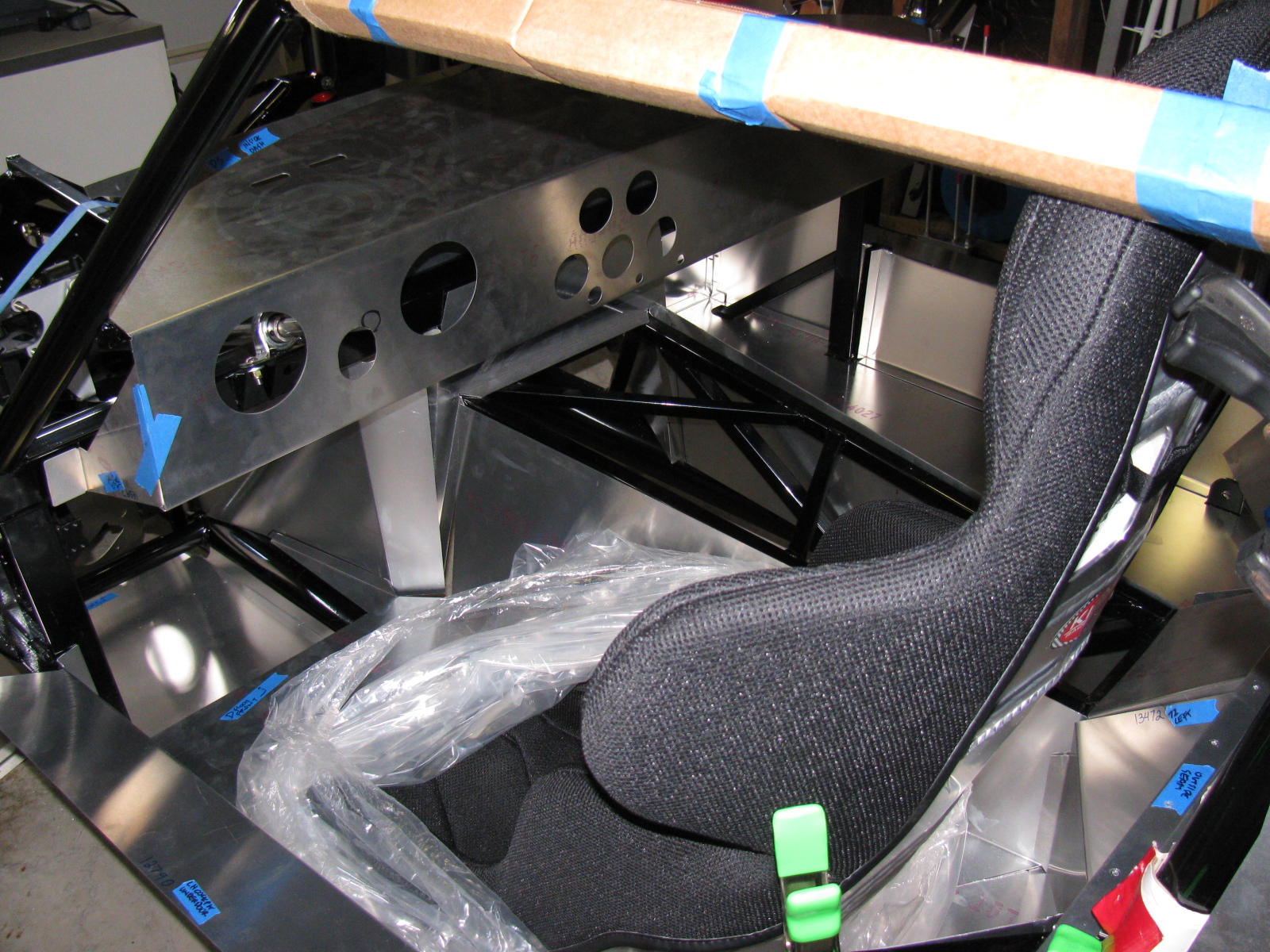
Since I am working on cockpit “fitment,” I wanted to dry-fit the Kirkey high back racing seats so I can adjust the position for pedal actuation.
The Factory Five Racing Complete Kit provides two options for seats, low-backs for the more traditional look, and a high back option that provides more back support. I went with the high backs. However, the seats come with nuts and bolts, and the instructions say to drill the seats and use the bolts to attach them to the floor.
I checked the forums and found a better solution. Thanks to posts by Rich A and rick8928, I copied what they did with their seat mounts. Their solution adds an adjustment feature to the seat mounts. The part numbers from Summit are still valid, although the prices have gone up a little. I bought two sets so the passenger seat will be adjustable, too. Thanks guys for helping me to not re-invent the wheel on this one!
Here are some pictures of my version…


The last two images above show the seat belt mounting points.
Here is a cockpit view of the pedal box.

I am glad I have the seat adjusters, it should make getting in and out of the car easier. It looks like I will have to adjust the seat forward in order to reach the pedals comfortably, and then I can push the seat back to get out (and in) the car.
Heel-toe should be okay, I will have to bolt the seats into the car and move the seat forward to make sure.

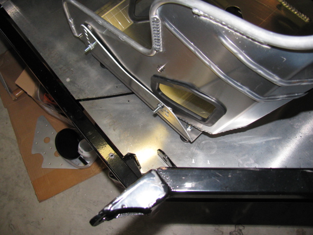
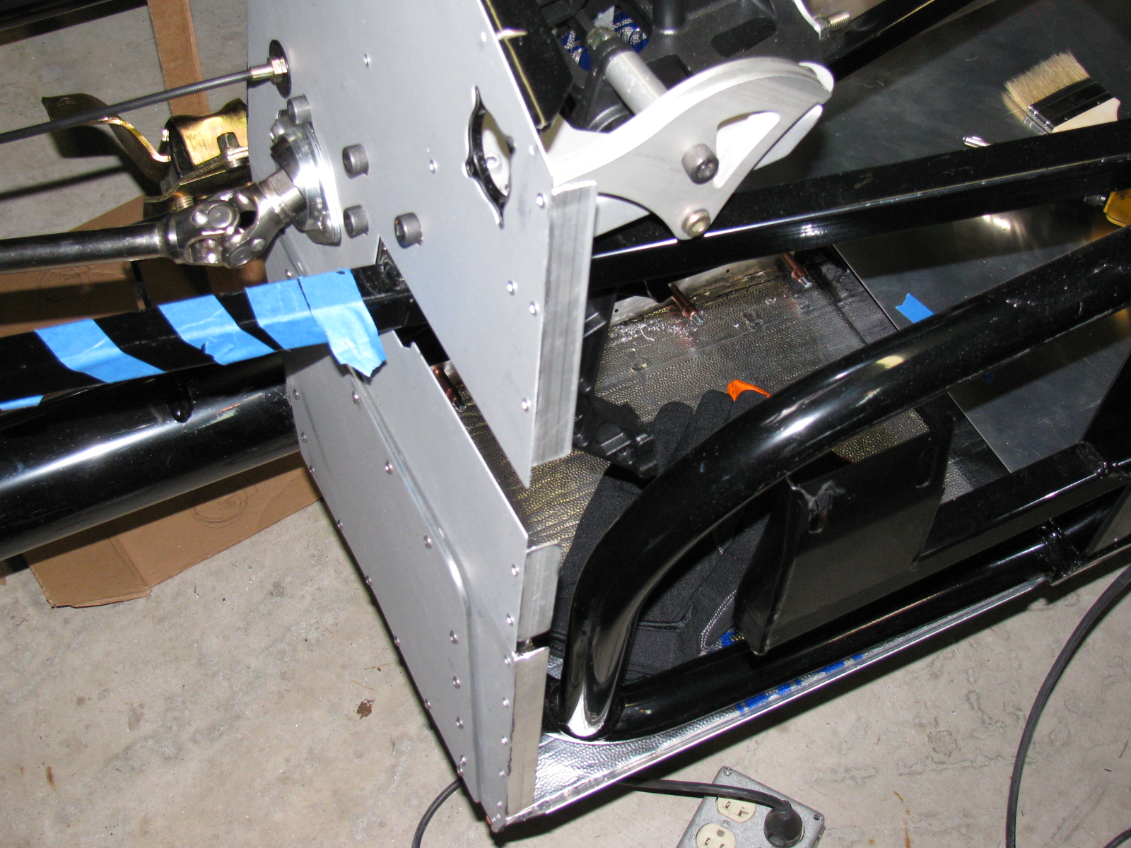
Sharp-eyed viewers noticed the left side of the driver foot box is missing. Indeed it is. I made a small modification to this part – I cut the tabs off of the mating panel, and added small angle aluminum to the front piece, so I can rivet (maybe screw in) this panel later.

I should probably do the same thing to the right side of the pedal box, so I can access the gas pedal mounts for adjustment, although the engine might be in the way.
Stay tuned, more to come on the Factory Five Racing Type 65 Coupe Project.

After several weeks, it is good to get back to work on the Factory Five Racing Type 65 Coupe. I finally completed drilling the rivet holes for all cockpit aluminum panels, and added a battery cut-off switch as you can see above.
Here is a hint for builders – there is a fairly large gap in the bottom right corner of the driver’s side floor and the “A” shaped piece that meets the transmission tunnel. I looked at several Coupes and Roadsters and they all have this space. However, by pushing on the A-shaped piece from behind (under the chassis and in the engine bay) – this gap can be closed up nicely. See below. . .


But what about this area, at the rear of the driver’s side door – indicated by a piece of blue masking tape – see that gap? Does something cover this space up or do I need to fabricate a replacement panel? Both sides look the same.

As mentioned in a previous post, I finally decided to mount the external fuel pump under the Factory Five Metal battery box. This is a protected location and is a low point on the chassis.

One problem will be access to the fill and drain holes for the Ford Racing differential. I had to drill out the rivets previously installed and tapped some 1/4-20 holes – this will enable the removal of the battery box when draining and filling the rear end fluid. Not the ideal situation, but I do not see too many alternatives to this arrangement.
My Ford 302 V8 has an MSD Atomic electronic fuel injection system, and I am running both feed and return fuel lines. Here is a picture of the tank end. . .

The fuel line runs from the first filter (right side of the chassis) to the fuel pump, and goes around to the driver side. Then it goes under the rear end to the passenger side of the chassis, where it goes to a second fuel filter mounted under the passenger seat, and finally to the engine.
The same path will be used for the return system. Pretty much standard layout.
Next Build Session
Depending on the weather, I will remove all interior panels and paint the under side with automotive under body paint. It is a rubberized black paint which should deaden some road noise, insulate heat and protect the panels from road debris.
Another item on the next to do list is the wiring harness. Here is a look at the main portion. . .

. . . and a BBQ Dessert Experiment
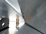
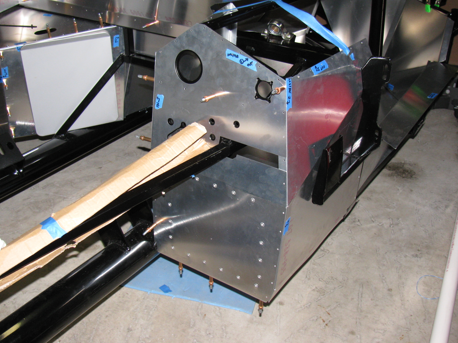
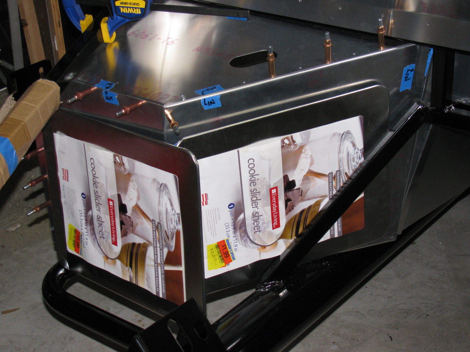
Work on the passenger and driver side foot boxes continues on the Factory Five Racing Type 65 Coupe.
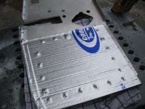
I painted the engine side of the panels with silver BBQ paint, and left the interior side un-painted, since all panels will be covered with Cool-It heat and sound barrier. Panels that face the exterior of the car – like the foot box floors and the trunk area, will be painted with RustOleum truck bed liner. It is a textured black finish that will also help reduce sound and noise. Here are some images. ..


On the left is a detail of one of the cookie sheet heat shields, fastened to the firewall with 8-32 riv-nuts. The spacing is about one-quarter-inch. On the right is a view of the top of the heat shield, showing the nicely rolled edge.


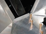
Passenger side foot box appears on the left of the photo above. The photo on the right shows a closer look at the passenger foot box.


Photos above: Passenger foot box, before and after installing the Cool-It mats.


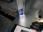
Above left: The top seam on the passenger foot box – this will be either trimmed or a strip of aluminum will be used to cover the mis-match. On the right, I added srtips of aluminum angle to the outer wall of the driver side foor box. This should make the outer wall easier to install.
The next series of photos show how the interior panels go into place. The un-finished aluminum is difficult to photograph, I wish the manual would include an exploded view of the panels and how they fit into place. This is a complex jigsaw puzzle, and many of the parts must be flexed, trimmed and pulled into place. Clecos really help. This is one area where the manual offers good advice – the sections fit best when you follow the order outlined in the manual. Although many of the panels are marked with a part number, they do not indicate the orientation of the panel.
The foot box floors were very difficult to fit into place, so I sliced them into sections. If you look carefully you can see the saw kerfs (seams) on the floor panels. I chose the cuts carefully, in order to make sure I would have something solid to rivet to. In the areas without any supporting chassis tubes, I will install strips of aluminum bar stock.
The panels will be permanently attached later with silicone adhesive and rivets – at this stage, the panels are being “dry-fitted” with clecos to make sure everything is properly in place.


Somewhere during this building session, I made some time to pack my hot giardiniera into jars, and made a few deliveries. . .
I also managed to do some BBQ experiments. This time I baked some apple turn-overs in the Big Green Egg. They turned out OK, but could be better. They are like just-right bites of apple pie. Here are some pictures. . .


It’s been a few weeks since I posted an update. Some people have been asking for some news, so here we go. . .
I am preparing the chassis so I can install the engine and transmission. This means that I have to finish the firewall, which means prepping and painting the foot boxes and routing and mounting the brake and fuel lines.
I decided to finish the engine bay with silver Rust-Oleum high temperature BBQ paint. This is a change from my thoughts on powder coating and appliance epoxy. . . The appliance epoxy has an upper temperature limit of 200 degrees F, and I think engine bay heat is higher than an oven. The BBQ paint is good for 1200 degrees F or something like that. Depending on how the engine bay looks, I may strip everything off and re-finish with powder coat later. But for now, the silver BBQ paint looks OK. The nice weather last week allowed me to do some rattle-can spraying outside.
I permanently mounted my first aluminum panel – the driver’s side foot box front. I am using Permatex Ultra Black number 2105 silicone adhesive. This is what Kirkham Motors uses for their builds, so I will use what they use. It can be used as an adhesive as well as a gasket, so this extends its usefulness around the shop.
References: Kirkham online build and Permatex Ultra Black goop


Above right is a close-up of the BBQ paint finish on one of the pedal box panels. Looks OK. There is a slight texture to the finish. The color is actually silver, the blue-ish tint is probably from sunlight diffracting from somewhere.

Above left, a “dry fit” of the driver side foot box front panel. You can see the cookie sheet heat shields in place. Above right, using the panel as a pattern to cut the insulation mat – just place the panel onto the backing side of the mat, press down and then cut with shears or a knife. Final trimming is done with a utility knife.
Cool-It heat and sound insulation is applied to the interior side of the foot box panel. The “bubbles” you see are from the riv-nuts and screws poking out from the other side. On the right, I wanted to make sure the adhesive stuck properly at the top of the panel, so I used some clamps to squeeze evenly. My good friend Norm Abram always says, “You can never have too many clamps.”
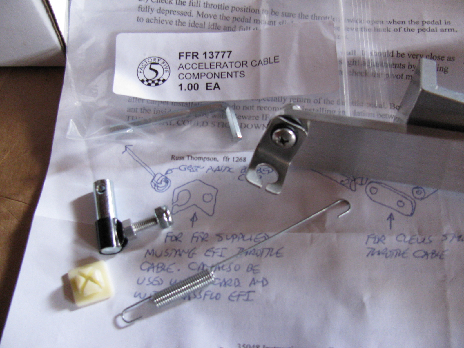
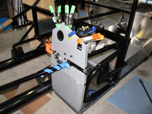
The Accelerator Cable and Pedal
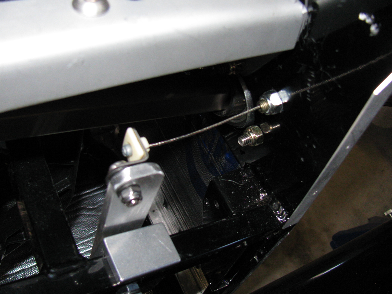
I mounted the accelerator cable as well as the Russ Thompson gas pedal, sold by Breeze Automotive. The instructions are different from what is being supplied by Factory Five Racing now. (I am getting used to this. . . )

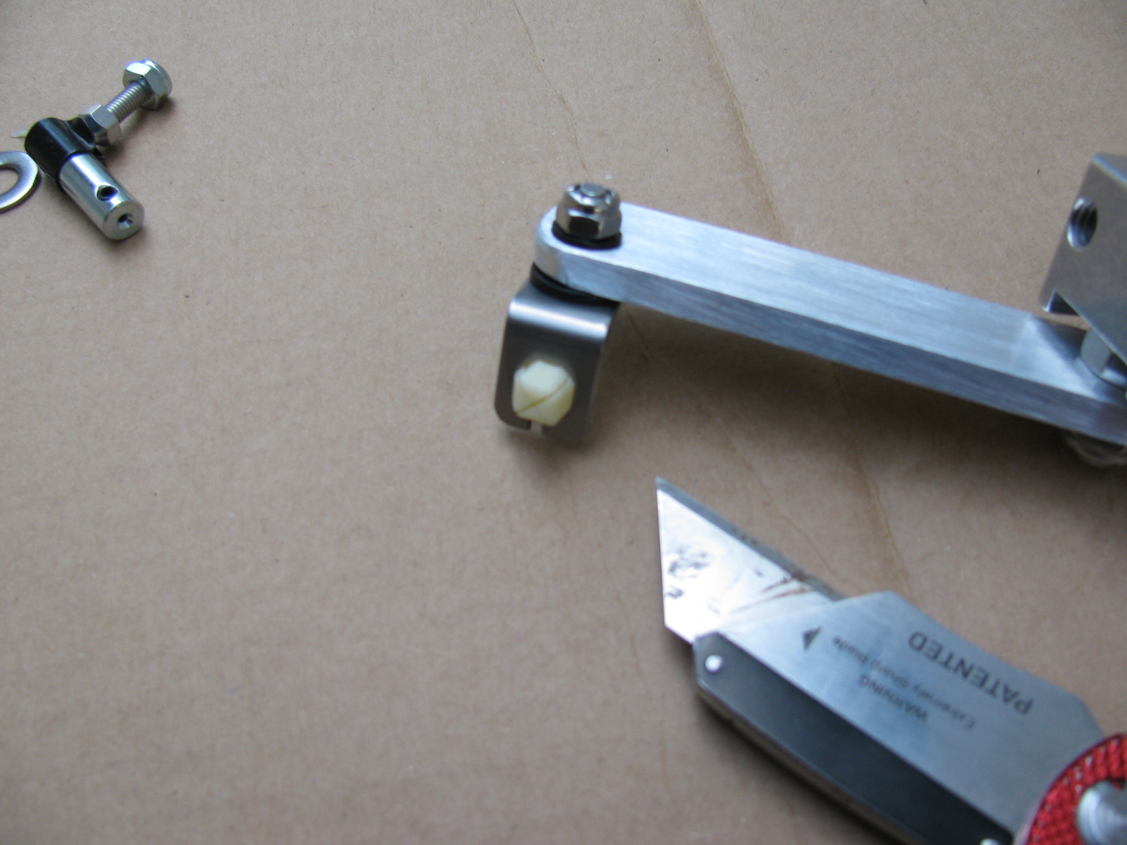
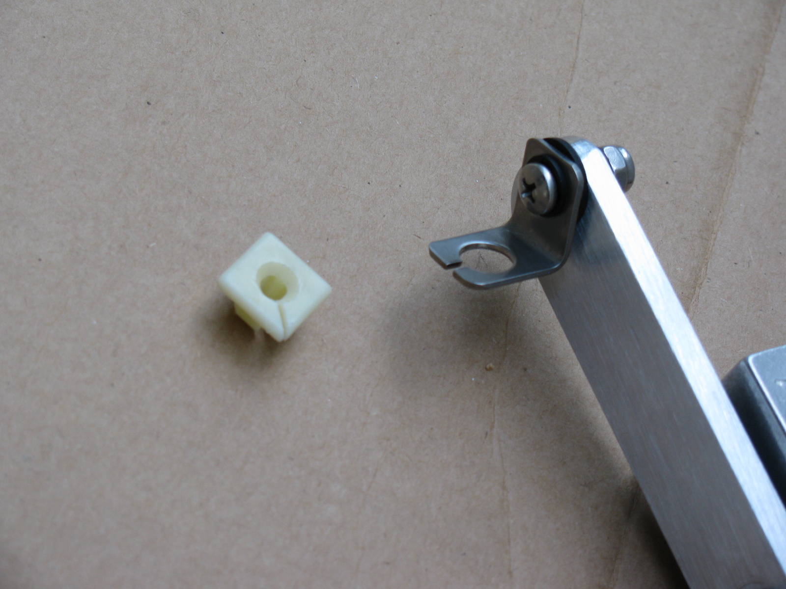
The picture above shows some of the gas pedal mounting parts that come with the Complete Kit. The Thompson / Breeze pedal instructions say something about a “green plastic barbed clip” at the end of the throttle cable. This green thing is no longer what comes with the kit. Instead, there is a little square “plug” that is too big to fit into the pedal mount.
Rather than cutting off the ball-end at the throttle cable or drill a bigger hole in the mount, I decided to carefully cut some of the plastic from the center barb so it would fit snugly into the mounting hole – not much has to be shaved off, it is something like a sixteenth of an inch or so. Then I made a slit in the square plastic thing as shown so the cable could slip in with the ball intact.


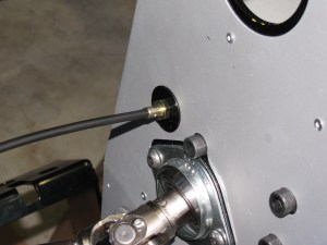
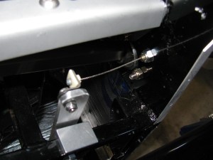
As you can see above, I added a fender washer (painted black) to the throttle cable mounting point, this is just for looks.
This is Irritating
For some reason, this bothered me today, but then I realized not many tubes of caulk gun goop come with caps. Anyway, I used a pen cap to close the tube. I hope this works, I only needed a few beads for this build session.
Some Great Looking Door Panels on Order!
I ordered a set of leather door panels from Levy Racing earlier this week. They look like this:

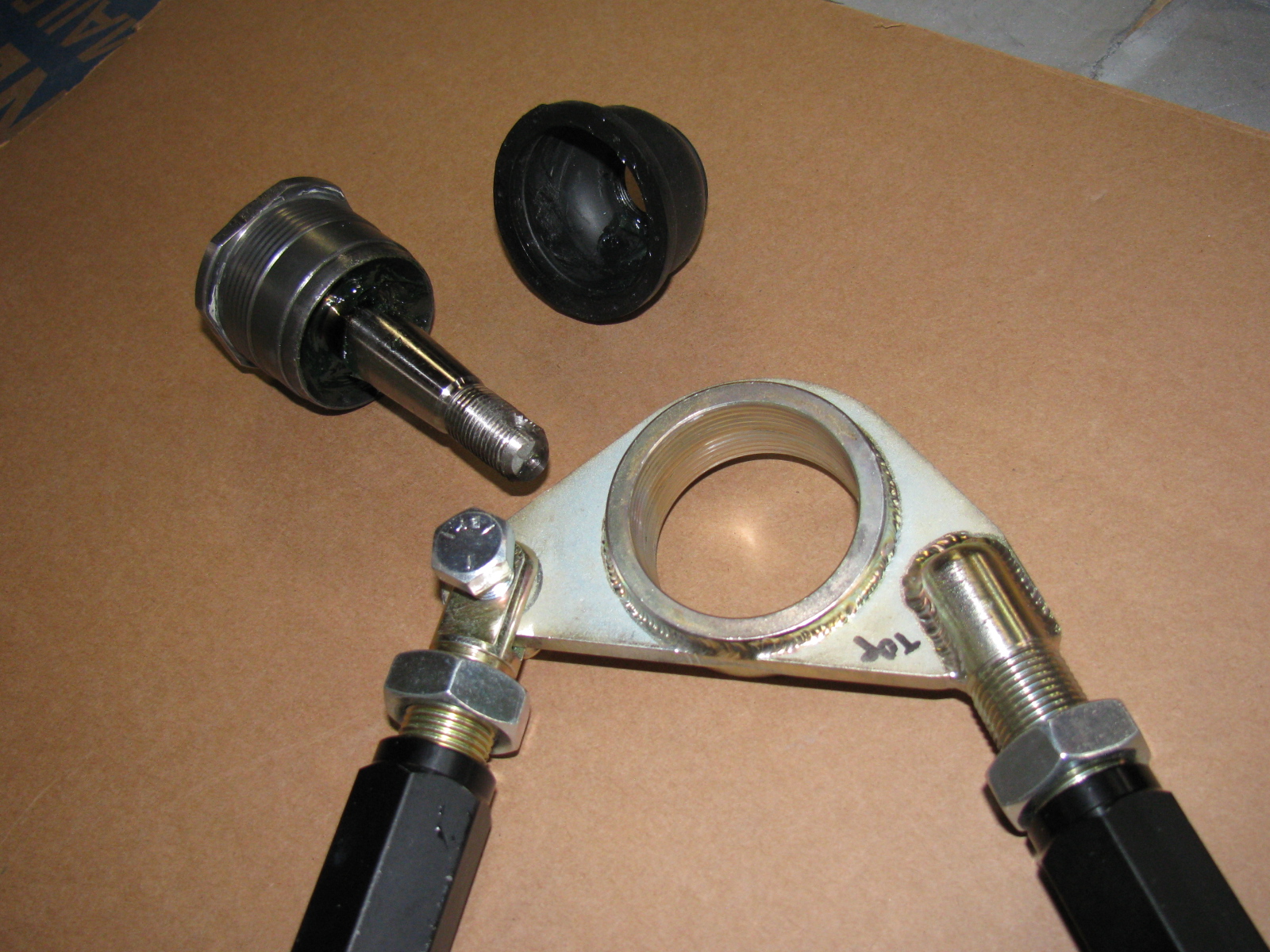
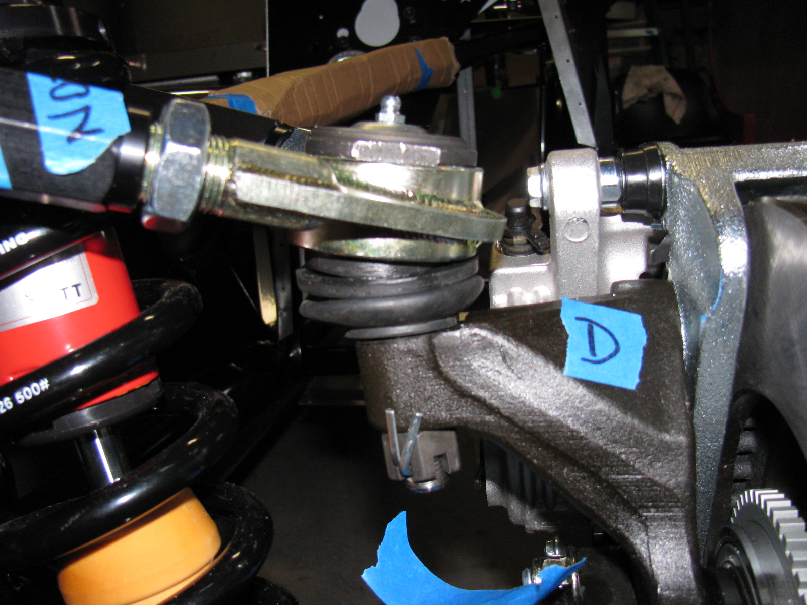
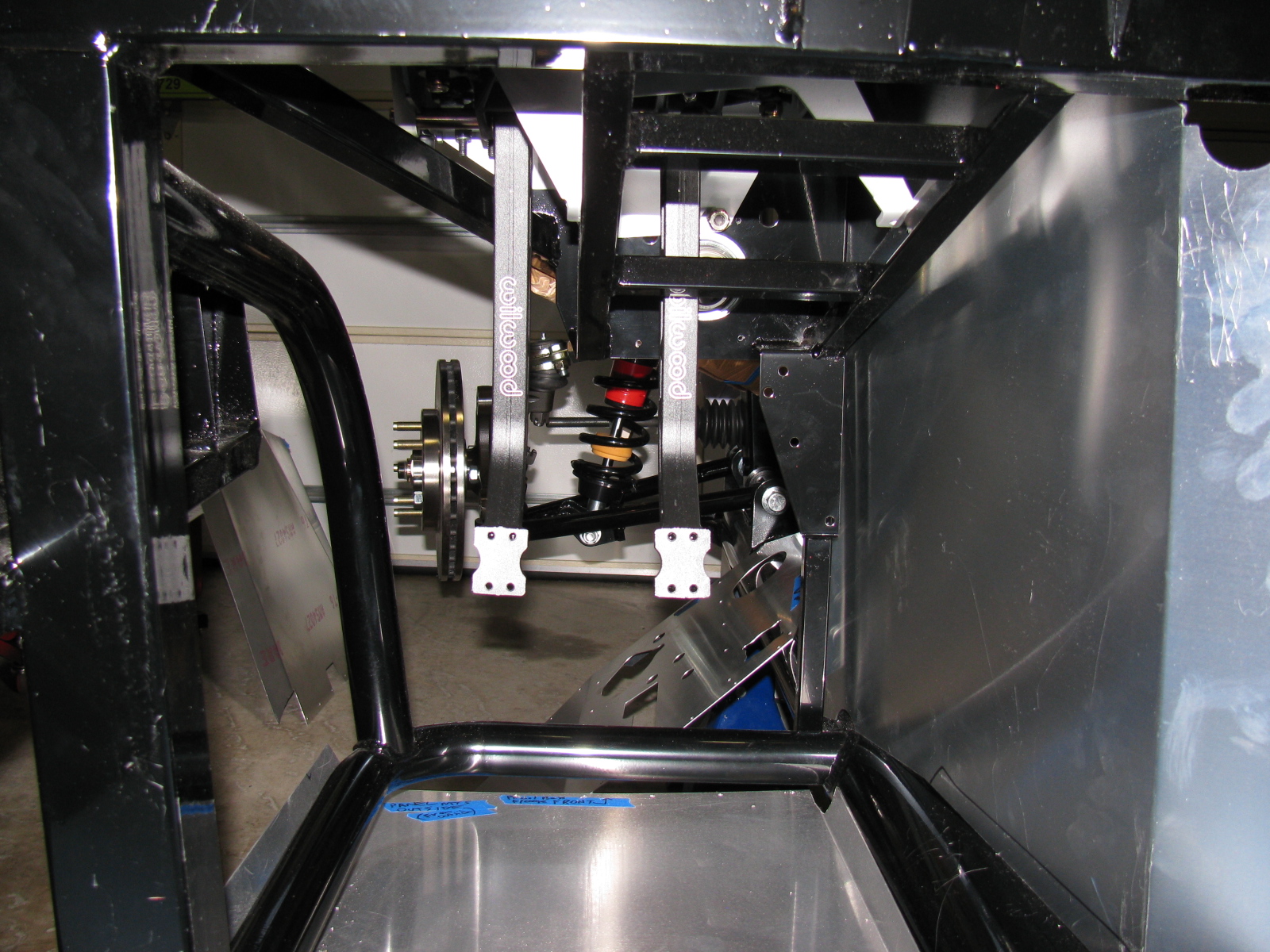
My go-to car builder friend Spider Larry once again came through for me. Using a Mapp gas torch and a piece of pipe, he separated the ball joint from the top mount for the passenger side suspension. Here are some pictures from the dis-assembly and re-assembly process on the Type 65 Coupe IFS, passenger side.


Here is the correct passenger side upper control arm and ball joint assembly:


The driver side looks like this:


So you MUST ignore the manual when it says to create a “left and a right unit with the ‘solid corner’ pointing to the front of the car.”
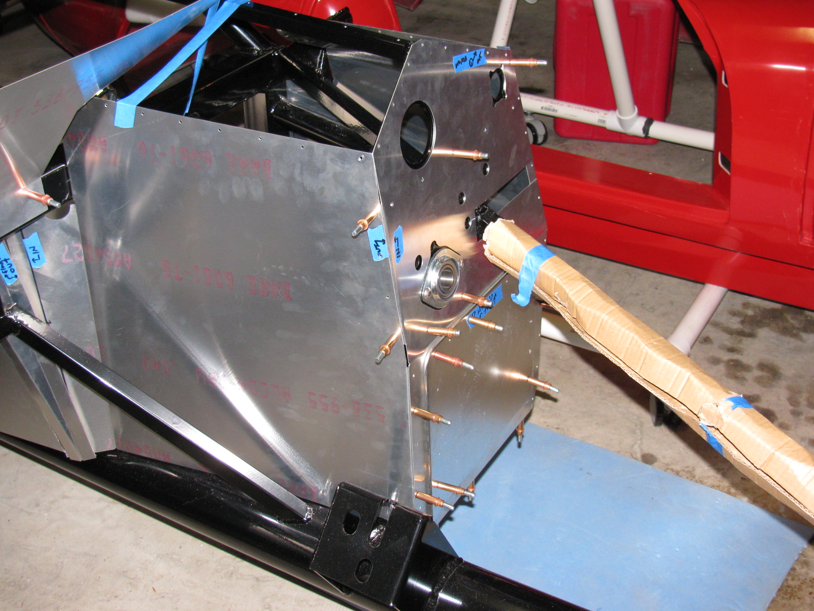
Footbox Heat Shields
I located, dry-fit, and drilled mounting holes for the driver and passenger footbox heatshields. The material is cookie sheet steel from the local grocery store. They have a nice rolled edge and will help deflect heat from the engine bay coming into the car interior. I am using riv-nuts and spacers to mount these sheets – er – heat shields to the footboxes.
I used BBQ paint for the shields, but may decide to powder coat the engine bay sheet metal parts, including the heat shields.
But I have to decide this quickly, since the engine is scheduled to be delivered within a few days!
Here’s the driver footbox with riv-nuts installed. All aluminum panels for the engine bay will be powder coated, the others will be painted.

Air Conditioning
Here is a picture of the air conditioner unit and where it will go. It fits behind the passenger side dashboard area, where a glovebox wold normally go. I need to allow space for the ducting and the windshield wiper mechanism, which mounts in the same area. A box to house the A/C unit will have to be fabricated.

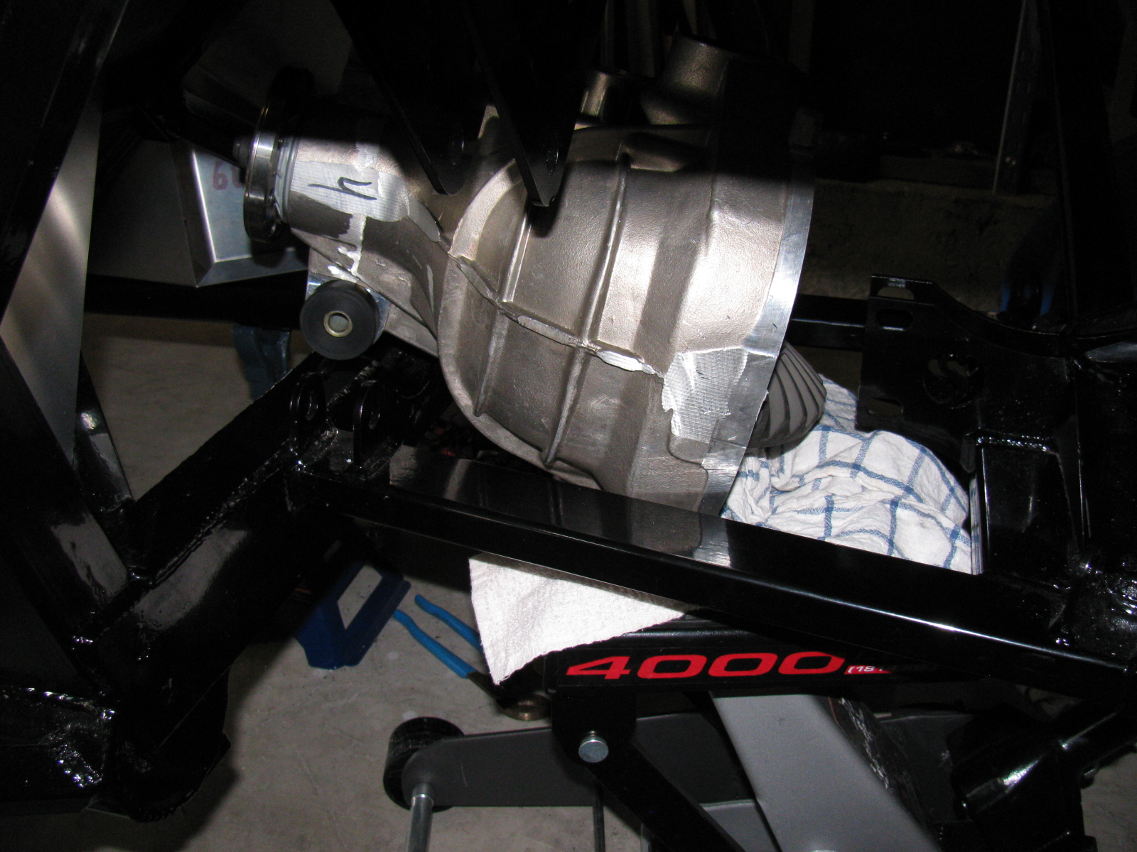
The IRS – Independent Rear Suspension
Note to builders: This procedure is quite difficult, even with a helper or two. It is highly recommended to keep small children away to protect them from hearing rated-R and -X words and phrases loudly coming from the underside of the chassis and to keep them safe from thrown objects.
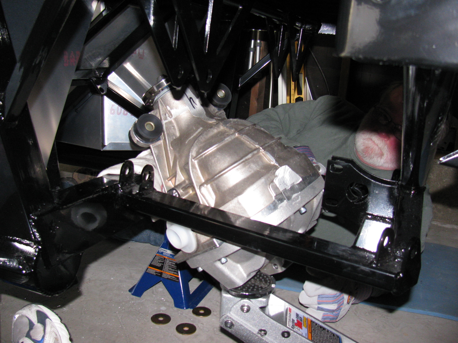
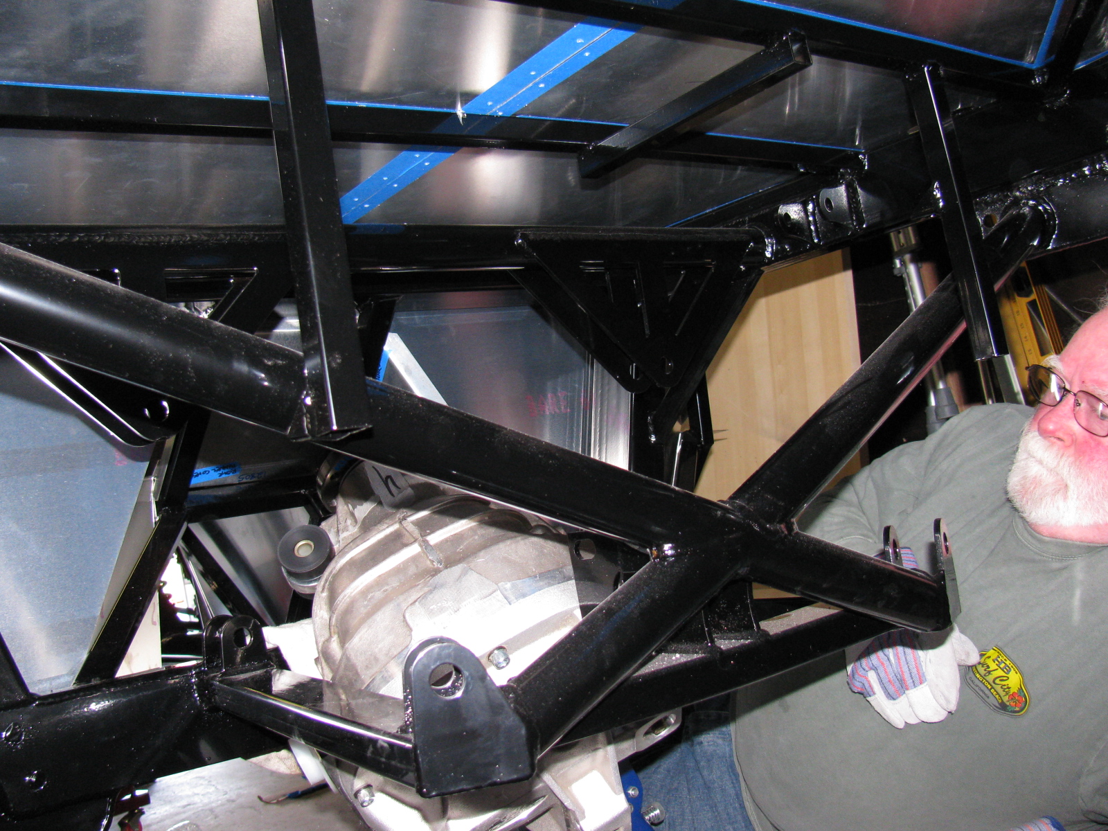
Since my ham radio friend Larry was going to stop by for a visit, I decided it would be a great time to get him to help me boost the rear differential (pumpkin) into the rear suspension cage. The Factory Five Racing assembly manual calls this unit the “IRS center section.”
There are many posts on how difficult this step is. The manual says, “It installs from the bottom with the driveshaft flange pointing straight up and the axle holes lined up front to back with the chassis.”
Err. So that means the giant 70 pound, lop-sided bowling ball like thing must be pushed up sideways, 90 degrees from the way it mounts onto the frame, and then must be twisted 90 degrees in the opposite direction to drop into place. This cannot be done safely with just one person. I found out that this is actually impossible to do with two people.
After several long hours and a phone call to Spider Larry, the pumpkin still refused to go into place.
I began to think about getting a grinder and removing any offending protrusions on the differential case and chassis to make this thing fit. My ham friend Larry had to leave, but a neighbor showed up, who also happened to be a car builder. I put Phil to work right away…
We tried a different route, maybe through the X-member at the rear of the chassis could work. So we used the jack to lift the differential high enough to check. We made a few measurements. No way.
We measured again, and noticed that no matter how you turn this pumpkin, it will not fit past the rear cover mounting plates.
We decided to remove the rear cover.
After unscrewing ten Allen bolts, and giving the rear cover a light tap with a rubber mallet, the cover popped off, very much like breaking an egg. To gain another inch of clearance, we removed the two plastic dust caps from the axle holes. Verifying that the diff does NOT have to come apart to mount the rear brakes, we put it back on the jack. Modifying the instructions, we lifted it with the driveshaft flange pointing up and the axle holes at a 45 degree (not 90 degree) angle, and pumped the jack. Now it went past the offending rear mounting plates, and into place.
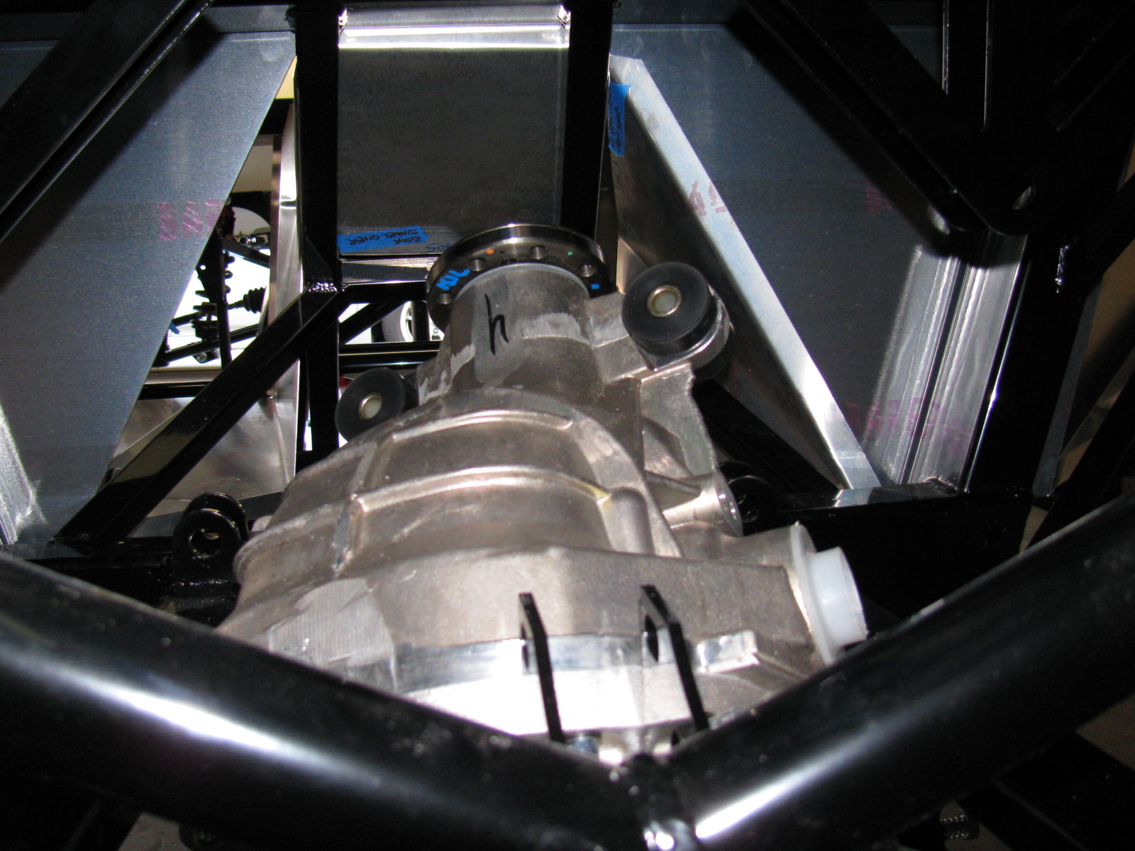
Of course, now the differential must be re-sealed, so we tried a dry run with the rear cover. Yes, this will work. I currently have the pumpkin suspended above the mounting location, held in place with the jack, a 2×4, and a nylon strap. I will finish mounting this beast at the next build session.
Here are lots of pictures of the wrong way to do this. A video of this procedure would be most helpful, but I am sure most builders will have enough in their hands to not have a camera operator getting in the way.


So – take my advice, save at least 6 hours and lots of non-child-approved words and thrown objects, and remove the differential rear cover before you install your IRS center section. . . .


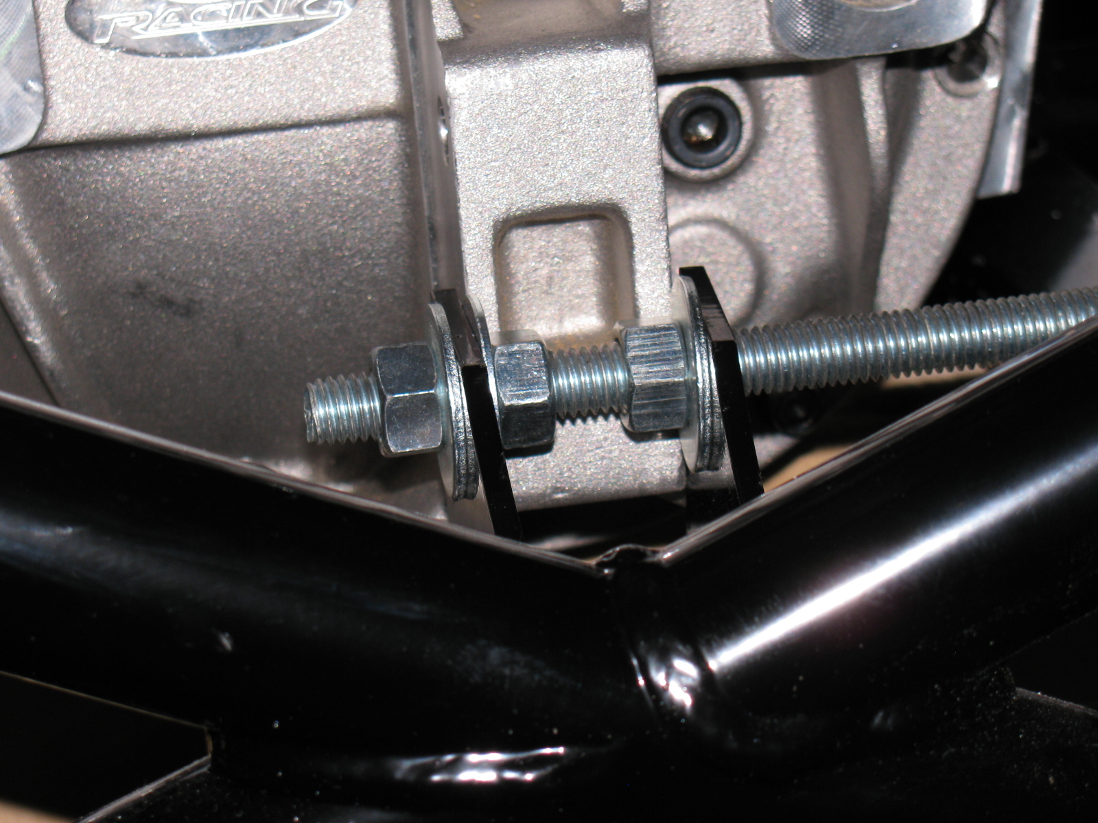
The rear mounting tabs (with the nice “5” logo laser-cut into them) are too close – use the threaded rod-expander trick to make it fit.
By the way – anyone else missing two nuts and bolts for the pumpkin mount? My parts list is correct, and yet I am still missing two fasteners for the standard width IRS differential.

I discovered I have the wrong adapter plates for the rear disc brakes, These are for the non-IRS version of the car. Jason at The Factory is sending the correct parts to me……

The front IFS is still not right, and the responses from the forums and the directions are confirmed by Jason at Factory Five Racing. Now the difficult task involves more un-building and hoping parts are not damaged. The ball joint on the passenger side needs to be removed and the upper A-arm top plate has to be flipped over. This is a direct result of an error in the Factory Five Racing Type 65 Coupe manual (revision 3E, July 2011) on pages 60 and 61 and 63 and 64.
The manual says to install the ball joint into the upper control arm to make “a left and a right.” I did this, and now must dis-assemble one of the ball joints. A new upper control arm is more than $200, so this is a costly error if I am not able to correct this.
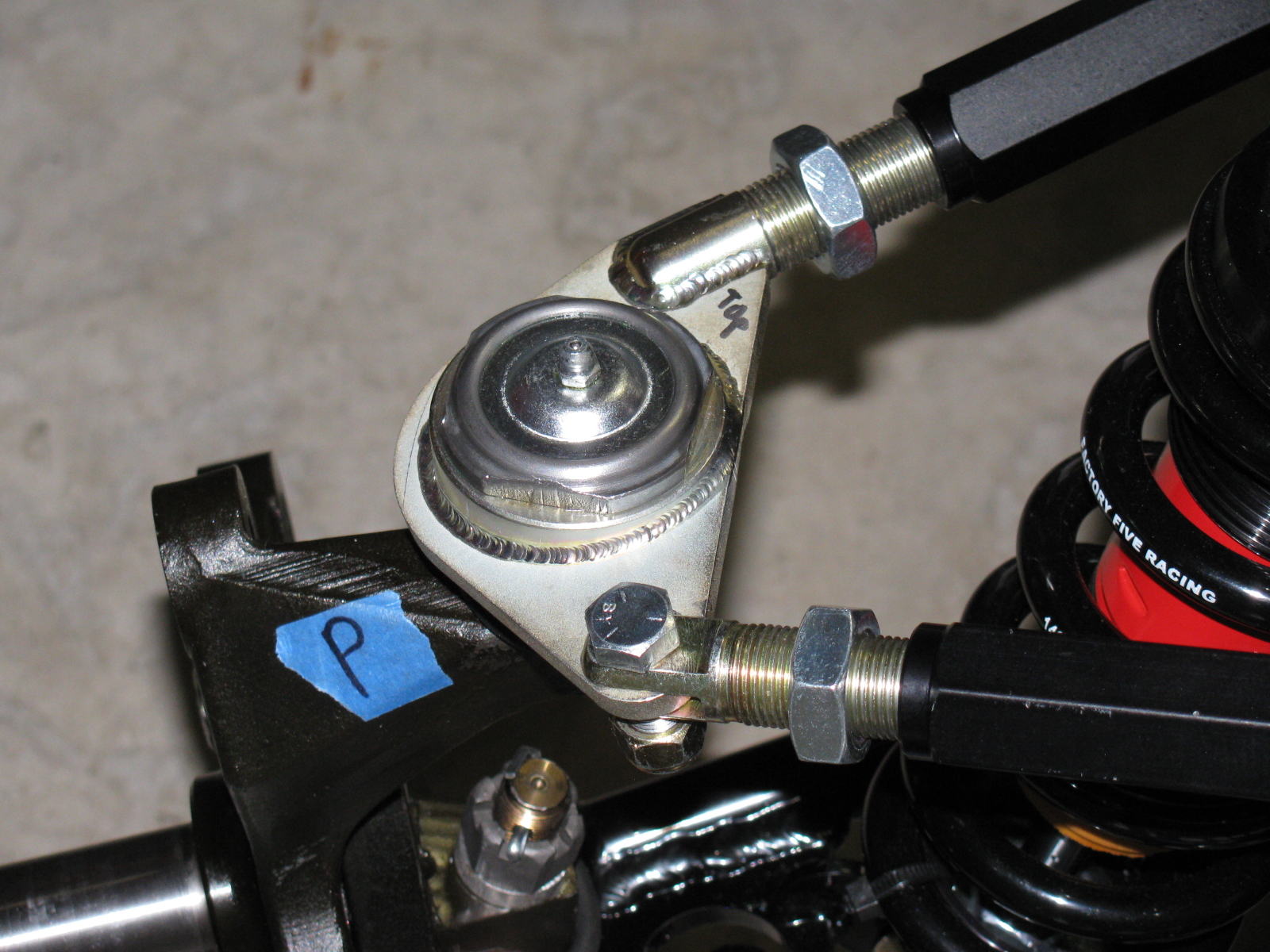
The correct orientation is shown on the driver’s side of the suspension. The passenger side is incorrect. This assembly is difficult to describe in words, so it is best shown with pictures.
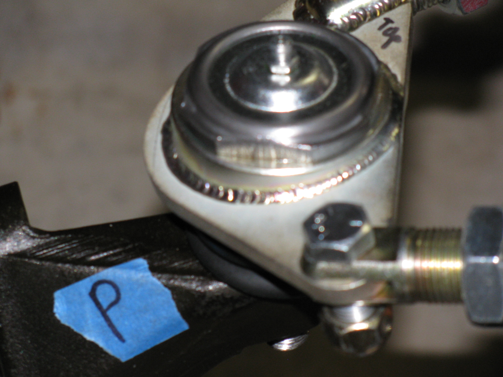
Here is the driver side showing the upper control arm and the ball joint mount on the plate – see the wedge-shaped, “thicker” end at the apex of the triangular plate? This is correct.


This is the passenger side upper control arm. See the thicker wedge-shape on the opposite side of the apex? This is incorrect (wrong).


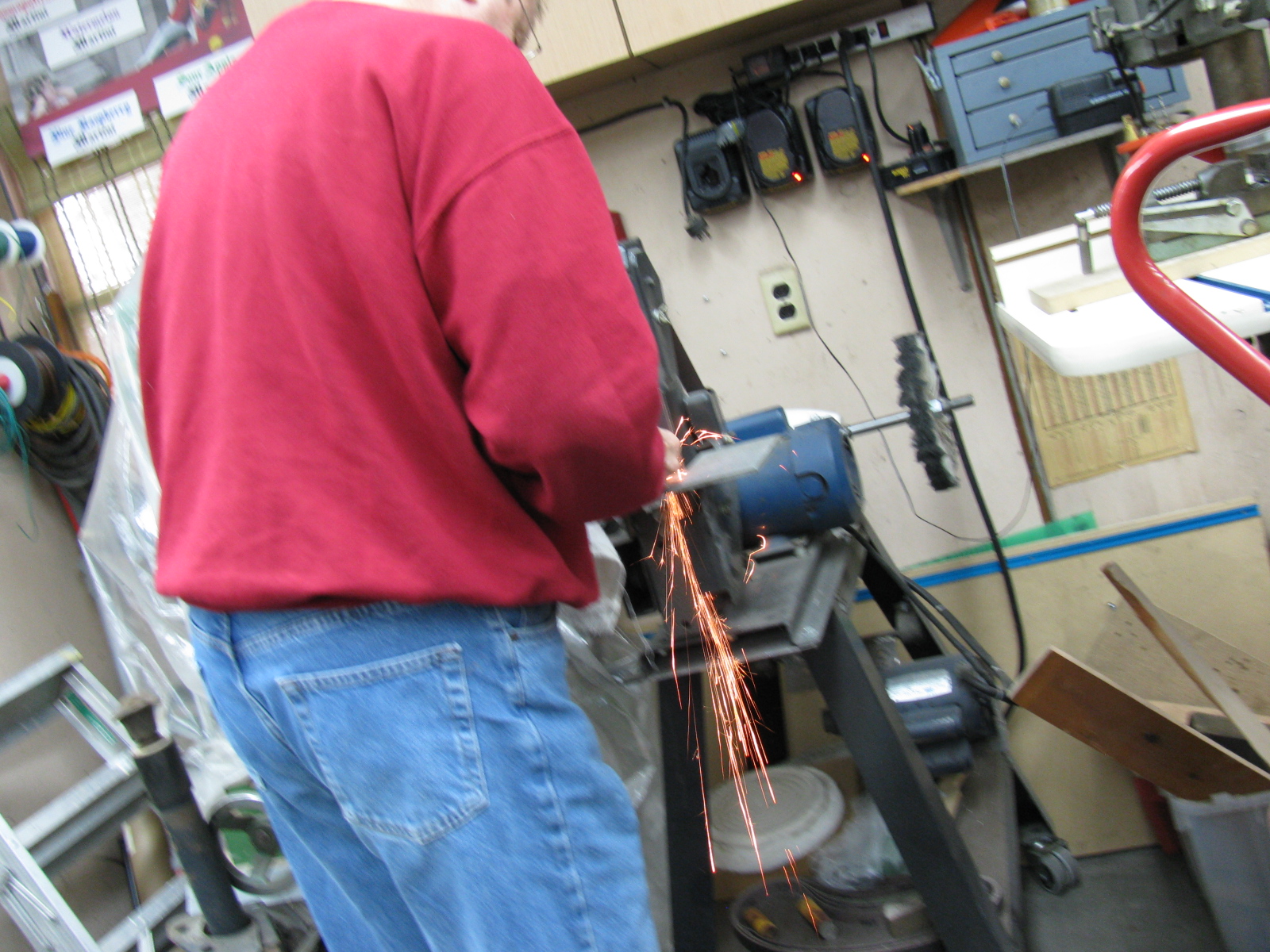
I dis-assembled most of the front suspension to get to this ball joint. However, the ball joint fits into the spindle via a tapered hole. . . meaning that some force must be applied to remove the ball joint stem from the spindle. I started by tapping – then pounding – with my plastic hammer, since I did not want to damage anything. No good. I changed to a scrap of oak and my ball-peen hammer and hit it hard for several minutes. Still no good. I got rid of the piece of wood and really slammed with the ball-peen hammer. Finally, the stem popped loose.
Of course, this created a mushroom on the ball joint stem, and it would not come out of the hole. I filed around the mushroom and finally separated the ball joint from the spindle. I should be able to file or grind the stem so the ball joint can be re-used.

Mushroom on the stem!
Removing the ball joint requires dis-assembly with 450 degrees F (since I used Permatex medium strength thread locker blue), a vise and a big wrench with lots of grip and torque.
I tried several times, but my vise just isn’t gripping the ball joint properly, it slips off. I need a bigger vise and a torch for this. My bench vise is too small.
Cutting the Dash
Since I could not remove the ball joint, I decided to move to another part of my project – cutting the dashboard in half. This is a popular modification that will increase access into the area between the dashboard and the firewall. This area will soon be stuffed with wiring and air conditioner ducting, so the dashboard had to be cut sooner or later.
I wondered how this was done, should I leave a “lip” on one of the sections so I can patch the panels together? Or do I just slice along the fold? What is the safest way to do this with my power jig saw?
It turned out to be easier than I thought. Here are some pictures of the cutting operation . . .

I used some duct tape and a wood scrap to hold the dashboard in place for the cut. My trusty Makita power jig saw did the trick.

I will use a piece of aluminum angle stock to mend the two sections together.
I may make a new dashboard front panel, especially since the original one has several things wrong. For example, I ordered the “modern gauges” option. There is no mention that the modern gauges are smaller than the vintage gauges. The dashboard comes with cut-outs for the larger gauges, and a triangular-shaped adapter plate for the smaller gauges. Also, the steering column hole is in the wrong place, as mentioned in a previous posting. If I knew this was going to happen, I would have ordered a plain, non-drilled dashboard – so if you are planning your order – consider asking for an un-cut, un-drilled dashboard and make custom cut-outs where you want them.
Cookie Sheet Heat Shields
A few weeks ago, I found these cookie sheets in the close-out bin at the grocery store. They have nicely rolled edges and they happen to be almost the right size for the footboxes.


The amazing part about these cookie sheets is the angle at one end – it exactly matches the angle at the back of the driver-side footbox. I will mount them with 8-32 machine screws, spacers and locking nuts. I will also add a layer of insulation (Cool-It mat) between the heat shield and the footbox panels.
I am no longer sure if I want to use the Rust-Oleum BBQ paint for my firewall and other panels. I did a paint test this weekend, and the paint is quite soft, and scratches easily.
The Battery Mounting Plate
After noticing how soft that BBQ paint is, I decided to do some more paint testing. This is the battery mounting plate. It is made of steel, and it is already starting to rust. So I decided I should paint this part and the other steel items soon.

I used Rustoleum Appliance Epoxy paint for this test. This is my standard paint for radio and electronics projects. The finish is very hard and glossy, the cured surface is washable and no primer is needed. However, it is not meant for heat, the maximum temperature is 200 degrees F.
I prep the surface by scuffing the surface with 80- or 150-grit sandpaper on a random orbit sander, followed by a dish soap and water wash. I apply the paint in three or four very light fog coats and the surface becomes slightly textured. I may go with this paint, if I can find a suitable color. The last time I looked at spray paints, this appliance finish comes in white, almond and black. Too bad it does not come in silver or gray.
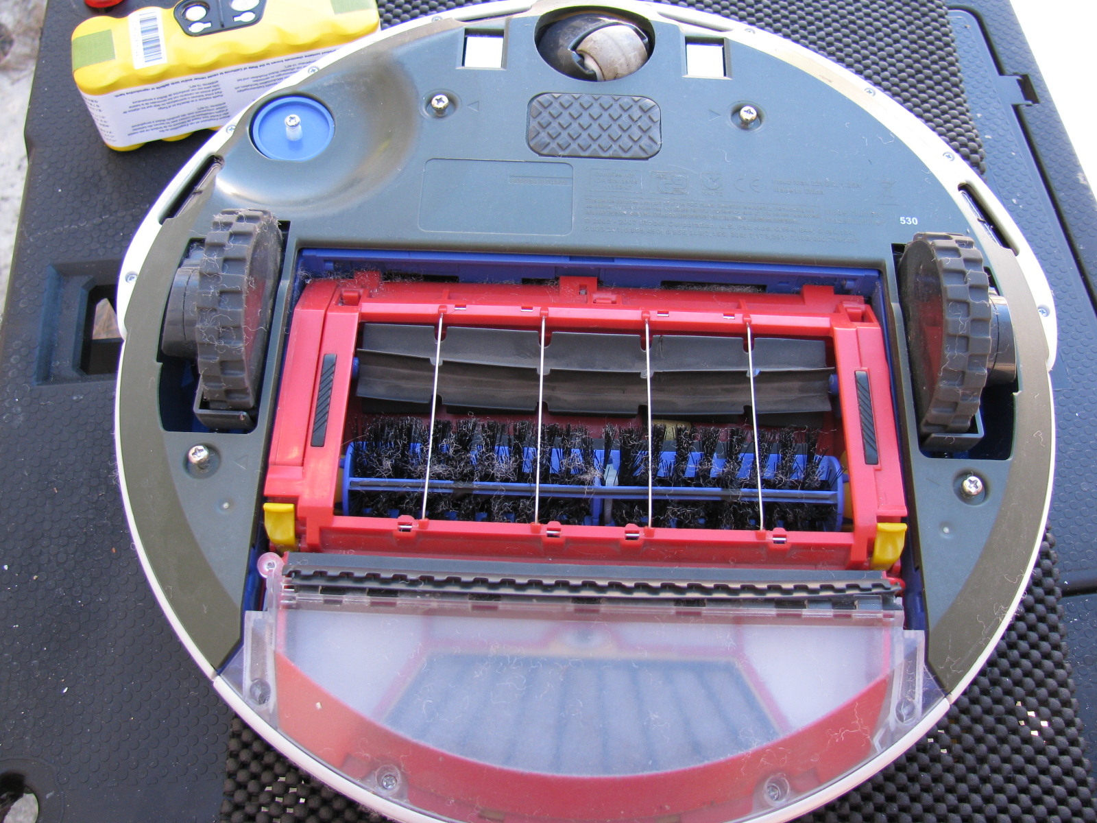
Roomba Battery-Ectomy – Vacuum Cleaner Battery Replacement
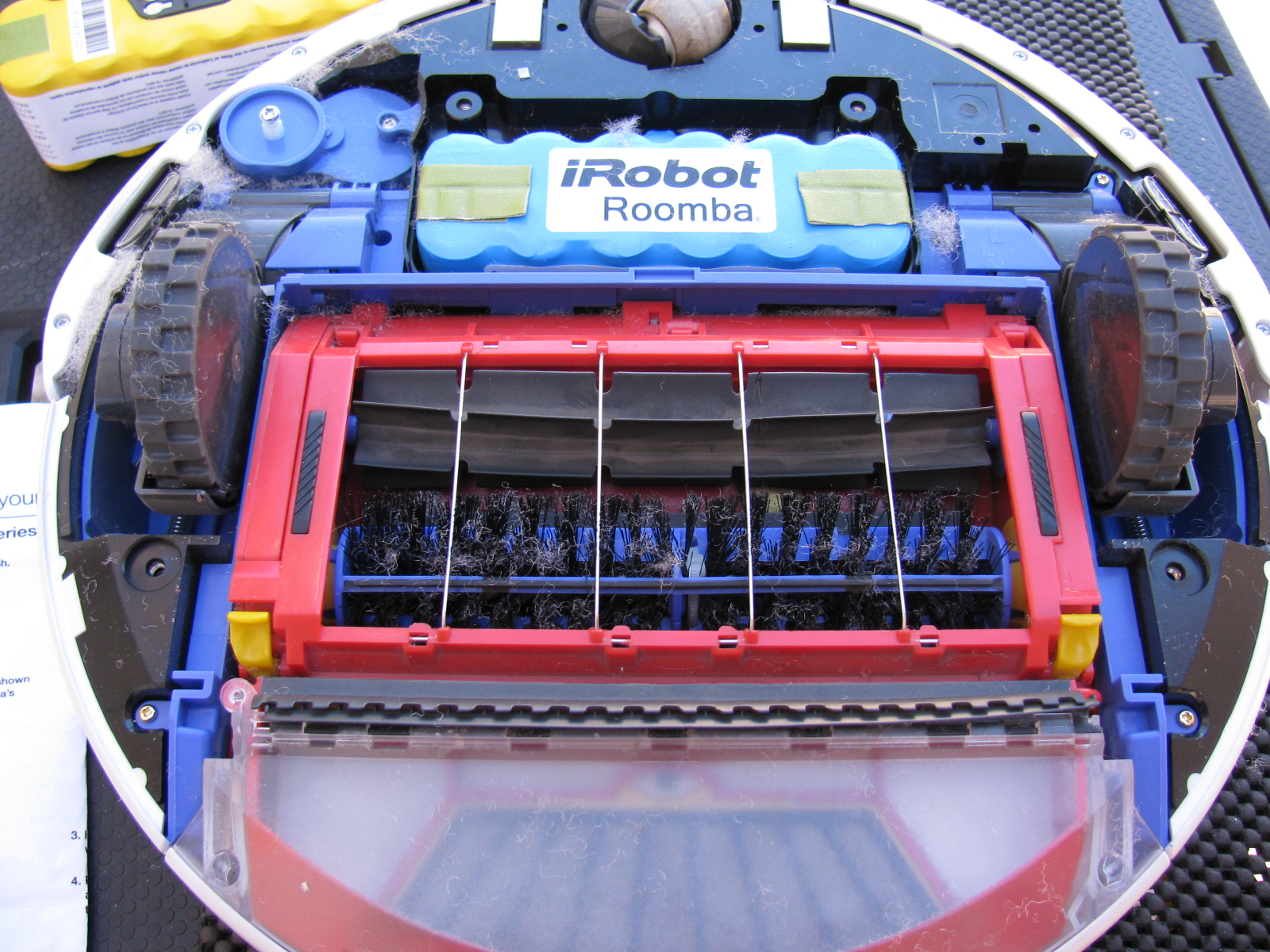
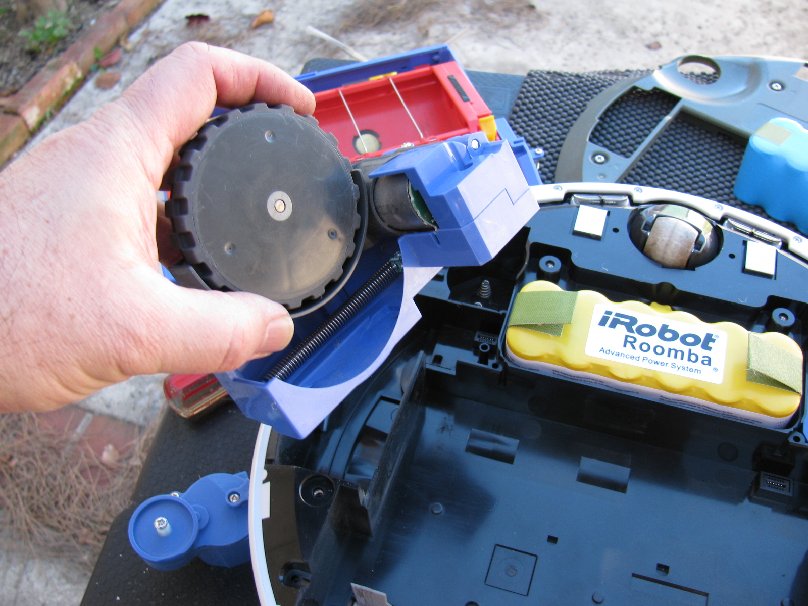
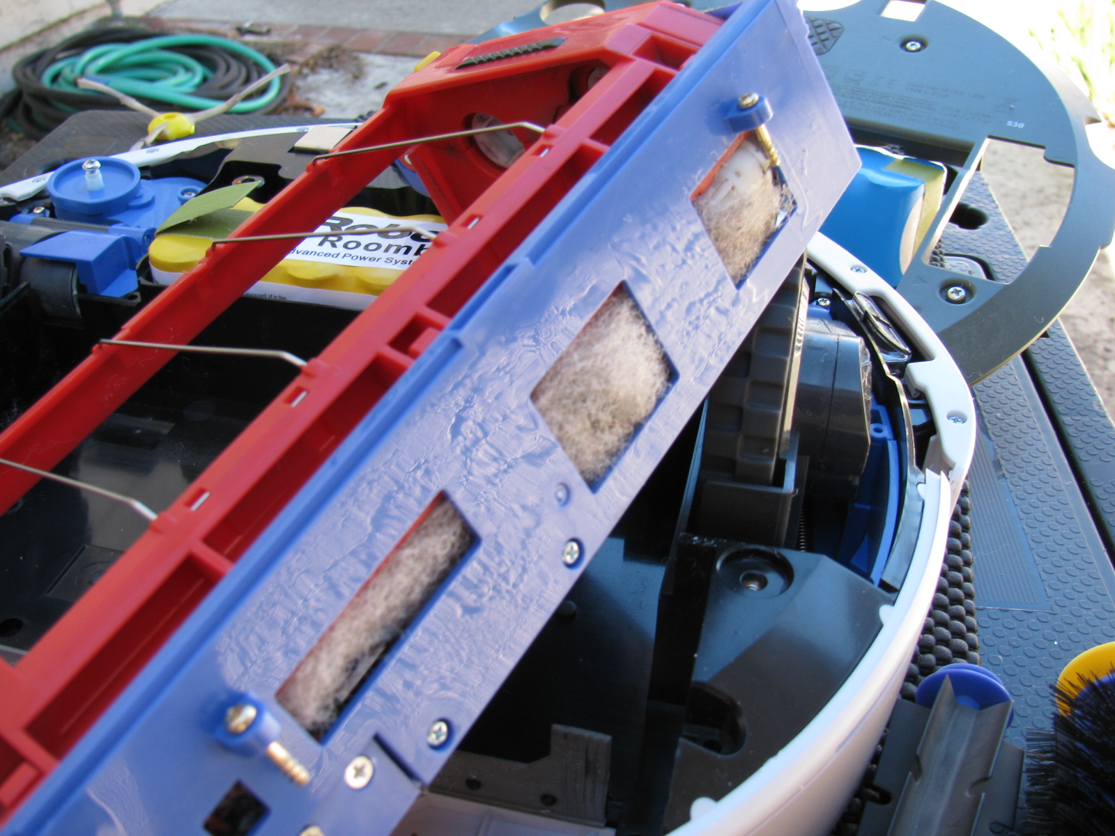
After almost three or four years, the battery pack in my Roomba 530 stopped taking a full charge. I re-newed the charge cycle several times, but the Roomba would run out of charge before completing a single room. So I performed a battery-ectomy on the Roomba. It needed a good cleaning inside the chassis anyway, so this was something I needed to do. You can see the debris inside the mechanisms that are impossible to clean unless you open the case. I used my shop vac to suck out the junk inside the various nooks and crannies inside the Roomba. The new battery has a larger capacity and should provide a longer running time. This will be good, since Roomba will help increase my time in the garage and other non-house cleaning activities. . . .
Here are some pictures. . .


I am working on several things on the car at the same time. Whenever I get stuck or run into a problem, I move to a different part of the car to build. At some point, things will meet up and progress in a more orderly fashion, but at this stage, nothing is complete.
This Factory Five Racing Coupe project is consuming my life. Even when I am sleeping, I have dreams about the car, the building process or driving the car.
But lately I have been having nightmares about the car….
Front Suspension Re-Do
I managed to install a part on the front suspension upside down and backwards. Of course, like a lot of automotive things, in order to get to that part, a lot of other parts must be removed first. Some parts required a tremendous amount of torque to install. These are parts that should never “fall off” like anything in the front suspension and wheel mounts.
So, one of the chores I had to do was to remove the front wheel bearings and hubs. I tried to remove the mechanical lock nut with my ratchet, but it would not budge. This is a good thing, since this one nut fastens the wheel to the car. Installing these parts required several very hard whacks with my plastic hammer and several Rated R and X words and phrases. I could not help but wonder how those parts would come off if I ever needed to repair or replace them.
Reading the forums made me lose a lot of sleep, since it seems that a lot of fellow builders have had trouble with this part, too. I bought an AC-operated impact wrench and some very large (36mm) impact sockets to remove the hub nuts. As a back-up, I also bought a large 1/2-inch drive breaker bar and a piece of pipe to increase the torque if needed.
I called my friend Larry over for some assistance.

Surprisingly, the breaker bar made the hub nut come right off. Even more surprising is the condition of the spindle where the wheel and bearing mounts – it still looks brand-new and without any distortions or scratches.

After purchasing the impact wrench, Larry sent me an e-mail advising me to not use an impact wrench on the front hubs, because this may damage the wheel bearings. I took this advice, and returned the impact wrench. Good thing I did not open the box. . .
Interior (Cockpit) Aluminum Panels
After the problem with building the IFS, I decided to “dry-fit” all parts from now on. This way I can verify everything is correct – or fix things that are wrong – before tightening the parts into place.
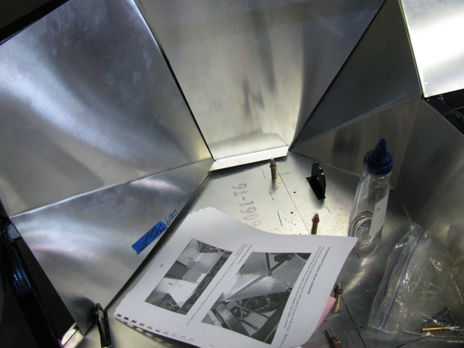
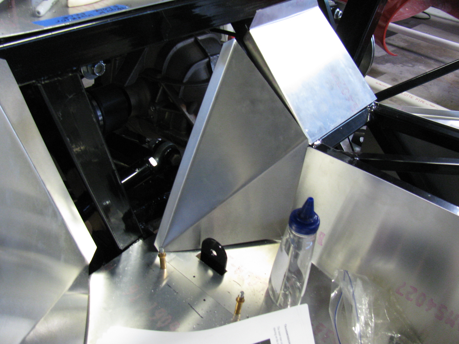
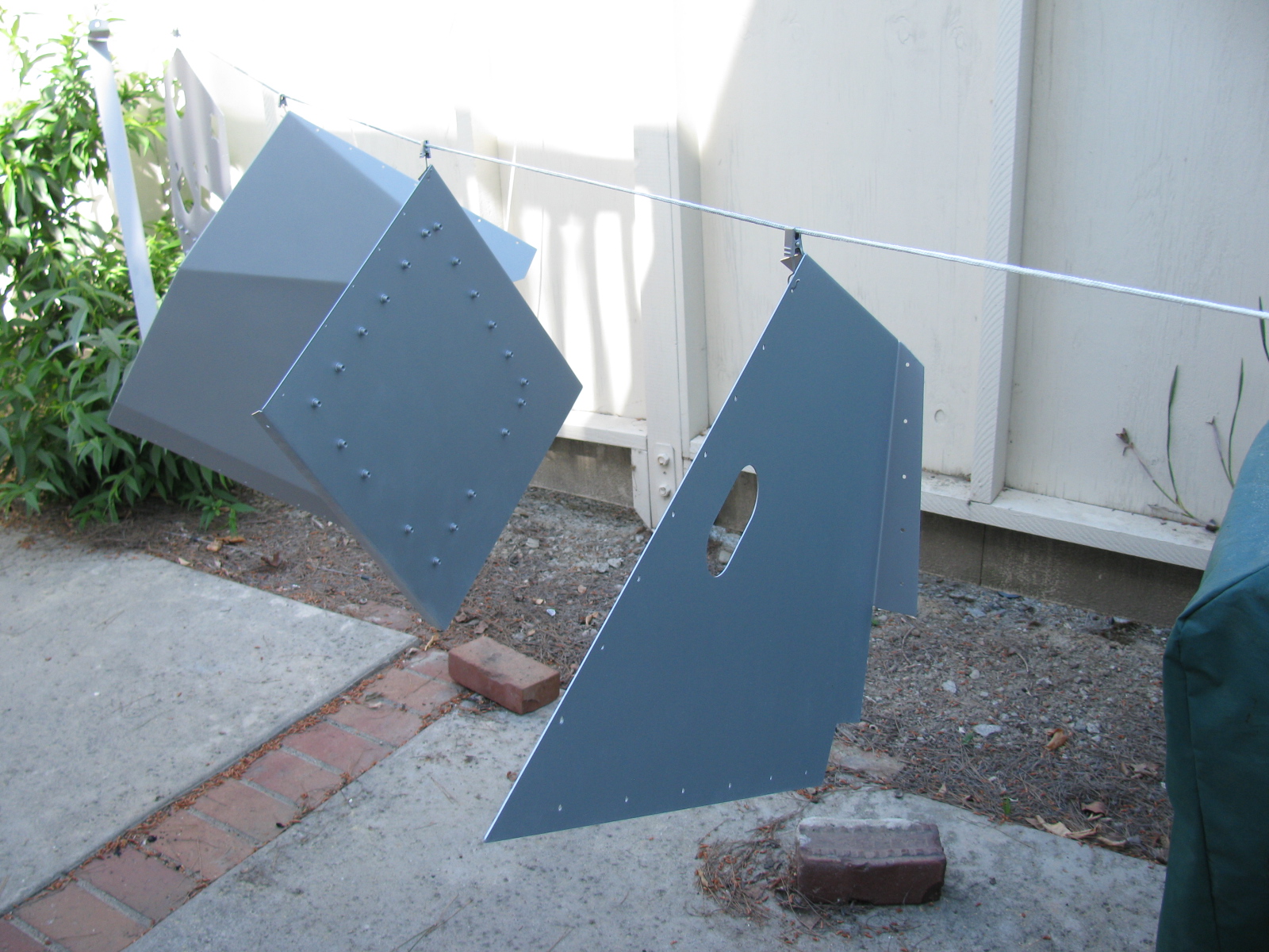
I decided to do some more work on the interior sheet aluminum. Compared to some of the other tasks, fitting the aluminum is easy. I made some diagonal cuts along the floor to make the parts fit easier, and to prevent scratching the nearby interior panels. By cutting the single large pieces into multiple smaller pieces, they will drop into place, rather than bend and scrape into place – preserving the painted surfaces.

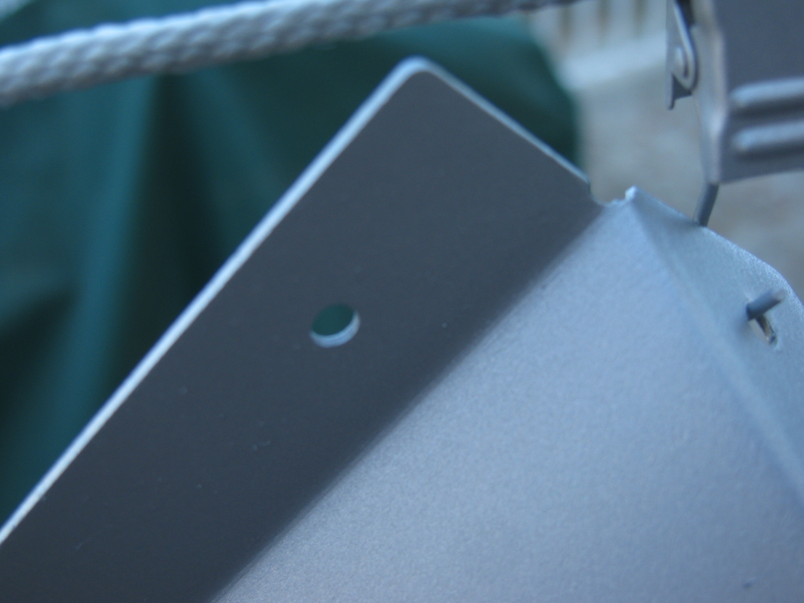
The seams and bend directions are hard to see in these pictures, the aluminum sheets do not provide enough contrast. I may use masking tape to show where the parts go and where the seams meet next time. As I said, this is the first attempt to fit the cockpit aluminum. Based on old Factory Five Racing forum posts, it looks like my aluminum panels have been improved somewhat. The only poorly fitting space is this big gap on the driver side, right at the corner of the transmission tunnel.

I may either trim the mounting tab behind one of the panels, or just install some sort of patch over the top. Overall, though, this Generation 2 Coupe seems to have better-fitting interior panels, so far.
Dashboard
Here is an example of something gone wrong —

Notice the odd-shaped hole for the steering column? The mounting location for the steering shaft is not straight and parallel along the ladder structure in the driver side footbox and clutch quadrant. As I examined all the parts in this area, I believe the factory did this because of an interference issue with the brake pedal. If the steering column shaft were to run parallel to the ladder structure, it would block the brake pedal actuator. Moving the mount – but not compensating for this on the dashboard panel – makes this problem look worse than it may be.
I used a nibbling tool, a round file and a sanding drum to enlarge the hole for the steering shaft.


A popular modification to the dashboard is to cut along the bend, making the one long piece dashboard into two long pieces. This enables access to the inside of the dash from the top as well as the front, and will make installing and maintaining dash components such as gauges, air conditioner and plumbing much easier. I will make this cut at the next build session.
I just have to figure out a way to disguise the big and ugly hole in the dashboard. . .
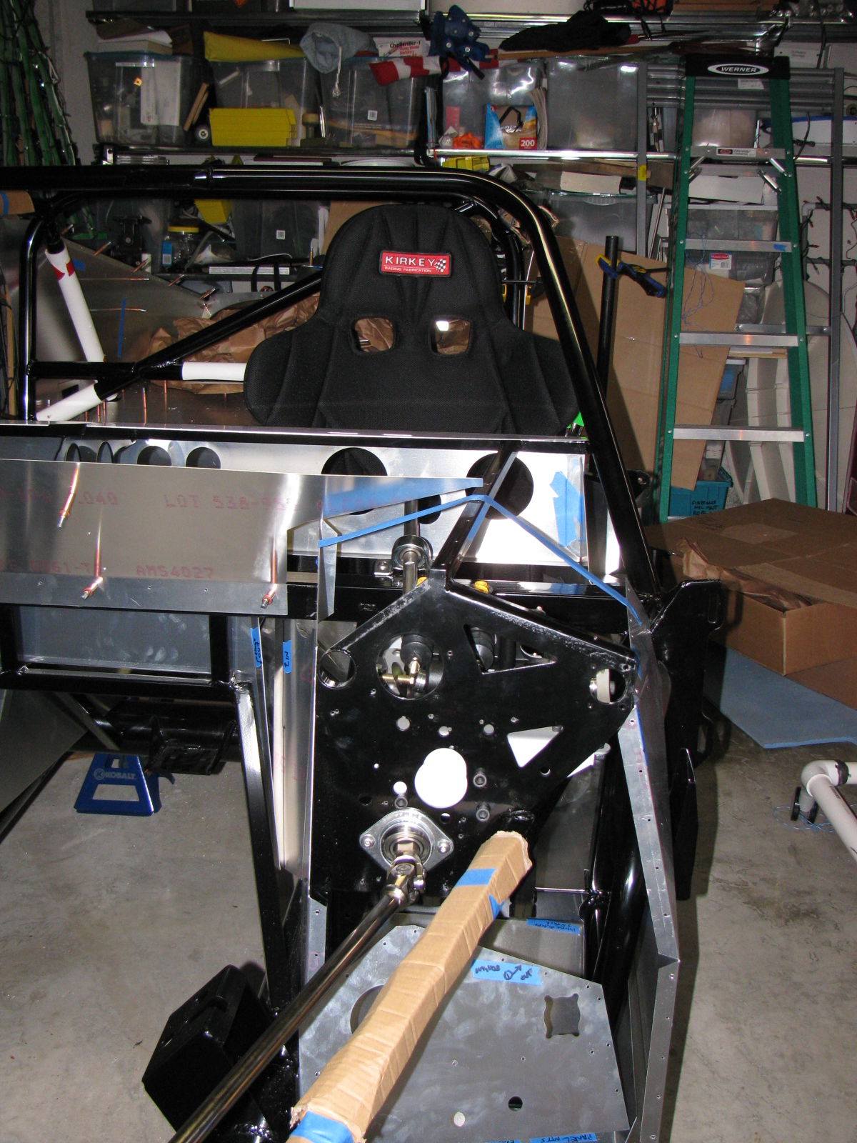
The Racing Seats
I placed the Kirkey high-back racing seats to see how it fits, and although the steering wheel is a bit toward the passenger side, I think it will be all right.


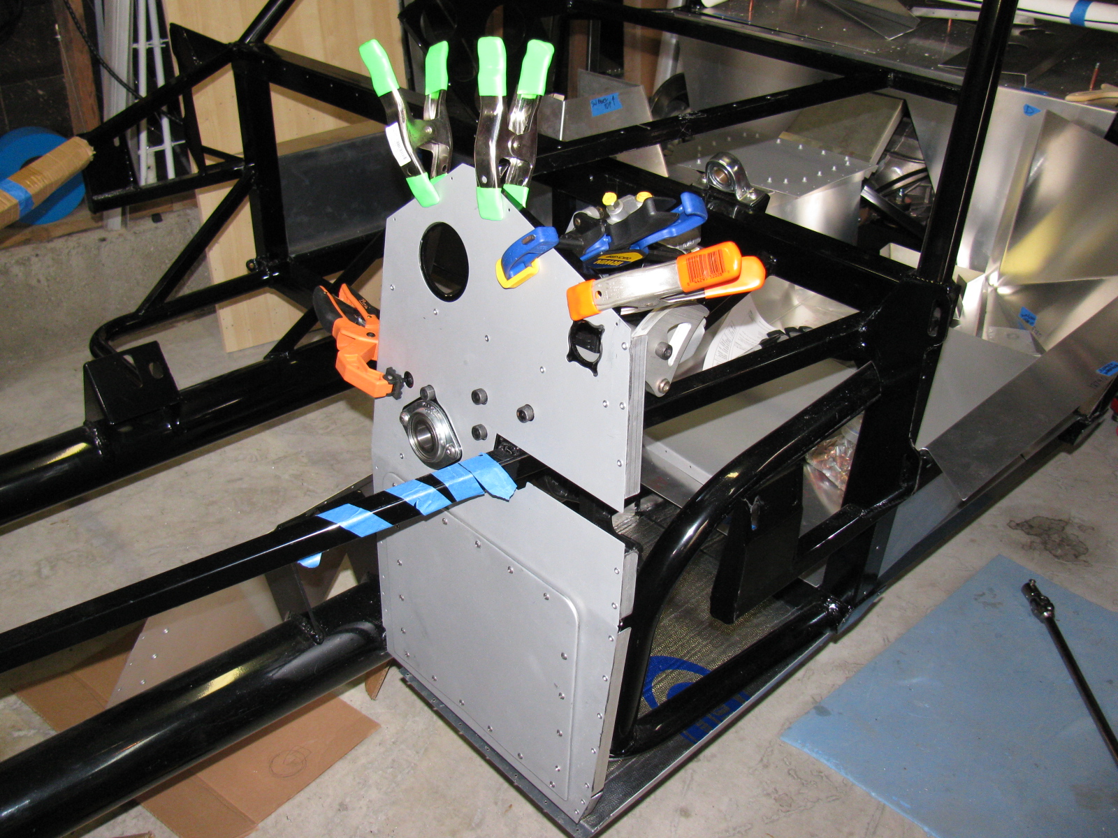
Clutch Quadrant and Pedal Box
Many Coupe builders owe a lot to a guy named Chris, who has documented his Type 65 Coupe build experience with lots of pictures. (I added a link to his flickr photostream in the Automotive Links section.) The Factory Five Racing assembly manual left an entire section out for us Complete Kit builders. There are no instructions for the Wilwood pedal box and clutch quadrant assembly. Thanks Chris for sharing your images!
Anyway – here are some pictures of my Wilwood pedal box and clutch quadrant. I do not have too many fitment issues here, except for the mounting points to the 3/4-inch tubes – I will have to wedge the mounts at the firewall in order to securely mount the pedal box to the ladder structure. I painted my footbox mounting plate with silver Rust-Oleum BBQ paint. I wanted to do a test to see how the color came out and how durable the finish is. I like the color, it is much better than the raw steel and hopefully will prevent any rust from forming inside the car.


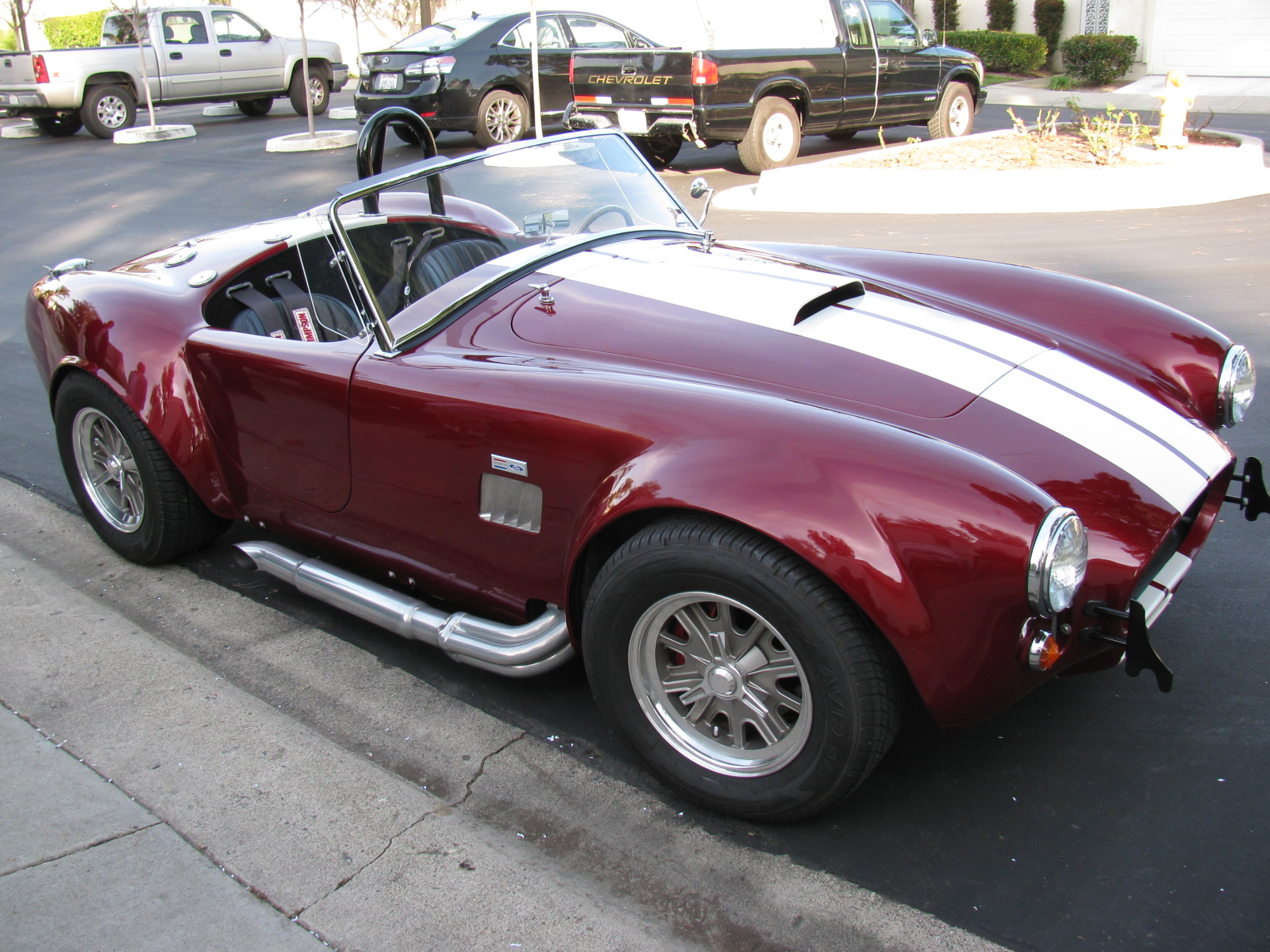
A Roadster Driver Visits
Rick, a neighbor and Roadster owner, stopped by for a visit. Here are some pictures of his very nice car. Rick did the paint job by himself in his garage – I am very impressed with the way the finish came out – take a look!


It’s been cold in the garage lately (50s-60s), but I wanted to get some more work done on the Coupe. My 302 is scheduled to arrive this month, but I have a lot of work to do before I can install the engine and transmission. This is one of those rare times when I can tell a supplier to take their time.
Back to this weekend’s update: What’s cookin’. When I lived in a small townhouse, I used to make a lot of meals in a Crock Pot, and noticed a few things: First, it was very handy to fill the thing up with various meats and vegetables, turn it on, go away for a few hours and dinner would be ready. Second, the smell was always wonderful. And third, it actually made the house a little warmer.
I decided this third effect of Crock Pot cooking deserved a try in my garage – and it worked. In the morning, I filled the Pot with my universal minestrone recipe and added some leftover spare ribs from the freezer. I call it “Spare Rib Minestrone.” The recipe appears at the end of this entry. It is roughly based on a minestrone recipe from Fat Free, Flavor Full: Dr. Gabe Mirkin’s Guide to Losing Weight & Living Longer. And it is pretty tasty. It made the garage a few degrees warmer, too. Here’s a picture. . .

Cooking in the garage – a tasty alternative garage heating method!
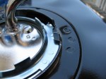
Halibrand-Style Wheels Arrived
The Factory Five Racing Halibrand-style wheels are BIG and beautiful. Wheels are 17 x 9 in front and 17 x 10.5 in the rear, and feature a spin-off hub. I am still not completely sure what tires will go on these rims, my preliminary choice is a set of Goodrich Sport-Comp 2 or something like that. This may change as I get a little farther along on my build.


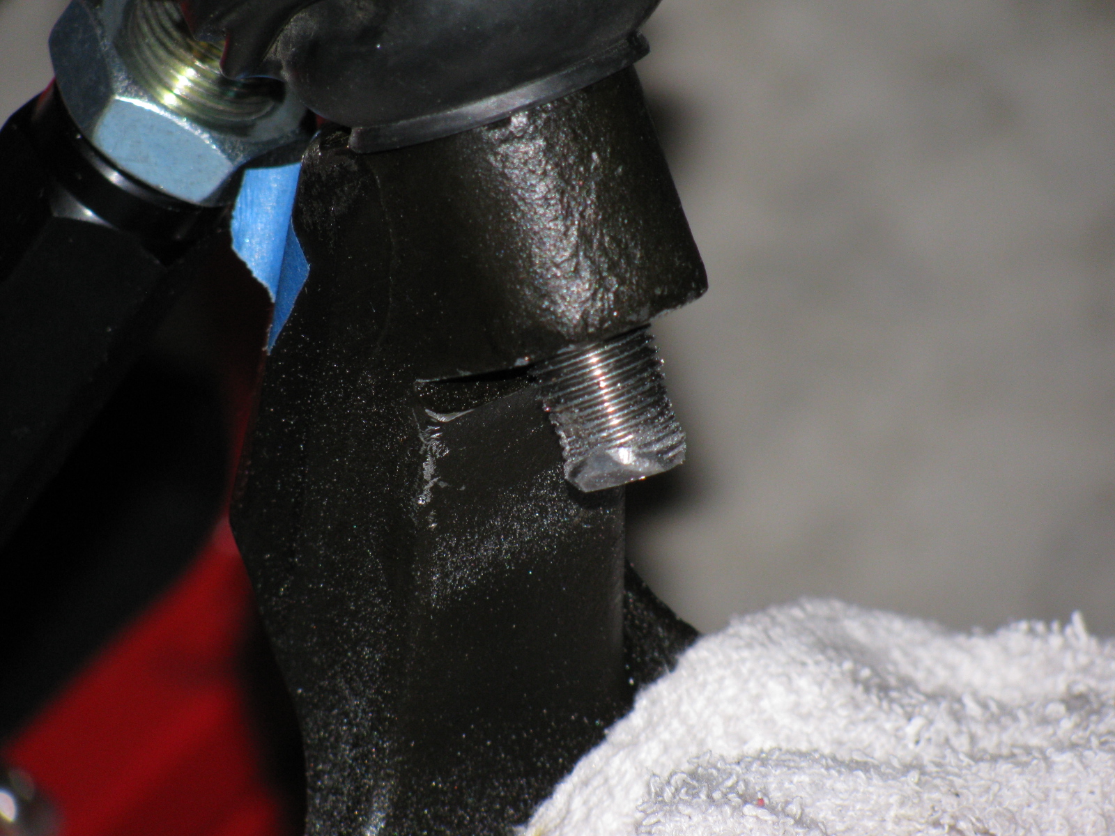
The Steering Rack
I decided to see if I could finish the front end this weekend, especially since a lot of the back-ordered items arrived – I finally have a complete set of parts for my complete kit!
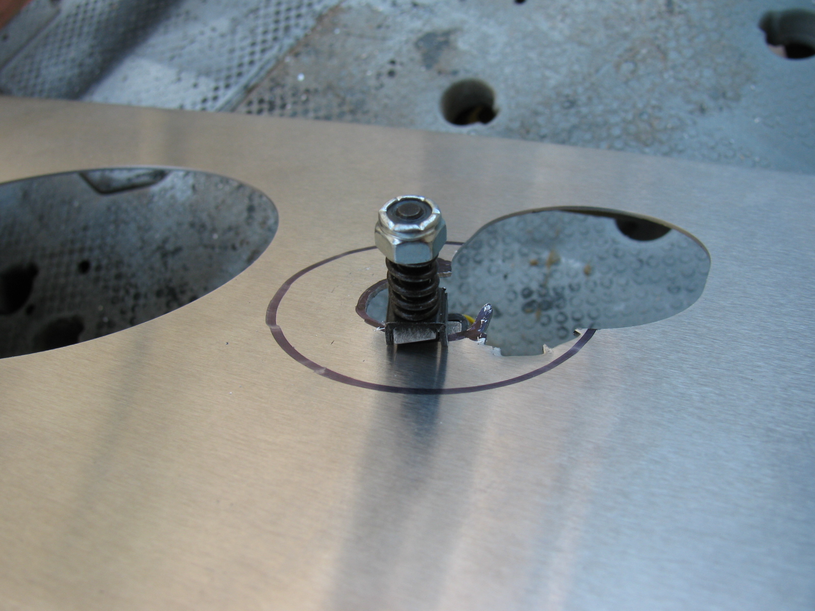
The steering rack is a non-powered unit made for the Mustang. Like many others, the mounting ears were too close together and I had to spread them out by a little over a quarter of an inch. I tried to use my pipe wrench trick, but the tabs are a little small and I wasn’t able to exert enough torque to move them. Doing some research on the Factory Five forums, I kept reading about people using a nut and bolt to spread mounting tabs wider. I finally found a post that included a picture of this, for future reference, it is located here, and I am posting photos and captions on my site as well so it may be easier to find. It’s a pretty neat trick, although no one says anything about the mounting tabs springing or bending back into their original position – you have to “over-bend” the tabs in order to make the part fit.
Here is my version of the mounting tab spreader tool using threaded rod, washers and nuts – I used 1/2-inch all-thread, since the 3/8-inch rod seemed a bit flimsy:

This really didn’t work too well, the tool needs another nut to hold it securely.

Like this

In the photo above, the open end wrench is being used to spread the mounting tabs outward. If the mounting tabs need to be smaller/tighter, move the washer and nut to the outside of the tab, and tighten the nut – squeezing the tabs closer together.
For the steering rack, I ran into another problem – that turned out to be a non-problem. As you can see here, after spreading the tabs out, the rack fits between the ears – but the holes on the passenger-side need to be moved about an eighth or a quarter of an inch to the left. After thinking about how long this will take using a rattail file, I took a break and thought about the steering rack. The driver’s side mounting tabs had a slot on one side – how come I am not able to move the rack over towards the driver side of the chassis?
The answer is, of course, yes, the slot is just enough to make the rack fit nicely. I used a punch and a mallet to move the rack into position. Success!

Compare the hole on the left (I used silver marker to show where to enlarge the hole) and the slot on the right. No reaming needed – I used a punch and a mallet to move the steering rack into place.
So now the tie rod ends have to be connected to the steering arms. But here is another problem – the driver side tie rod is too long – can I just get a hacksaw and cut off about an inch, as shown by the blue tape?

The driver side steering rack tie rod seems too long – but wait – something is amiss. ..
I decided to stop the steering rack installation at this point and get some answers before cutting the tie rod – because, as Norm Abram always said, “Measure twice, cut once.”
I came across the Summit Racing – Factory Five Racing Roadster build today – and there is a nice picture of the steering rack-tie rod connection posted here – this is for a Roadster, but I think the Coupe shares the same configuration. I have to give F5R a call to verify something – in the Roadster build, the steering tie rod to steering arms are upside down compared to my “dry fit” – Do the Coupe tie rods mount the same way? Also, the Summit Racing car has two lock nuts for each tie rod – my kit came with one lock nut for each side. The manual does not show the ends of the steering rack – poor photo-cropping.
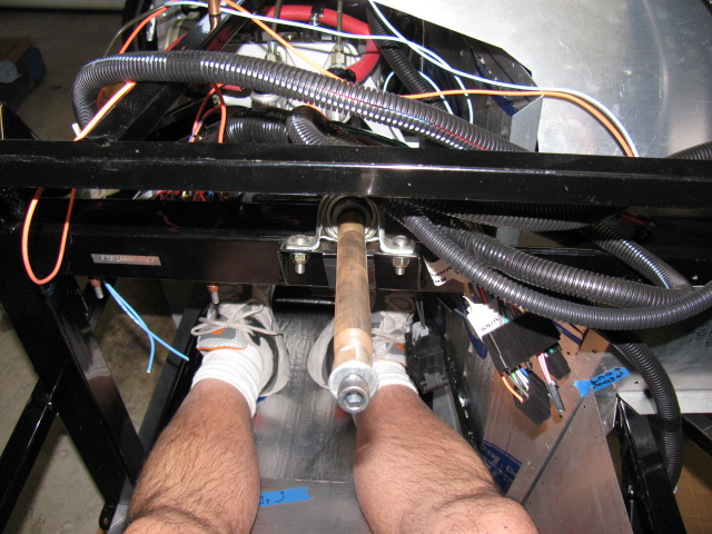
Getting the Shaft
I did some test-fitting of the steering shaft – after some head-scratching moments, I figured out that I needed to remove the adapter that came with the lower end of the steering shaft, and replace it with another one, from another box of stuff. The length is just right, I have seen some early posts about the steering shaft being too long.
But I ran into another problem – the shaft does not come through the dashboard in the correct position. It is not as bad as some others I have seen, but still is quite a ways off. I am not sure if I can just cut the dashboard hole bigger to allow the shaft to come through, and patch the spaces or – what. More fiddling is needed.
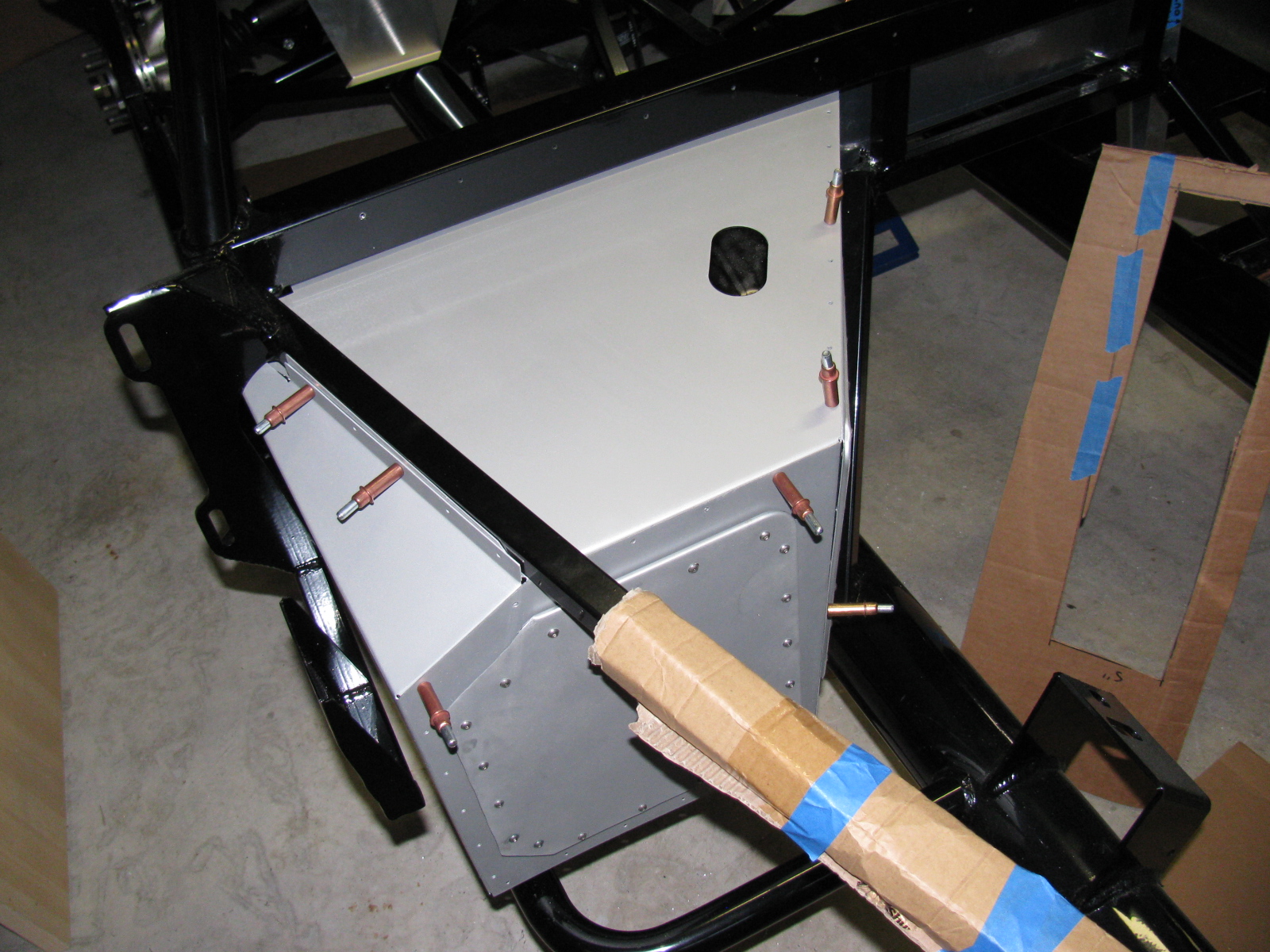
Floor and Footbox Fitting – Passenger Side
I decided to do some more sheet aluminum work – this time, fitting the passenger side floor and footbox. Using the same technique as the trunk floor, I cut the passenger floor into three pieces. After the cutting, I noticed that I could have done this with only one cut, but the three pieces will be OK. I kept the left side un-cut, since it may be seen when the car is done. (I am not sure if I will apply paint or put carpet on the transmission tunnel area yet.)
At this point, everything is being held in place with Cleco pins. I want to test-fit, trim, drill and de-burr all the aluminum panels first, then apply paint – or powder coat them.
So although I think I did a lot of work on the Coupe this weekend, a lot of it does not seem to show. It still does not look like a car yet.

Cutting the passenger side floor.

Passenger side footbox – another jigsaw puzzle!
Something is Making Me Go – “Hmmmmmmm”
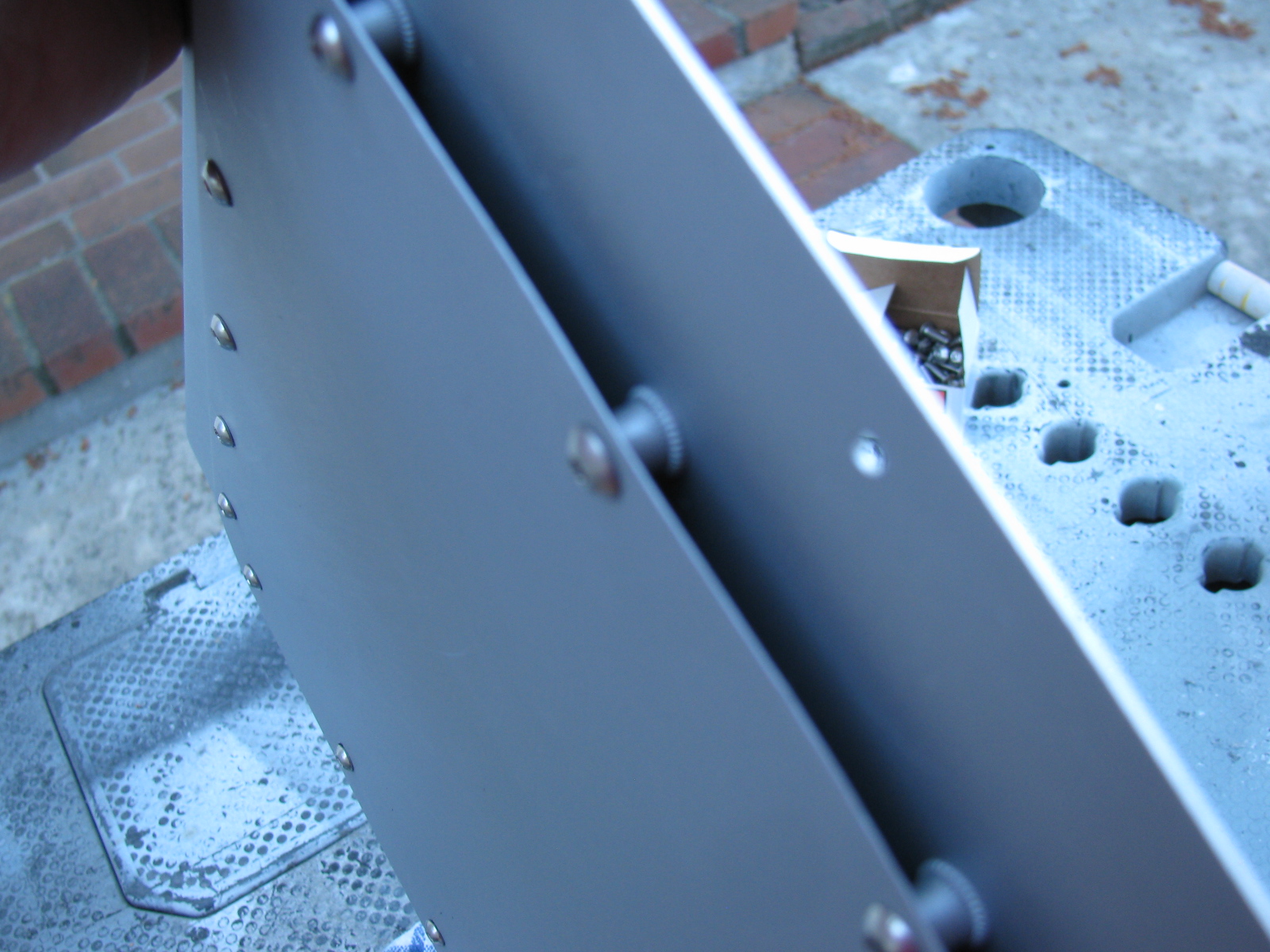
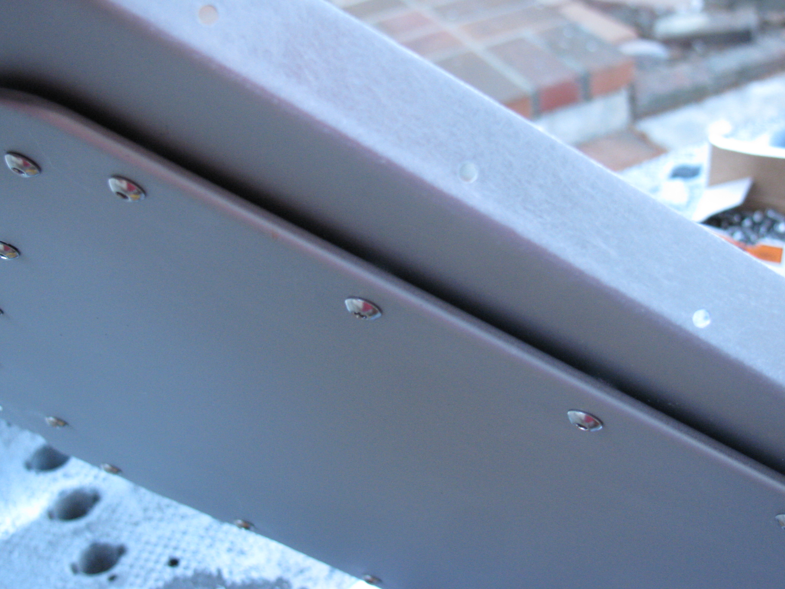
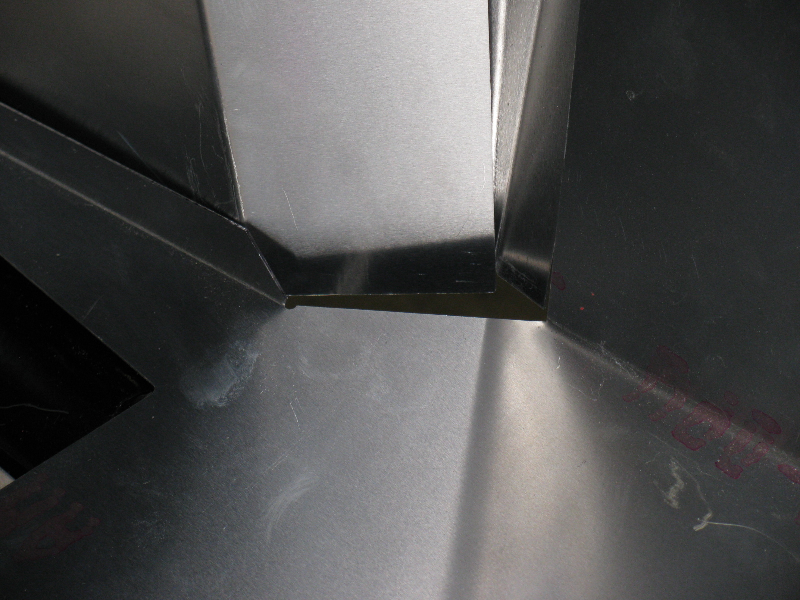
I noticed and wonder why the passenger-side side body mount area sheet aluminum is different from the driver-side side body mount area aluminum – take a look:

Driver side – side body mount near the footbox. . .

Passenger side – side body mount area, near the footbox – see the difference?
Here’s another look:

Driver’s side

Passenger’s side. . .
This is making me go, Hmmm. Or more like Arrrrrg.
Season’s Greetings
Somewhere during the weekend, I installed my Christmas lights. I decided to cut back this year, because of all the work I am doing on the car. My “Ho Controller” and box of new lights and other parts I bought last year will have to wait until next year. In the meantime, here is a shot of my display. One of my Universal Rules for events is: “Everything you setup must be taken down and put away.” So many people spend hours and days – or even longer – putting up such decorations. My setup: less than 10 minutes to deploy, and even faster to take down!

Before I forget – here is the Spare Rib Minestrone recipe:
Spare Rib Minestrone
Yield: 6 servings
1 Large onion, chopped
5 cloves garlic, smashed
2 celery stalks, diced
2 cups of chicken stock
1 28 oz can of crushed tomatoes
1 tsp oregano
1 tsp basil
1 can pinto beans
1tsp red pepper flakes
6 small red potatoes, diced
1 large zucchini squash
Some leftover spare ribs, with BBQ sauce
Put everything into the Crock Pot, with the leftover ribs on top, surrounded by the vegetables. Put the Pot on High for about 6 hours or until the vegetables are tender. Based on the Primo Minestrone recipe by Dr. Gabe Mirkin, MD in Fat Free, Flavor Full