Archive for the ‘master cylinder’ Tag
Not much to report on the Type 65 Coupe Project. I have been doing a lot of other things over the last few weeks. The heat has been making me lazy.
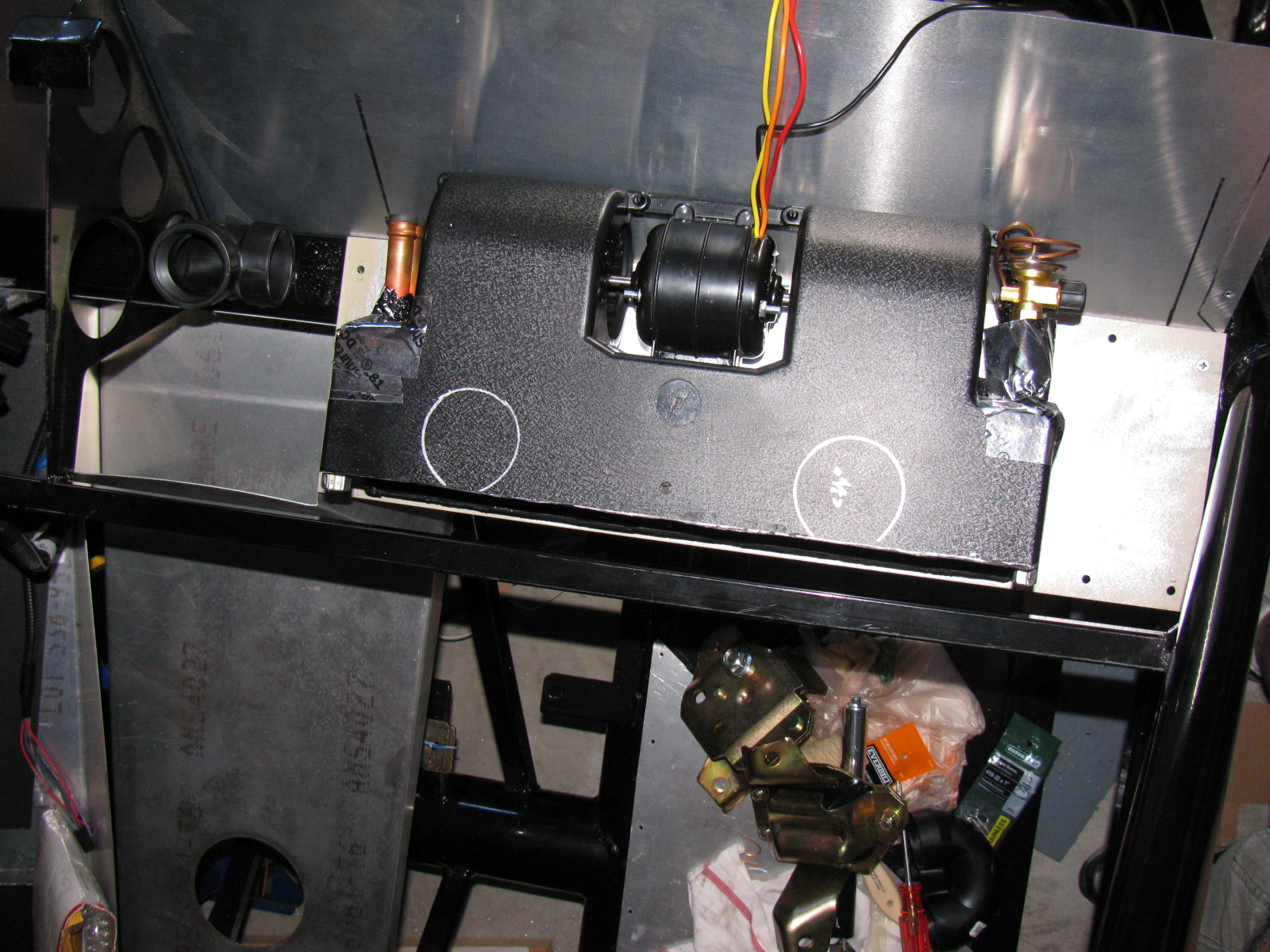
I decided to do some work on the A/C unit for the Coupe. I cut and chopped the housing cover for several hours, and then decided it might be easier to just make a whole new cover using fiberglass and resin. . . . I did some research on composites, epoxy resins, fiberglass and boat repair, and lost-foam casting. Interestingly, I am doing the same research for some stuff at work. I will try my hand at making a custom duct for the A/C unit. I have a layout in my mind, but there are a lot more things that need to go behind the dash panel besides the A/C ducts. The new cover/duct will have to make several 90- and 180-degree bends. I hope to avoid the use of too many fittings by making a single duct/top cover for the A/C unit. Maybe it should be called a “manifold” instead.
Here are some pictures of the air conditioner and the “dry fit” of where it will mount.


I also re-installed the firewall. I had to take it off and re-paint it with a higher quality silver paint. I do not have pictures of this, but it does look better than before. The paint is “harder” than the other paint I used.
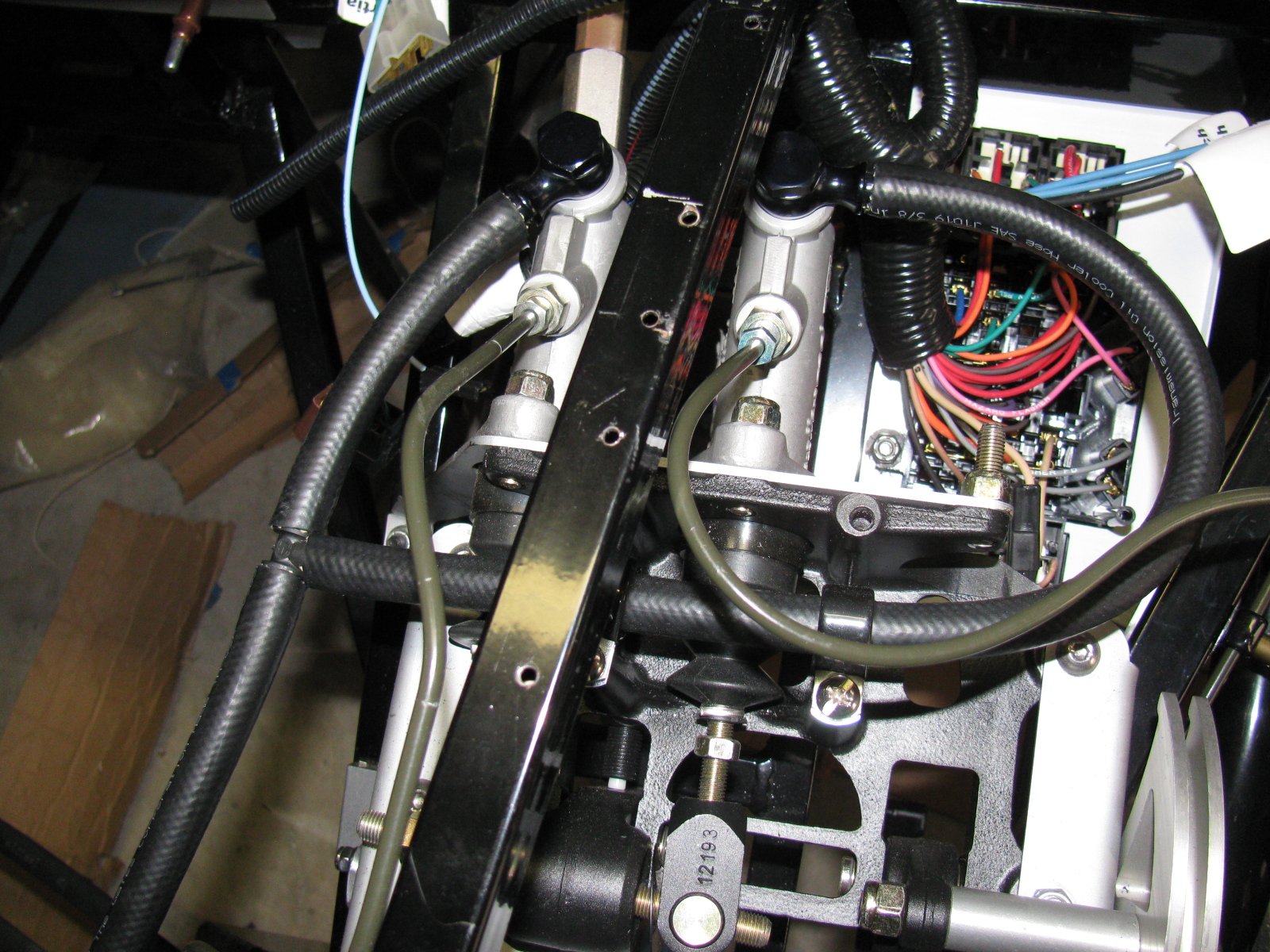
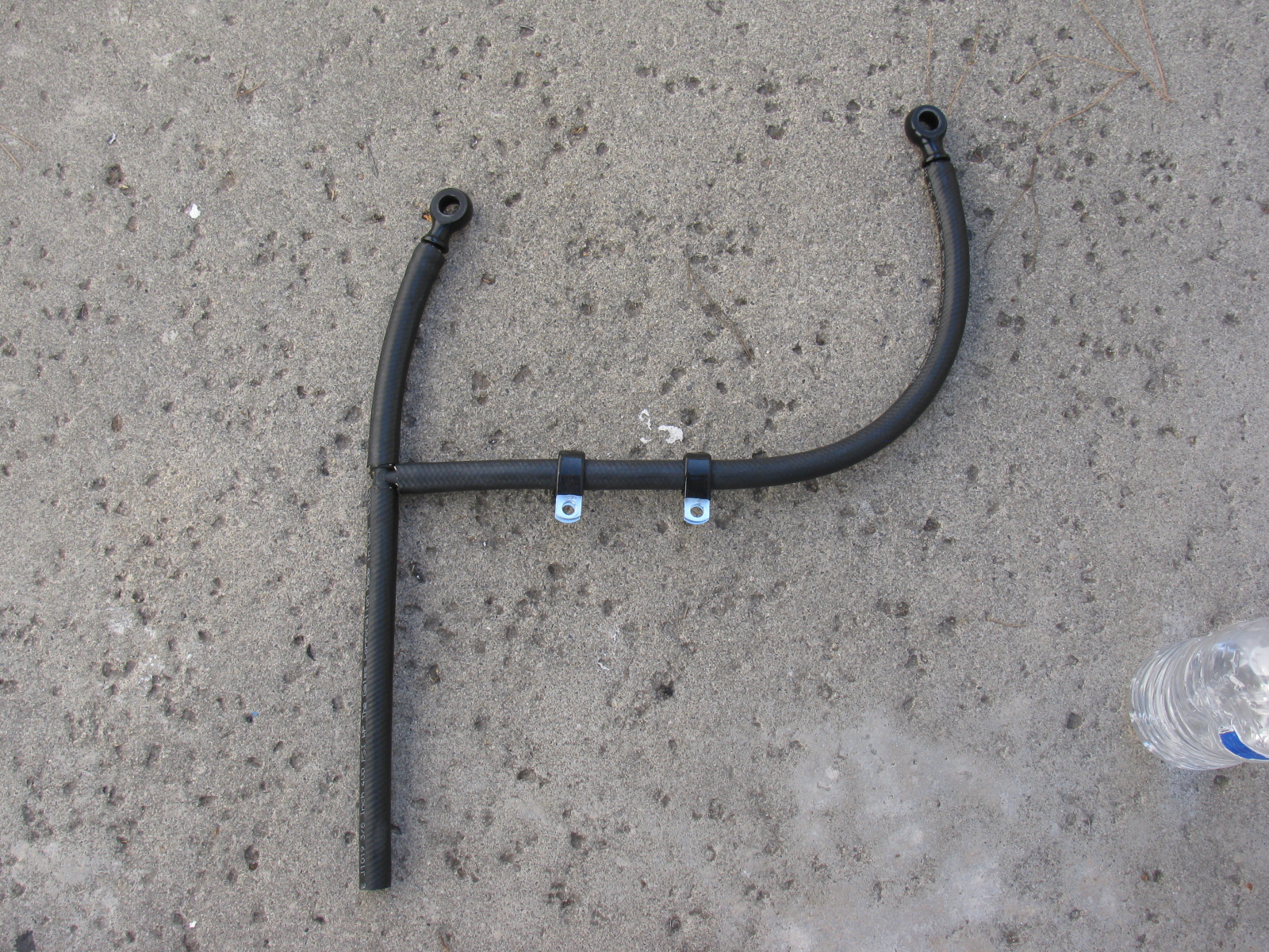
Next, I removed the “bad” brake hoses originally from the Complete Kit and replaced them with the proper red hose from the third technical bulletin from Factory Five Racing. This is the hose going from the reservoir to the master cylinders. The new hose is much softer and easily slipped over the fittings. I hope they won’t leak. We will find out soon when I fill and bleed the system.


I also started to look at engine hoist options – I want to drop the engine in SOON!
Since the engine is in the middle of my garage, I really need to accelerate my building, or at least, get my chassis ready for engine installation.
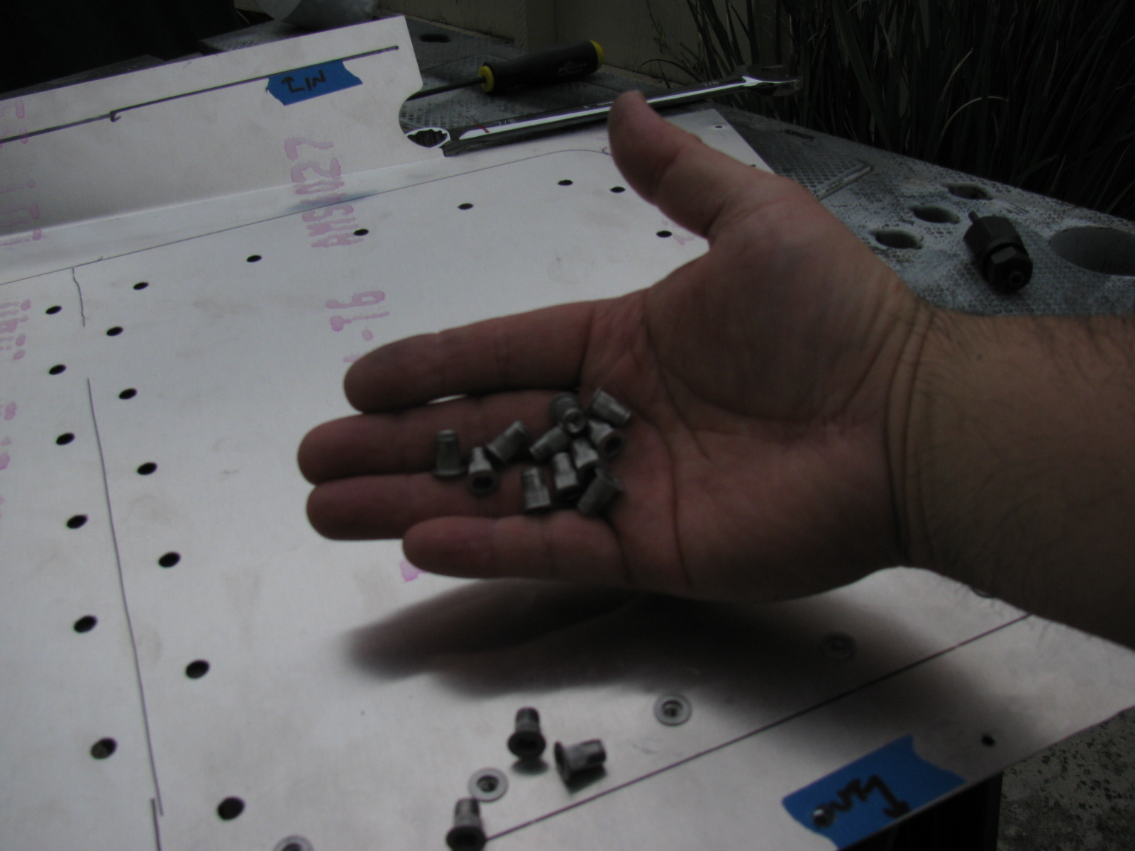
I looked at my cookie sheet heat shields and the mounting locations filled with 8-32 riv-nuts, and thought – shoot, the riv-nuts actually have a shaft that might be used as stand-offs for the shield plates. So I checked the length, and the threaded shafts are about a quarter-inch long, enough to be used as a spacer between the firewall and the heat shield. I may add another quarter-inch in certain places, if there is room.
So I spent a few hours removing all of the riv-nuts I installed a few weeks ago. Good thing I bought several hundred from McMaster-Carr. . . .
At least I am an expert on installing and extracting riv-nuts now.
Rivet Nuts and the Rivet Nut Tool
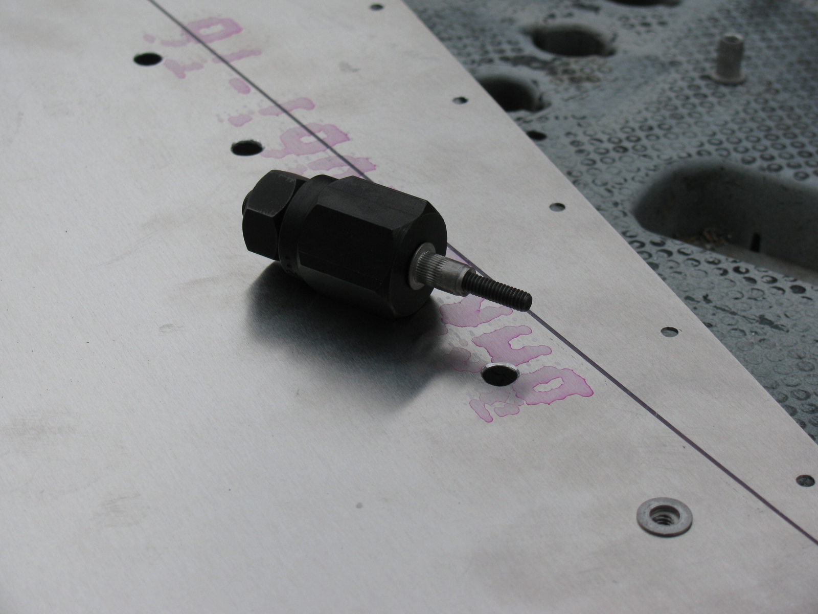
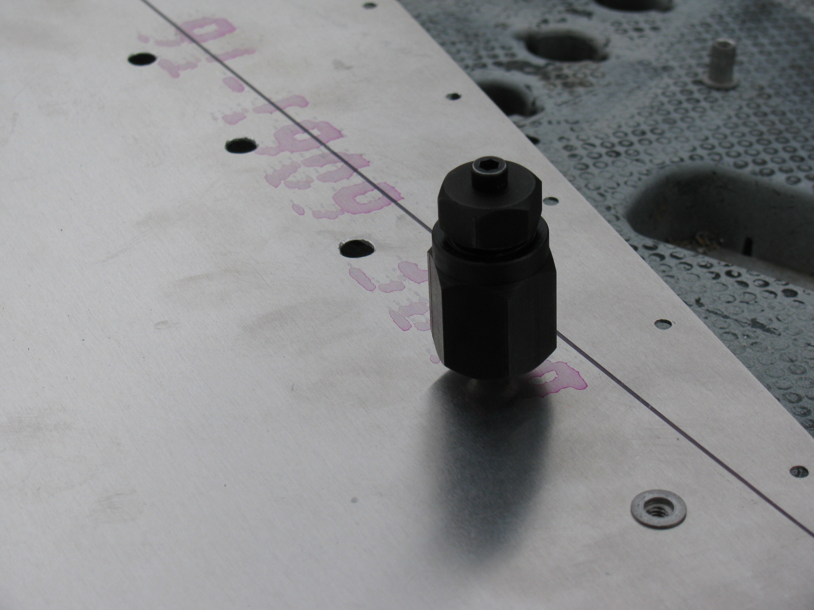
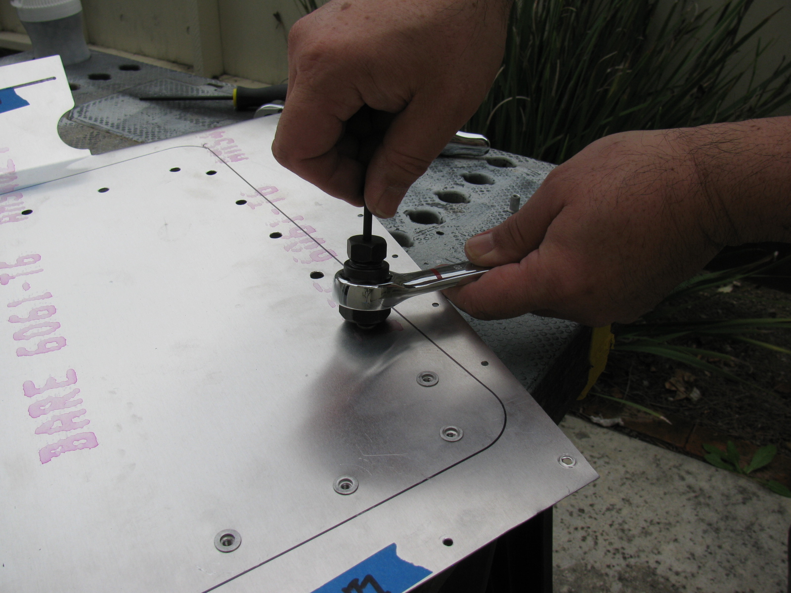
Here are some pictures of the riv-nut tool from McMaster-Carr and how it is used. Riv-nut fasteners are very handy if you need a threaded hole installed into a blind location, or when you do not have access to the back side of a mounting surface. I will use these fasteners for hatches and compartments in the trunk area of the Type 65 Coupe.
McMaster-Carr information
Wrench-drive rivet nut installation tool for 10-24 and 10-32 thread: 96349A203
Wrench-drive rivet nut installation tool for 8-32 thread: 96349A152
Wrench-drive rivet nut installation tool for 6-32 thread: 96349A101
Aluminum heavy-duty rivet nut, 6-32 internal thread, .080″-.130″ material thickness, packs of 25: 94020A315
Aluminum heavy-duty rivet nut, 8-32 internal thread, .080″-.130″ material thickness, packs of 25: 94020A323
Aluminum heavy-duty rivet nut, 8-32 internal thread, .020″-.080″ material thickness, packs of 25: 94020A319


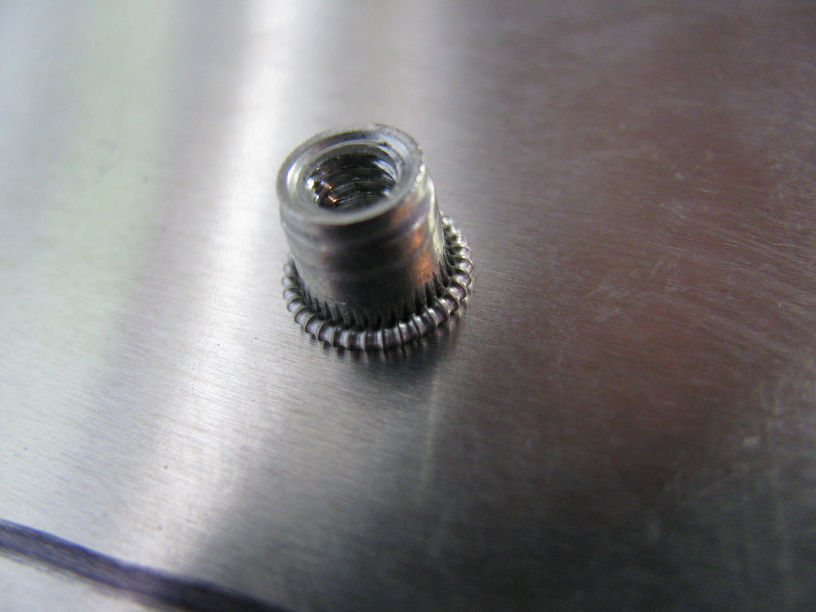
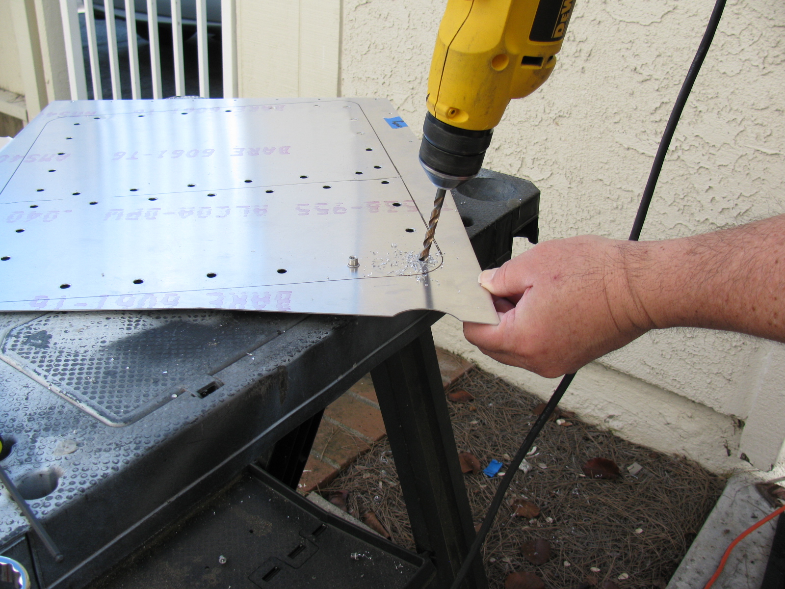
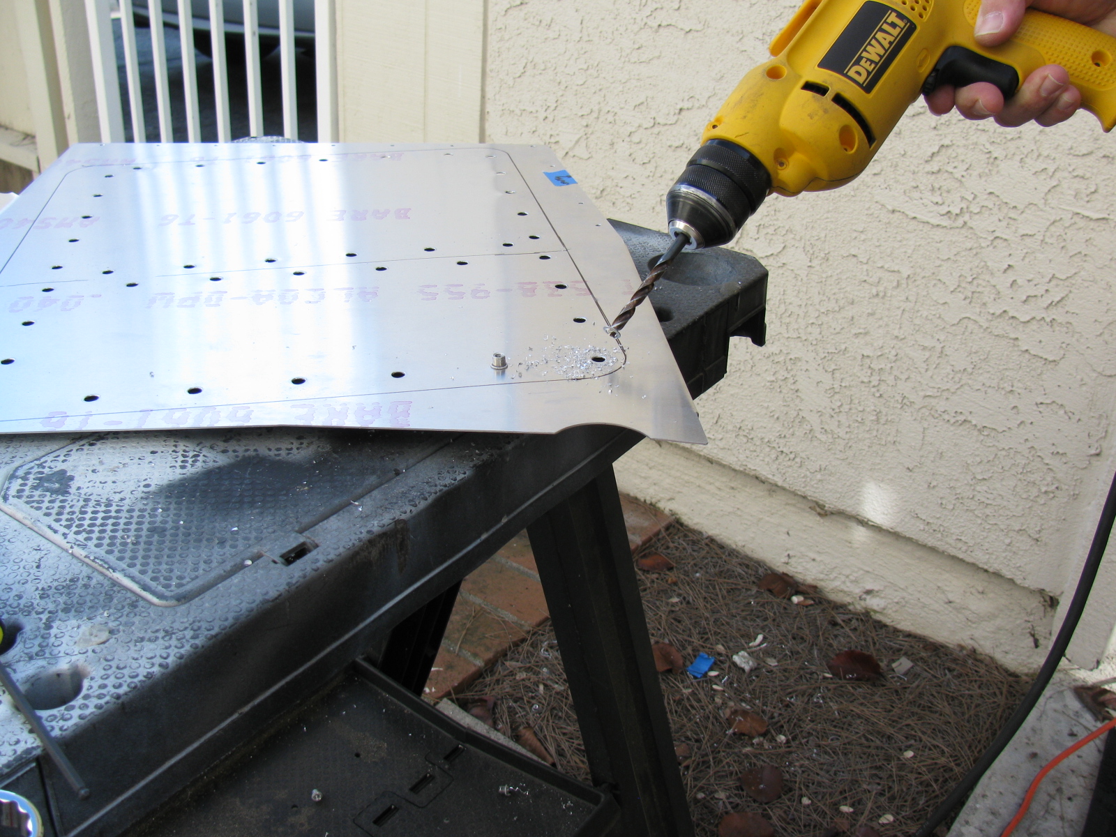
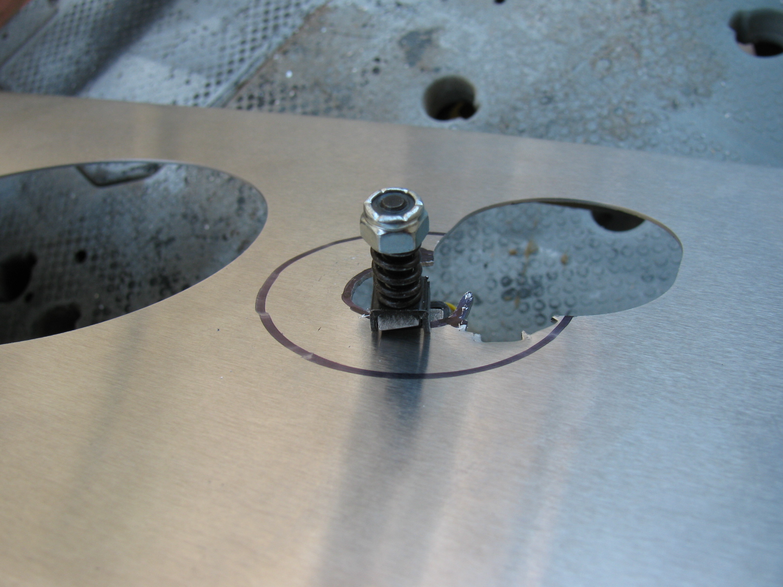
Above left – a picture of a properly installed riv-nut, viewed from the reverse (back) side. At right, a riv-nut improperly installed, viewed from the face (front) side. This one must be removed by drilling the riv-nut out. Below left, use a twist drill slightly smaller than the mounting hole, in this case, a 1/4-inch bit is being used to drill out the riv-nut. By slightly rocking the drill, the riv-nut will break apart and, usually, just fall out of its hole.


Give Me a Brake: The Wilwood Pedal Box
The pedal box is a challenge to install with the Factory Five Racing Assembly Manual, revision 3E, July 2011 – since there are no assembly instructions for the Wilwood Complete Kit pedal box.
Fortunately, a dedicated Type 65 Coupe builder named Chris has an excellent photo album of his Coupe build, with many detailed images. Without his documentation – it would have been impossible to assemble this part of the kit. Take a look at cbergquist1’s photostream on Flickr.
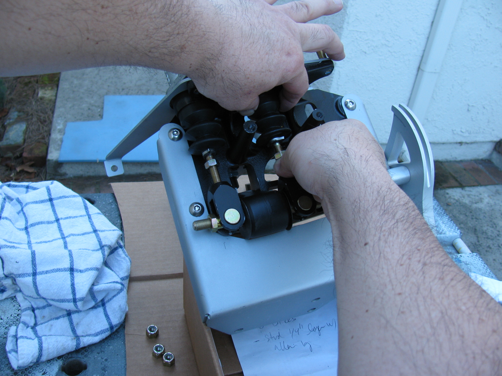
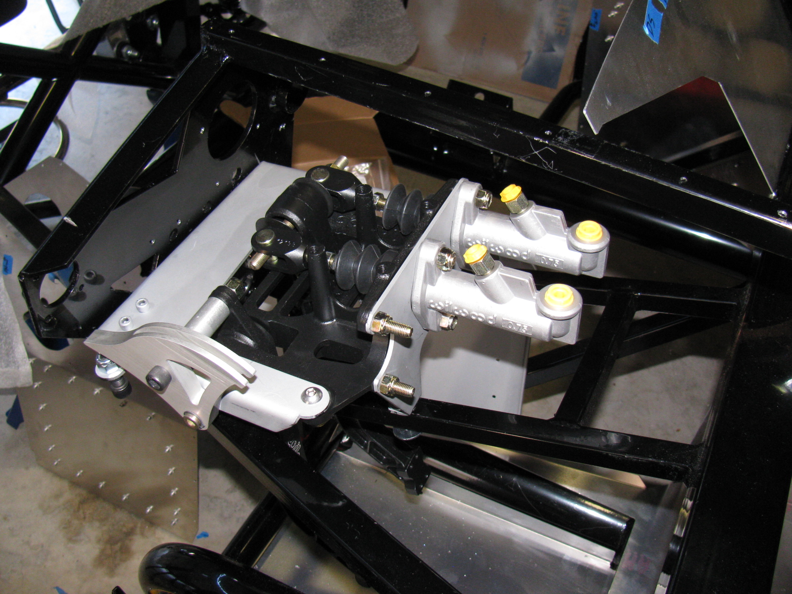
Here are some pictures of my pedal box, including a trouble spot I ran into, and how I had to fix it. . . .


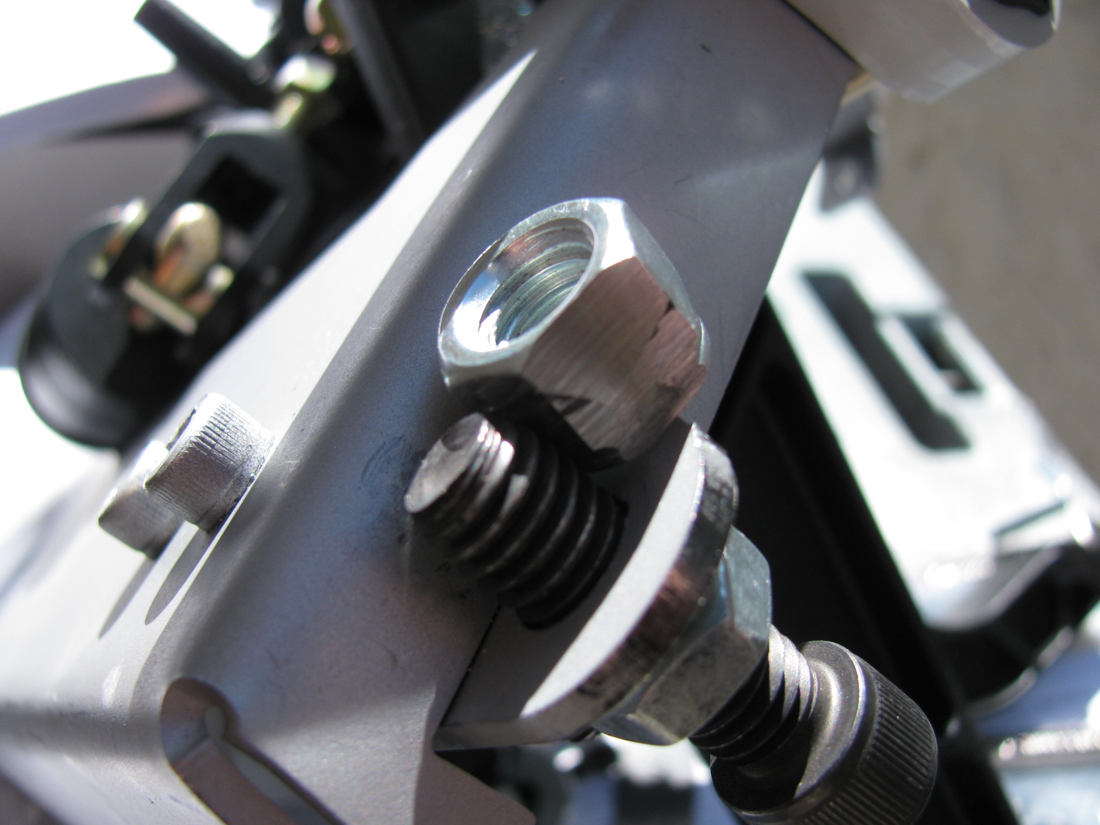
This is the clutch quadrant adjuster (above). This Nylok had to be ground down to fit properly. The hole in the adjuster plate is too close to the master cylinder mounting plate. A better solution would be to eliminate the Nylok altogether and thread the small plate. Then the lock nut and Allen bolt are used to make clutch travel adjustments.


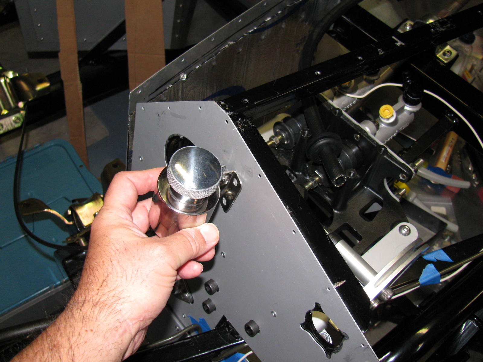
Now I have to find a place to mount the master cylinder reservoir. There are some rare posts about this, but most of them are for the Factory Five Racing Roadster.
I think I will mount mine at or near the peak of the driver’s side footbox/firewall. This location should be away from too much heat, and should be in the clear for fluid bleeding, checks and re-filling. We will see. . .
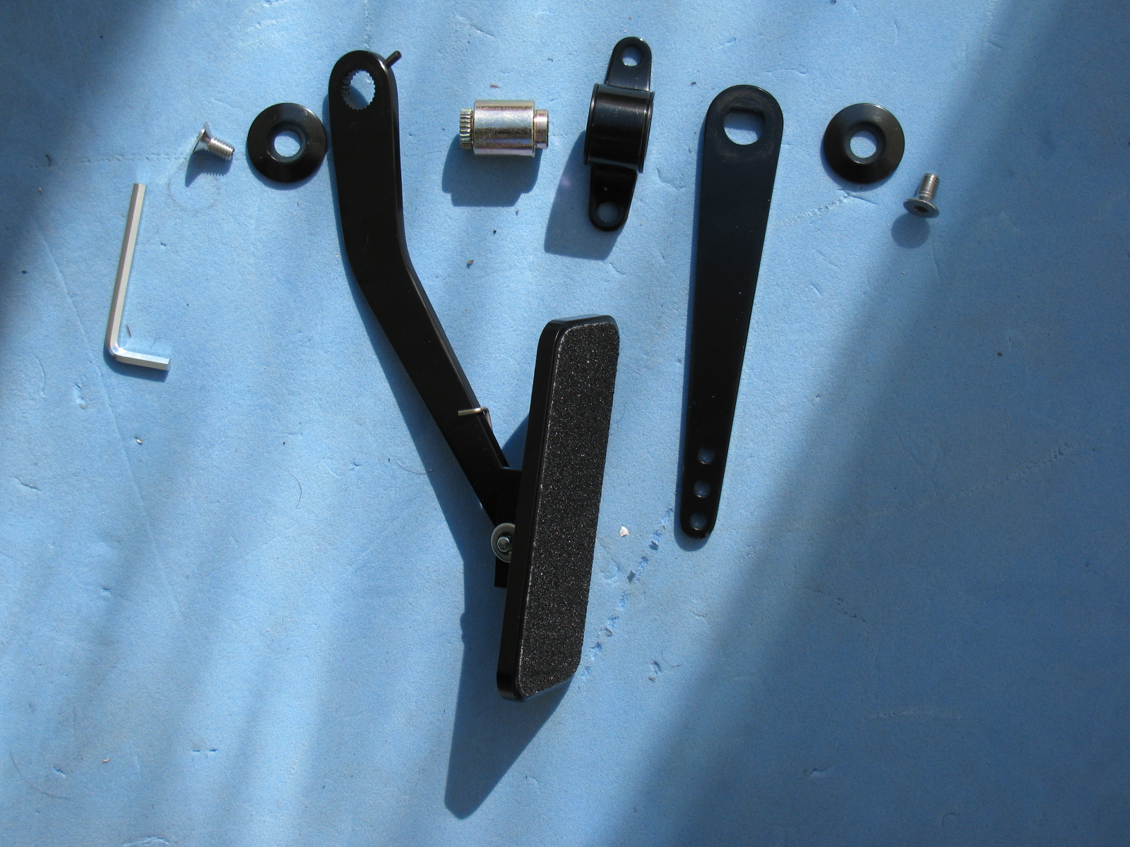
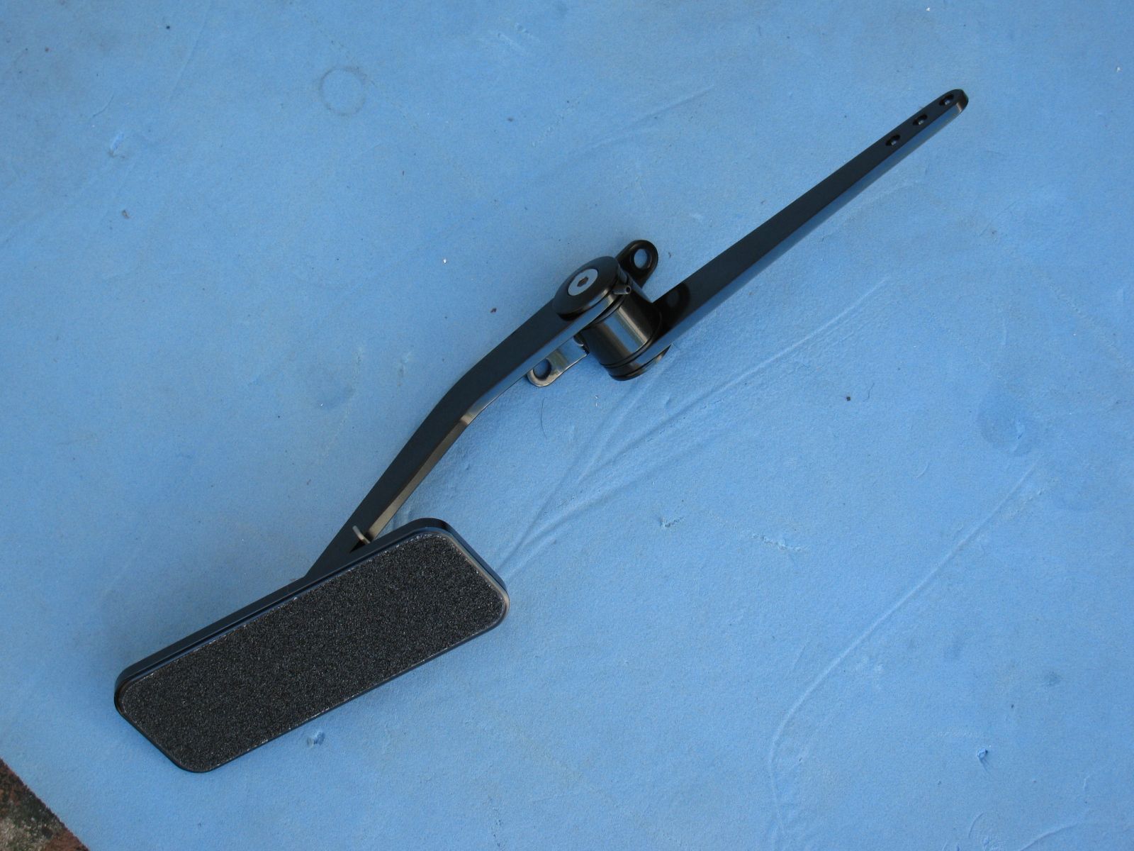
The Gas Pedal


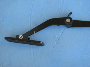

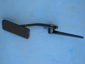
Part of the pedal box area is the accelerator pedal. Again, instructions are very skimpy on how to put this thing together. Here are some pictures of the gas pedal parts and how to dis-assemble the unit as it comes out of the box, and where it mounts onto the firewall area. Adjustments for the pedal box and accelerator pedal will happen later.
I am working on several things on the car at the same time. Whenever I get stuck or run into a problem, I move to a different part of the car to build. At some point, things will meet up and progress in a more orderly fashion, but at this stage, nothing is complete.
This Factory Five Racing Coupe project is consuming my life. Even when I am sleeping, I have dreams about the car, the building process or driving the car.
But lately I have been having nightmares about the car….
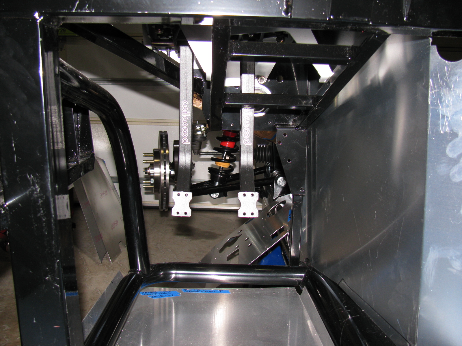
Front Suspension Re-Do
I managed to install a part on the front suspension upside down and backwards. Of course, like a lot of automotive things, in order to get to that part, a lot of other parts must be removed first. Some parts required a tremendous amount of torque to install. These are parts that should never “fall off” like anything in the front suspension and wheel mounts.
So, one of the chores I had to do was to remove the front wheel bearings and hubs. I tried to remove the mechanical lock nut with my ratchet, but it would not budge. This is a good thing, since this one nut fastens the wheel to the car. Installing these parts required several very hard whacks with my plastic hammer and several Rated R and X words and phrases. I could not help but wonder how those parts would come off if I ever needed to repair or replace them.
Reading the forums made me lose a lot of sleep, since it seems that a lot of fellow builders have had trouble with this part, too. I bought an AC-operated impact wrench and some very large (36mm) impact sockets to remove the hub nuts. As a back-up, I also bought a large 1/2-inch drive breaker bar and a piece of pipe to increase the torque if needed.
I called my friend Larry over for some assistance.

Surprisingly, the breaker bar made the hub nut come right off. Even more surprising is the condition of the spindle where the wheel and bearing mounts – it still looks brand-new and without any distortions or scratches.

After purchasing the impact wrench, Larry sent me an e-mail advising me to not use an impact wrench on the front hubs, because this may damage the wheel bearings. I took this advice, and returned the impact wrench. Good thing I did not open the box. . .
Interior (Cockpit) Aluminum Panels
After the problem with building the IFS, I decided to “dry-fit” all parts from now on. This way I can verify everything is correct – or fix things that are wrong – before tightening the parts into place.
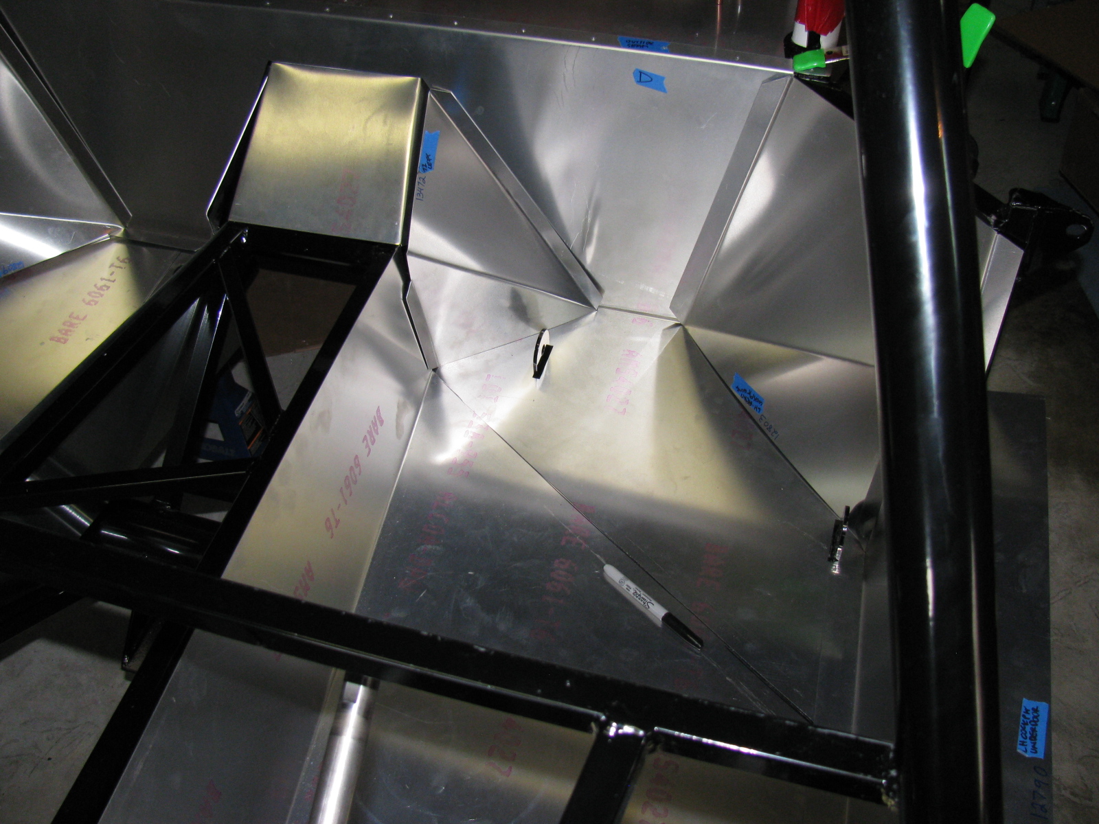
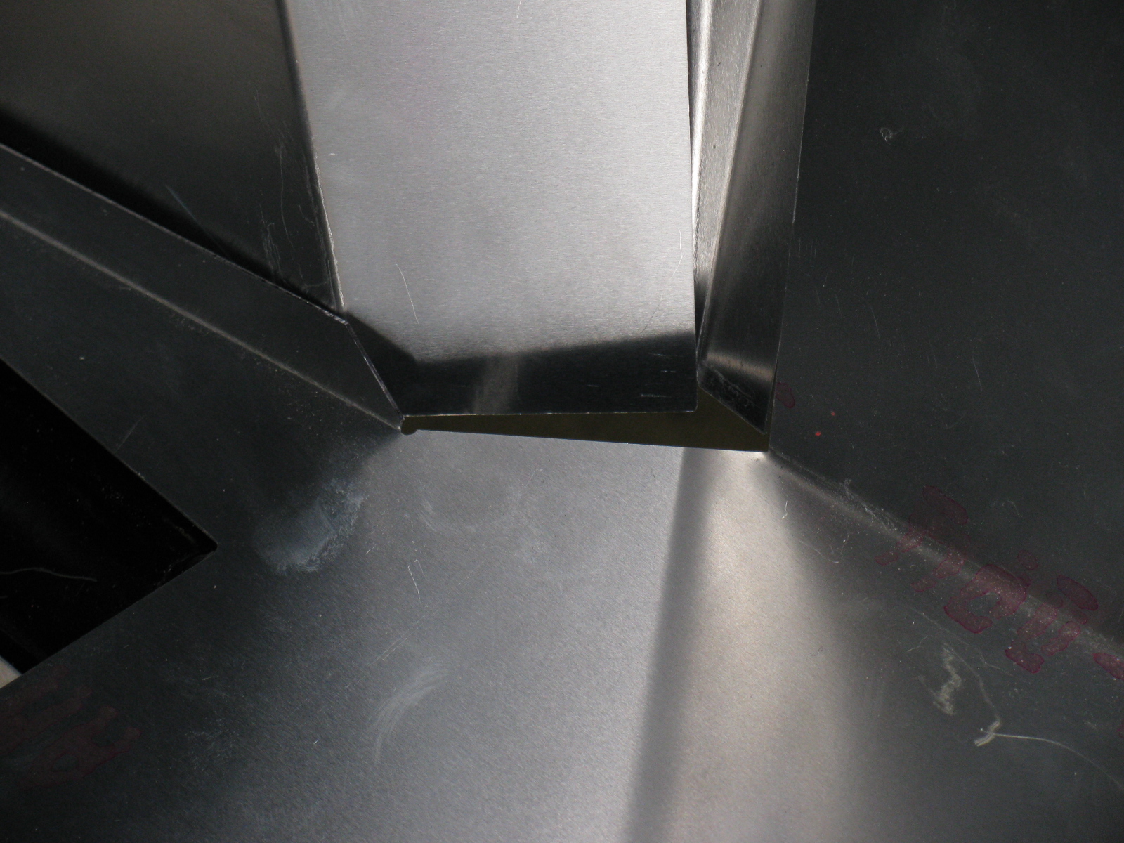
I decided to do some more work on the interior sheet aluminum. Compared to some of the other tasks, fitting the aluminum is easy. I made some diagonal cuts along the floor to make the parts fit easier, and to prevent scratching the nearby interior panels. By cutting the single large pieces into multiple smaller pieces, they will drop into place, rather than bend and scrape into place – preserving the painted surfaces.

The seams and bend directions are hard to see in these pictures, the aluminum sheets do not provide enough contrast. I may use masking tape to show where the parts go and where the seams meet next time. As I said, this is the first attempt to fit the cockpit aluminum. Based on old Factory Five Racing forum posts, it looks like my aluminum panels have been improved somewhat. The only poorly fitting space is this big gap on the driver side, right at the corner of the transmission tunnel.

I may either trim the mounting tab behind one of the panels, or just install some sort of patch over the top. Overall, though, this Generation 2 Coupe seems to have better-fitting interior panels, so far.
Dashboard
Here is an example of something gone wrong —

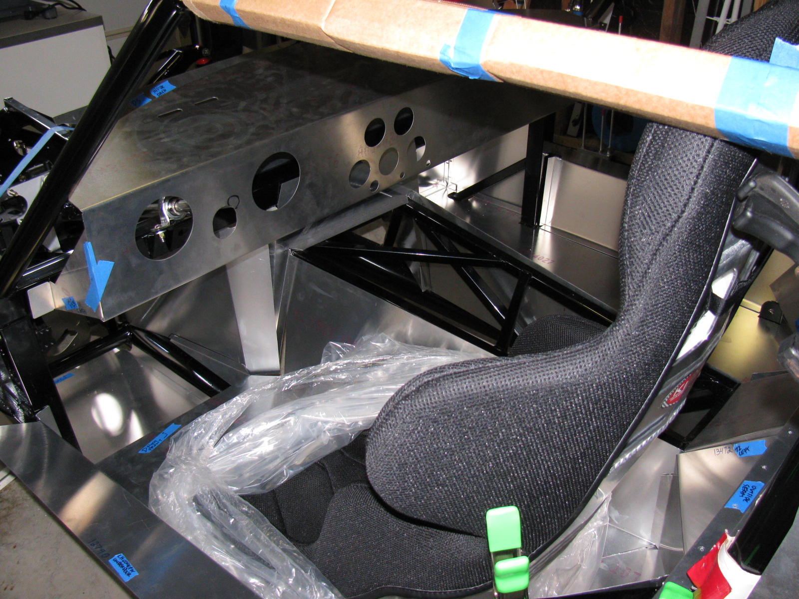
Notice the odd-shaped hole for the steering column? The mounting location for the steering shaft is not straight and parallel along the ladder structure in the driver side footbox and clutch quadrant. As I examined all the parts in this area, I believe the factory did this because of an interference issue with the brake pedal. If the steering column shaft were to run parallel to the ladder structure, it would block the brake pedal actuator. Moving the mount – but not compensating for this on the dashboard panel – makes this problem look worse than it may be.
I used a nibbling tool, a round file and a sanding drum to enlarge the hole for the steering shaft.


A popular modification to the dashboard is to cut along the bend, making the one long piece dashboard into two long pieces. This enables access to the inside of the dash from the top as well as the front, and will make installing and maintaining dash components such as gauges, air conditioner and plumbing much easier. I will make this cut at the next build session.
I just have to figure out a way to disguise the big and ugly hole in the dashboard. . .
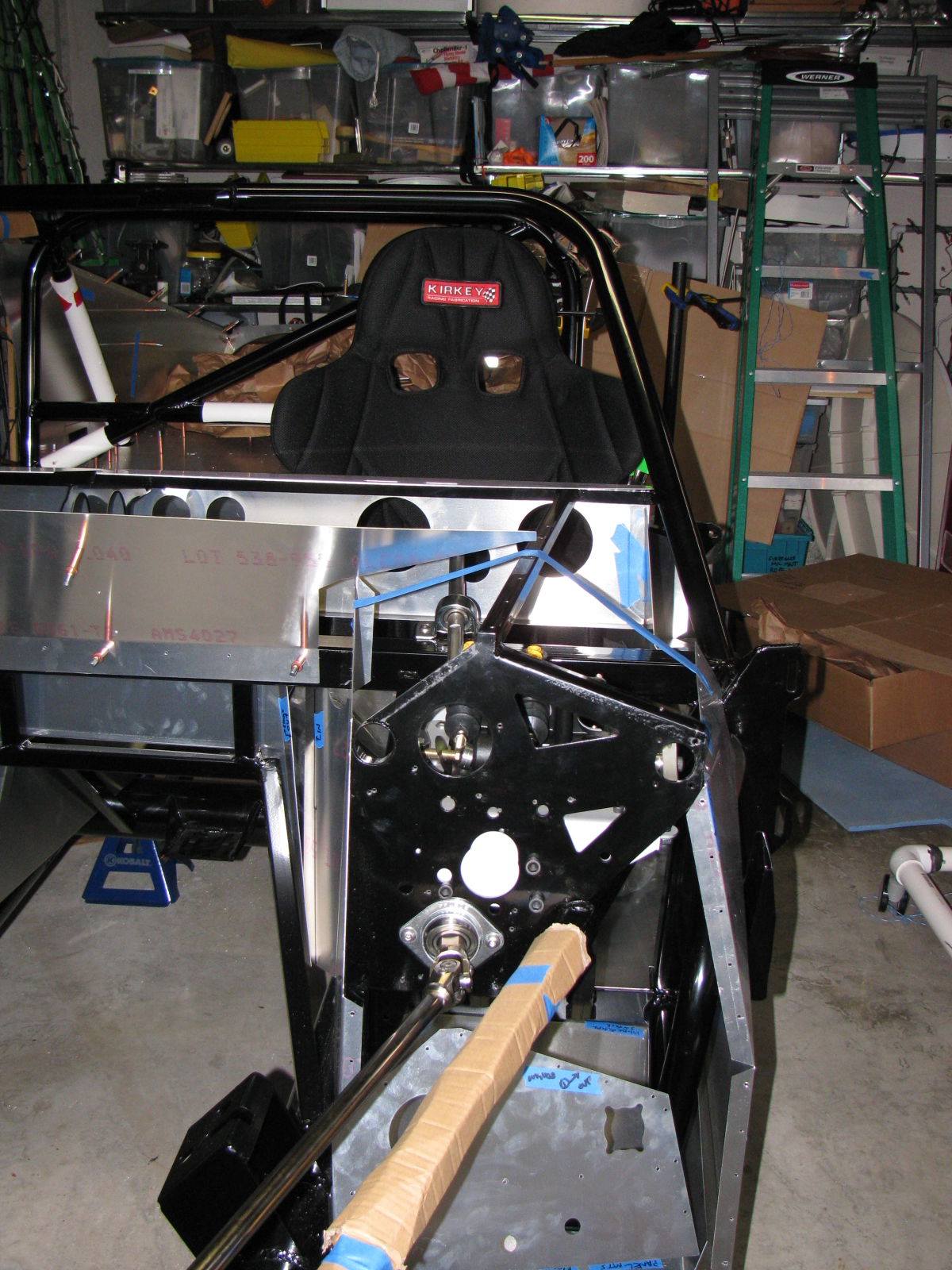
The Racing Seats
I placed the Kirkey high-back racing seats to see how it fits, and although the steering wheel is a bit toward the passenger side, I think it will be all right.


Clutch Quadrant and Pedal Box
Many Coupe builders owe a lot to a guy named Chris, who has documented his Type 65 Coupe build experience with lots of pictures. (I added a link to his flickr photostream in the Automotive Links section.) The Factory Five Racing assembly manual left an entire section out for us Complete Kit builders. There are no instructions for the Wilwood pedal box and clutch quadrant assembly. Thanks Chris for sharing your images!
Anyway – here are some pictures of my Wilwood pedal box and clutch quadrant. I do not have too many fitment issues here, except for the mounting points to the 3/4-inch tubes – I will have to wedge the mounts at the firewall in order to securely mount the pedal box to the ladder structure. I painted my footbox mounting plate with silver Rust-Oleum BBQ paint. I wanted to do a test to see how the color came out and how durable the finish is. I like the color, it is much better than the raw steel and hopefully will prevent any rust from forming inside the car.


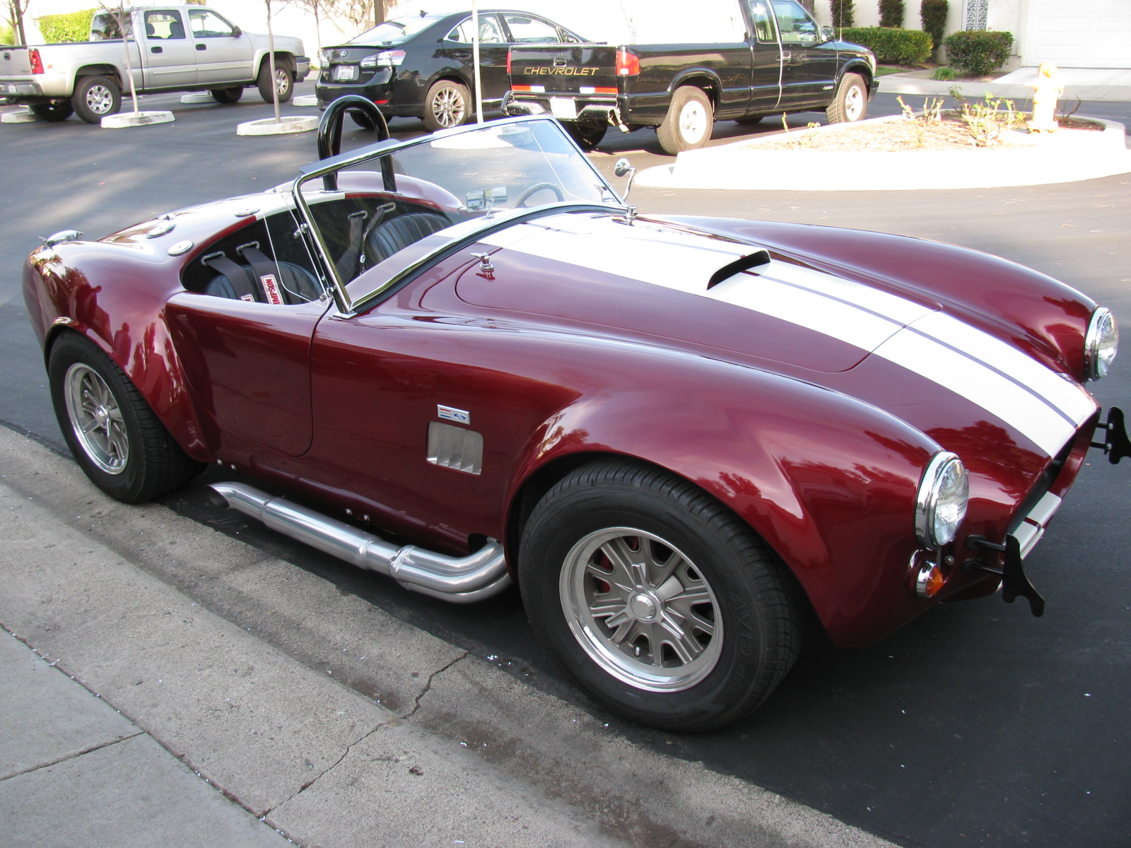
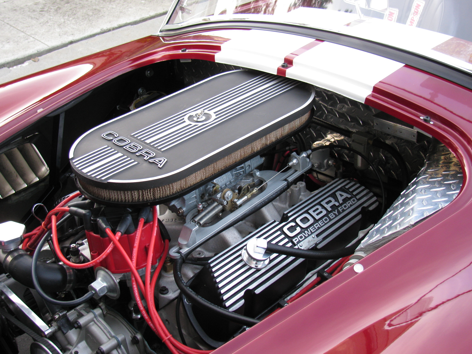
A Roadster Driver Visits
Rick, a neighbor and Roadster owner, stopped by for a visit. Here are some pictures of his very nice car. Rick did the paint job by himself in his garage – I am very impressed with the way the finish came out – take a look!