Archive for the ‘upper control arms’ Tag
It has been raining off and on all week, and continued through this past weekend. This is a good thing, since I can avoid yard work, and even better – I can spend more time in the garage. However, the garage has been cold, 40 degrees F. This pretty much kills any plans for painting anything.
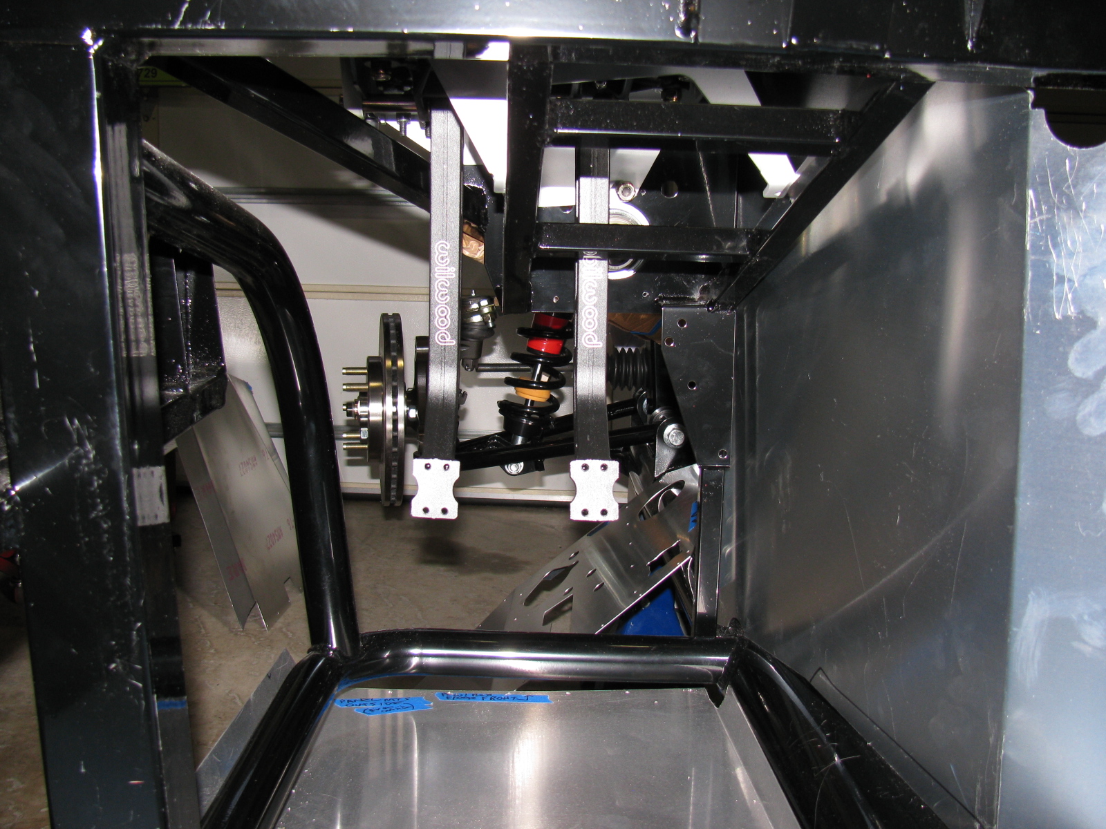
Since the 80 pound metal medicine ball – also known as the pumpkin, center section, differential and other names – is re-sealed and mounted, the rest of the independent rear suspension assembly is going smoothly.
Learning something from the front suspension experience, I decided to assemble all the pieces on one side of the car first, and only hand-tighten the fasteners. This will prevent time-consuming error-fixing.
There is a saying on the Factory Five Forums – it goes something like, “if there aren’t any pictures, it didn’t happen.”
So, since there aren’t any pictures of the parts I installed backwards, it didn’t happen, right?
Let’s just say the assembly manual lacks good pictures to help us understand how to orient things properly. Many of the pictures are cropped too tightly, and do not show the nearby parts to help us visualize relationships to other parts or reference points.
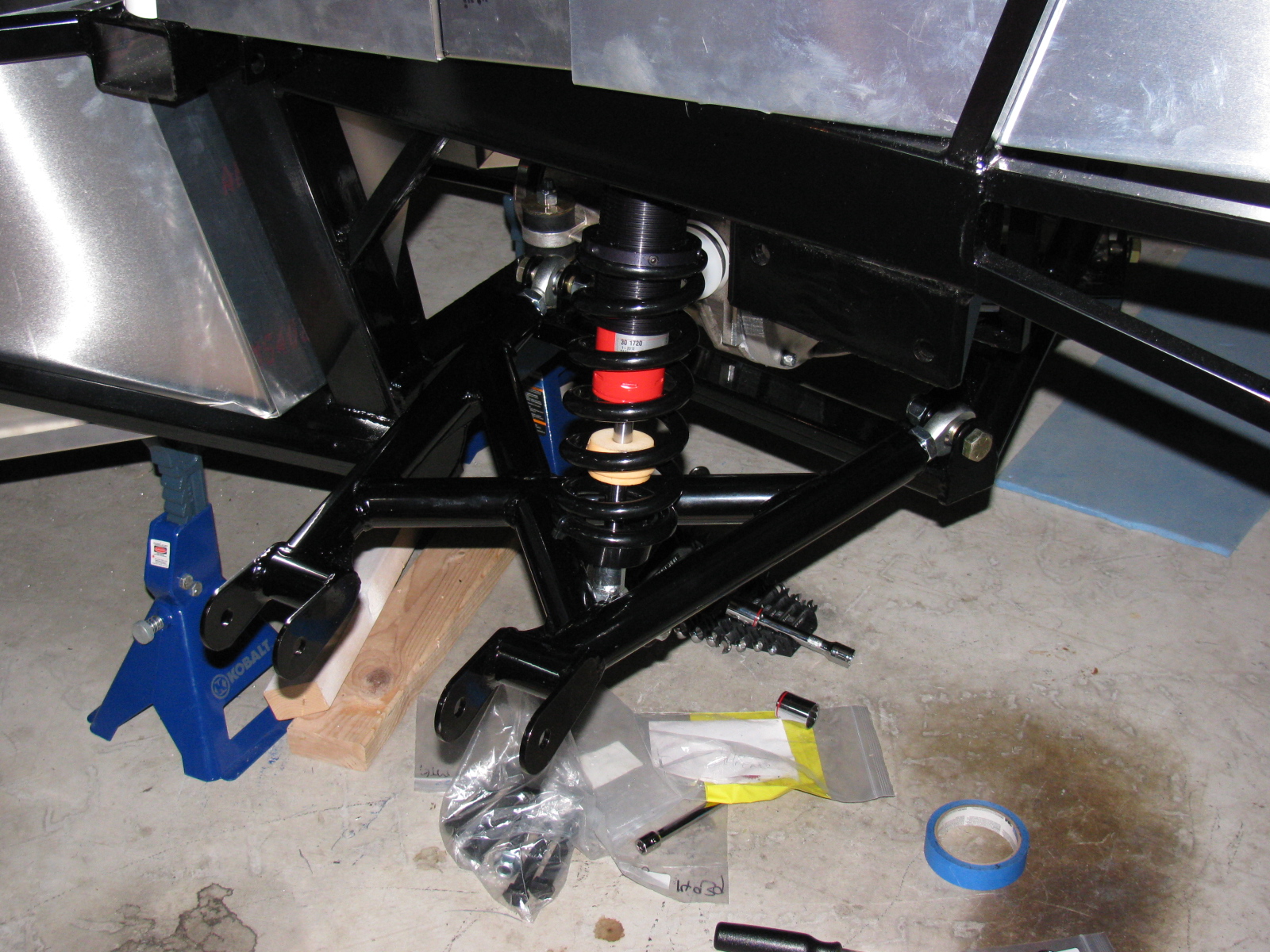
Here are some pictures of the driver side lower control arm and coil-over-shock being installed. . .


While mounting the lower control arms, I kept dropping a stack of small shims (they look like thin washers) needed between the chassis mounting tabs. Of course, since they are round, they roll all over and under the strangest places. I had to use a small magnet to retrieve several of them.
The magnet made me think of a great way to hold and install these small shims on the mounts. Take a look. . .

The little magnet holds the stack of shims together, and by wiggling, pushing and pulling on the suspension parts, the bolt will slide through the stack. This works great, and it makes me feel happy rather than mad while underneath the chassis.
Of course, this only works if the parts are ferrous. The aluminum spacers are another story.
The spindles, upper control arms, and CV axles are next. Stay tuned . . . .
I am working on several things on the car at the same time. Whenever I get stuck or run into a problem, I move to a different part of the car to build. At some point, things will meet up and progress in a more orderly fashion, but at this stage, nothing is complete.
This Factory Five Racing Coupe project is consuming my life. Even when I am sleeping, I have dreams about the car, the building process or driving the car.
But lately I have been having nightmares about the car….
Front Suspension Re-Do
I managed to install a part on the front suspension upside down and backwards. Of course, like a lot of automotive things, in order to get to that part, a lot of other parts must be removed first. Some parts required a tremendous amount of torque to install. These are parts that should never “fall off” like anything in the front suspension and wheel mounts.
So, one of the chores I had to do was to remove the front wheel bearings and hubs. I tried to remove the mechanical lock nut with my ratchet, but it would not budge. This is a good thing, since this one nut fastens the wheel to the car. Installing these parts required several very hard whacks with my plastic hammer and several Rated R and X words and phrases. I could not help but wonder how those parts would come off if I ever needed to repair or replace them.
Reading the forums made me lose a lot of sleep, since it seems that a lot of fellow builders have had trouble with this part, too. I bought an AC-operated impact wrench and some very large (36mm) impact sockets to remove the hub nuts. As a back-up, I also bought a large 1/2-inch drive breaker bar and a piece of pipe to increase the torque if needed.
I called my friend Larry over for some assistance.

Surprisingly, the breaker bar made the hub nut come right off. Even more surprising is the condition of the spindle where the wheel and bearing mounts – it still looks brand-new and without any distortions or scratches.

After purchasing the impact wrench, Larry sent me an e-mail advising me to not use an impact wrench on the front hubs, because this may damage the wheel bearings. I took this advice, and returned the impact wrench. Good thing I did not open the box. . .
Interior (Cockpit) Aluminum Panels
After the problem with building the IFS, I decided to “dry-fit” all parts from now on. This way I can verify everything is correct – or fix things that are wrong – before tightening the parts into place.
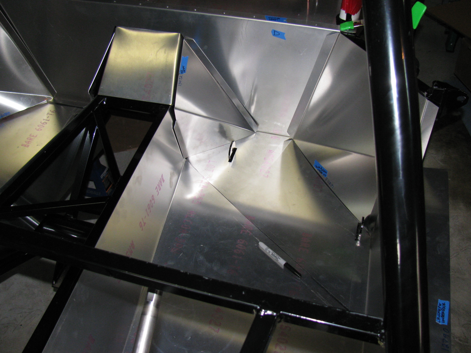
I decided to do some more work on the interior sheet aluminum. Compared to some of the other tasks, fitting the aluminum is easy. I made some diagonal cuts along the floor to make the parts fit easier, and to prevent scratching the nearby interior panels. By cutting the single large pieces into multiple smaller pieces, they will drop into place, rather than bend and scrape into place – preserving the painted surfaces.

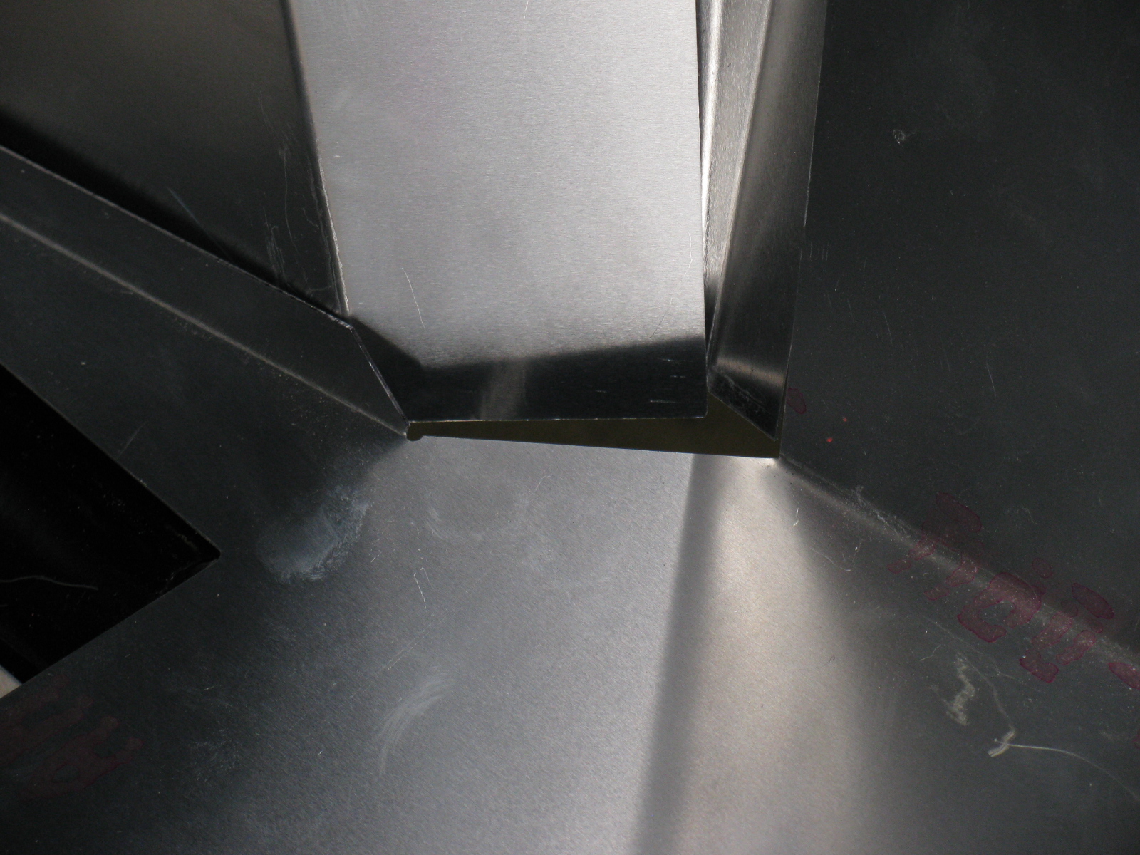
The seams and bend directions are hard to see in these pictures, the aluminum sheets do not provide enough contrast. I may use masking tape to show where the parts go and where the seams meet next time. As I said, this is the first attempt to fit the cockpit aluminum. Based on old Factory Five Racing forum posts, it looks like my aluminum panels have been improved somewhat. The only poorly fitting space is this big gap on the driver side, right at the corner of the transmission tunnel.

I may either trim the mounting tab behind one of the panels, or just install some sort of patch over the top. Overall, though, this Generation 2 Coupe seems to have better-fitting interior panels, so far.
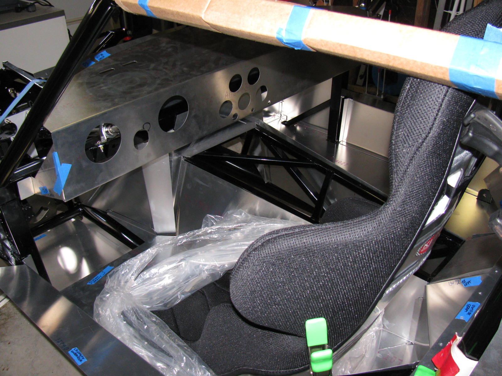
Dashboard
Here is an example of something gone wrong —

Notice the odd-shaped hole for the steering column? The mounting location for the steering shaft is not straight and parallel along the ladder structure in the driver side footbox and clutch quadrant. As I examined all the parts in this area, I believe the factory did this because of an interference issue with the brake pedal. If the steering column shaft were to run parallel to the ladder structure, it would block the brake pedal actuator. Moving the mount – but not compensating for this on the dashboard panel – makes this problem look worse than it may be.
I used a nibbling tool, a round file and a sanding drum to enlarge the hole for the steering shaft.


A popular modification to the dashboard is to cut along the bend, making the one long piece dashboard into two long pieces. This enables access to the inside of the dash from the top as well as the front, and will make installing and maintaining dash components such as gauges, air conditioner and plumbing much easier. I will make this cut at the next build session.
I just have to figure out a way to disguise the big and ugly hole in the dashboard. . .
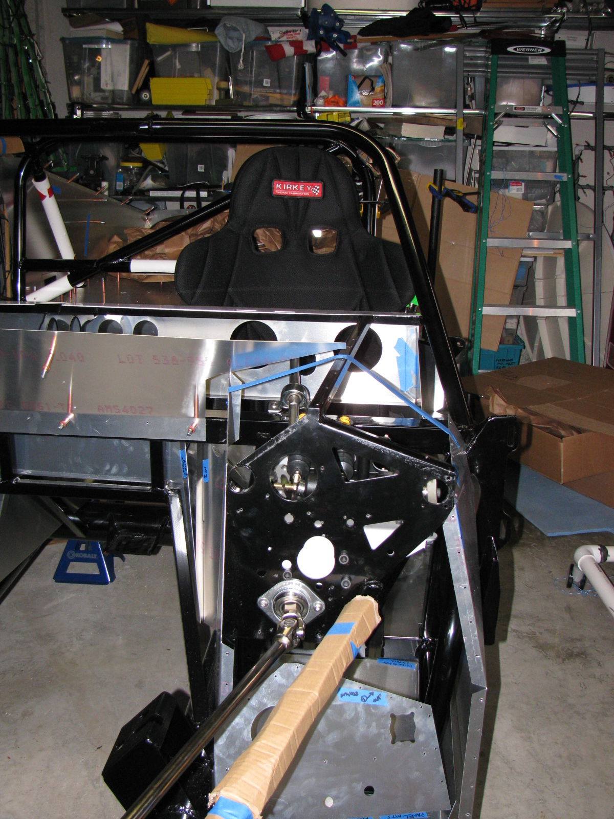
The Racing Seats
I placed the Kirkey high-back racing seats to see how it fits, and although the steering wheel is a bit toward the passenger side, I think it will be all right.


Clutch Quadrant and Pedal Box
Many Coupe builders owe a lot to a guy named Chris, who has documented his Type 65 Coupe build experience with lots of pictures. (I added a link to his flickr photostream in the Automotive Links section.) The Factory Five Racing assembly manual left an entire section out for us Complete Kit builders. There are no instructions for the Wilwood pedal box and clutch quadrant assembly. Thanks Chris for sharing your images!
Anyway – here are some pictures of my Wilwood pedal box and clutch quadrant. I do not have too many fitment issues here, except for the mounting points to the 3/4-inch tubes – I will have to wedge the mounts at the firewall in order to securely mount the pedal box to the ladder structure. I painted my footbox mounting plate with silver Rust-Oleum BBQ paint. I wanted to do a test to see how the color came out and how durable the finish is. I like the color, it is much better than the raw steel and hopefully will prevent any rust from forming inside the car.


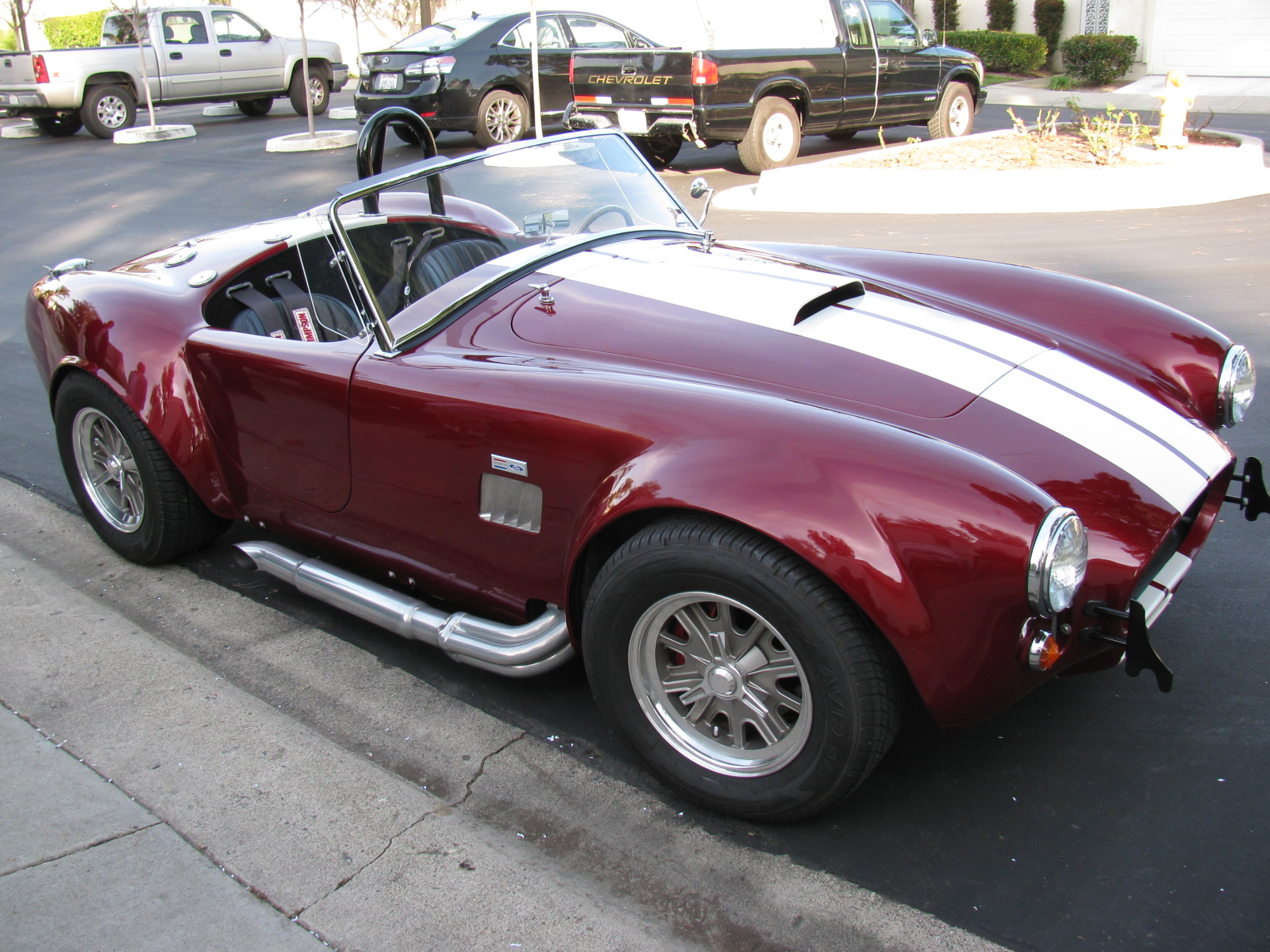
A Roadster Driver Visits
Rick, a neighbor and Roadster owner, stopped by for a visit. Here are some pictures of his very nice car. Rick did the paint job by himself in his garage – I am very impressed with the way the finish came out – take a look!


It’s been cold in the garage lately (50s-60s), but I wanted to get some more work done on the Coupe. My 302 is scheduled to arrive this month, but I have a lot of work to do before I can install the engine and transmission. This is one of those rare times when I can tell a supplier to take their time.
Back to this weekend’s update: What’s cookin’. When I lived in a small townhouse, I used to make a lot of meals in a Crock Pot, and noticed a few things: First, it was very handy to fill the thing up with various meats and vegetables, turn it on, go away for a few hours and dinner would be ready. Second, the smell was always wonderful. And third, it actually made the house a little warmer.
I decided this third effect of Crock Pot cooking deserved a try in my garage – and it worked. In the morning, I filled the Pot with my universal minestrone recipe and added some leftover spare ribs from the freezer. I call it “Spare Rib Minestrone.” The recipe appears at the end of this entry. It is roughly based on a minestrone recipe from Fat Free, Flavor Full: Dr. Gabe Mirkin’s Guide to Losing Weight & Living Longer. And it is pretty tasty. It made the garage a few degrees warmer, too. Here’s a picture. . .

Cooking in the garage – a tasty alternative garage heating method!
Halibrand-Style Wheels Arrived
The Factory Five Racing Halibrand-style wheels are BIG and beautiful. Wheels are 17 x 9 in front and 17 x 10.5 in the rear, and feature a spin-off hub. I am still not completely sure what tires will go on these rims, my preliminary choice is a set of Goodrich Sport-Comp 2 or something like that. This may change as I get a little farther along on my build.


The Steering Rack
I decided to see if I could finish the front end this weekend, especially since a lot of the back-ordered items arrived – I finally have a complete set of parts for my complete kit!
The steering rack is a non-powered unit made for the Mustang. Like many others, the mounting ears were too close together and I had to spread them out by a little over a quarter of an inch. I tried to use my pipe wrench trick, but the tabs are a little small and I wasn’t able to exert enough torque to move them. Doing some research on the Factory Five forums, I kept reading about people using a nut and bolt to spread mounting tabs wider. I finally found a post that included a picture of this, for future reference, it is located here, and I am posting photos and captions on my site as well so it may be easier to find. It’s a pretty neat trick, although no one says anything about the mounting tabs springing or bending back into their original position – you have to “over-bend” the tabs in order to make the part fit.
Here is my version of the mounting tab spreader tool using threaded rod, washers and nuts – I used 1/2-inch all-thread, since the 3/8-inch rod seemed a bit flimsy:

This really didn’t work too well, the tool needs another nut to hold it securely.

Like this

In the photo above, the open end wrench is being used to spread the mounting tabs outward. If the mounting tabs need to be smaller/tighter, move the washer and nut to the outside of the tab, and tighten the nut – squeezing the tabs closer together.
For the steering rack, I ran into another problem – that turned out to be a non-problem. As you can see here, after spreading the tabs out, the rack fits between the ears – but the holes on the passenger-side need to be moved about an eighth or a quarter of an inch to the left. After thinking about how long this will take using a rattail file, I took a break and thought about the steering rack. The driver’s side mounting tabs had a slot on one side – how come I am not able to move the rack over towards the driver side of the chassis?
The answer is, of course, yes, the slot is just enough to make the rack fit nicely. I used a punch and a mallet to move the rack into position. Success!

Compare the hole on the left (I used silver marker to show where to enlarge the hole) and the slot on the right. No reaming needed – I used a punch and a mallet to move the steering rack into place.
So now the tie rod ends have to be connected to the steering arms. But here is another problem – the driver side tie rod is too long – can I just get a hacksaw and cut off about an inch, as shown by the blue tape?

The driver side steering rack tie rod seems too long – but wait – something is amiss. ..
I decided to stop the steering rack installation at this point and get some answers before cutting the tie rod – because, as Norm Abram always said, “Measure twice, cut once.”
I came across the Summit Racing – Factory Five Racing Roadster build today – and there is a nice picture of the steering rack-tie rod connection posted here – this is for a Roadster, but I think the Coupe shares the same configuration. I have to give F5R a call to verify something – in the Roadster build, the steering tie rod to steering arms are upside down compared to my “dry fit” – Do the Coupe tie rods mount the same way? Also, the Summit Racing car has two lock nuts for each tie rod – my kit came with one lock nut for each side. The manual does not show the ends of the steering rack – poor photo-cropping.
Getting the Shaft
I did some test-fitting of the steering shaft – after some head-scratching moments, I figured out that I needed to remove the adapter that came with the lower end of the steering shaft, and replace it with another one, from another box of stuff. The length is just right, I have seen some early posts about the steering shaft being too long.
But I ran into another problem – the shaft does not come through the dashboard in the correct position. It is not as bad as some others I have seen, but still is quite a ways off. I am not sure if I can just cut the dashboard hole bigger to allow the shaft to come through, and patch the spaces or – what. More fiddling is needed.
Floor and Footbox Fitting – Passenger Side
I decided to do some more sheet aluminum work – this time, fitting the passenger side floor and footbox. Using the same technique as the trunk floor, I cut the passenger floor into three pieces. After the cutting, I noticed that I could have done this with only one cut, but the three pieces will be OK. I kept the left side un-cut, since it may be seen when the car is done. (I am not sure if I will apply paint or put carpet on the transmission tunnel area yet.)
At this point, everything is being held in place with Cleco pins. I want to test-fit, trim, drill and de-burr all the aluminum panels first, then apply paint – or powder coat them.
So although I think I did a lot of work on the Coupe this weekend, a lot of it does not seem to show. It still does not look like a car yet.

Cutting the passenger side floor.

Passenger side footbox – another jigsaw puzzle!
Something is Making Me Go – “Hmmmmmmm”
I noticed and wonder why the passenger-side side body mount area sheet aluminum is different from the driver-side side body mount area aluminum – take a look:

Driver side – side body mount near the footbox. . .

Passenger side – side body mount area, near the footbox – see the difference?
Here’s another look:

Driver’s side

Passenger’s side. . .
This is making me go, Hmmm. Or more like Arrrrrg.
Season’s Greetings
Somewhere during the weekend, I installed my Christmas lights. I decided to cut back this year, because of all the work I am doing on the car. My “Ho Controller” and box of new lights and other parts I bought last year will have to wait until next year. In the meantime, here is a shot of my display. One of my Universal Rules for events is: “Everything you setup must be taken down and put away.” So many people spend hours and days – or even longer – putting up such decorations. My setup: less than 10 minutes to deploy, and even faster to take down!

Before I forget – here is the Spare Rib Minestrone recipe:
Spare Rib Minestrone
Yield: 6 servings
1 Large onion, chopped
5 cloves garlic, smashed
2 celery stalks, diced
2 cups of chicken stock
1 28 oz can of crushed tomatoes
1 tsp oregano
1 tsp basil
1 can pinto beans
1tsp red pepper flakes
6 small red potatoes, diced
1 large zucchini squash
Some leftover spare ribs, with BBQ sauce
Put everything into the Crock Pot, with the leftover ribs on top, surrounded by the vegetables. Put the Pot on High for about 6 hours or until the vegetables are tender. Based on the Primo Minestrone recipe by Dr. Gabe Mirkin, MD in Fat Free, Flavor Full
I’ve been busy with work and other chores so haven’t had much time to work on the car and update these pages – but – here is a re-cap of the work done over the last few sessions.
The day after the Welcome BBQ, I built a PVC pipe dolly for the Coupe body. It is made of 1-1/2 inch PVC pipe, some Ts, some 90 degree elbows and some casters from the “As-Is” bin at the local Ikea furniture store. I chose the plastic pipe because I had some connectors and lengths of pipe leftover from some other project. If I were to do this over, I would have made the dolly with 2 x 4s.


Next, I removed all the sheet aluminum from the chassis, marking the outlines of chassis tubes underneath. This is done to indicate where to drill holes for the pop rivets that are used to mount the sheet material on the finished car. This went pretty smoothly – except for the trunk area. It reminded me of one of those mechanical puzzles – you have to warp the trunk floor upwards and then slide and pull it toward the front of the car and then through the roof section. Or something like that. It is a tapered shape. After scratching the area just behind the seats – where the roll bar attaches – I decided there had to be a better way to get the trunk floor in and out of the chassis – this would be more important later in the build, because I will paint the trunk area. I decided to cut the trunk floor in half length-wise. Later, I found some posts in the forums that mentioned this, so I kind of re-invented the wheel on this one.
I used my power jig saw and a fresh metal cutting blade for this. My long saw guide was in another garage, so I had to come up with an alternative straight edge – a really long power strip worked fine. I centered a line on the trunk floor, and made the cut. You can see the wax along the cut line, this lubricates the blade and helps prevent the aluminum from clogging the blade.


The independent front suspension (IFS) came next. The steering arms are on back-order, but I decided to start building this section. The parts are beautiful, nicely powder-coated black. Some parts have a neat little detail built into them – see the “5” on the front lower control arm? Sort of like the hardware version of an “Easter Egg,” if you know what I mean.

I ran into a small snag at this stage. The mounting points on the body for the lower control arm were slightly off. I solved this by squeezing the arm into place with a quick-clamp. Easy.

A similar, but more difficult puzzle for the upper and lower shock mounts. A pair of aluminum spacers is used to center the coil/shock assembly on their mounts – the spacers were too long. This is a common problem, and it is documented on the forums. There are several ways to correct this, and I combined several hints to solve my issue. First, the upper mounts were a total of one-quarter of an inch too tight. I padded the rear-facing mounting ear with a rag, grabbed it with a pipe wrench, and pulled. It was surprisingly easy to bend that mounting ear to make it fit.
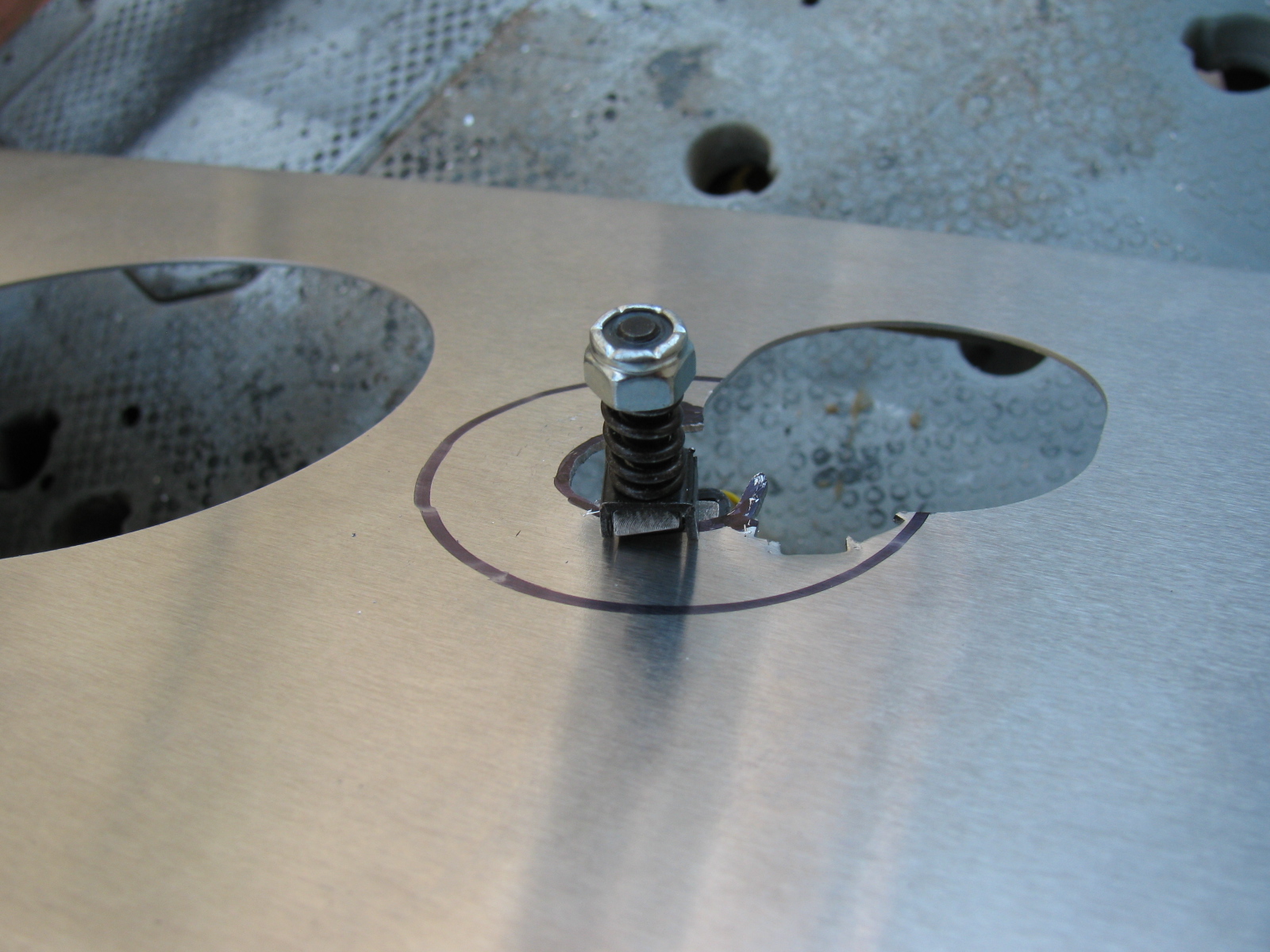
The lower mounts had a similar problem, but slightly worse, because there is no room for a wrench to tweak it. So, I used my new disc/belt sander to grind off about an eighth of an inch on each spacer. Because I wanted to make sure the ends remained square, I made a “sled” to hold the spacer and gauge the amount of material being removed. This 2-1/2 inch nut and bolt does three things: First, it safely keeps my fingers away from the sanding disc while holding the little spacer. Second, the side of the hex nut and bolt helps to ensure the spacer is 90 degrees to keep the end square. Thirdly, by screwing the nut so that the end of the bolt is the needed 1/8th of an inch inside the spacer, I can tell when to stop grinding: Sparks will start to fly when the bolt hits the sanding disc. (Something I remembered in 7th grade metal shop class – sparks can be an indicator of the type of metal – ferrous vs non-ferrous. How cool is that!)


Anyway – at the end of the day – Front suspension at 90 percent complete. Still need to attach those back-ordered steering arms and then attach the hubs.
I will start the rear suspension system next. . . .
Just before dinner tonight, I went to check my mailbox. But I stopped when I saw a white box with Factory Five Racing logo on it.
The FedEx man arrived at my house in stealth mode today. I was studying and although I heard a diesel truck stop, I did not hear a box land just outside of my gate.

This is the first box of stuff for my Type 65 Coupe
I received the manufacturer’s certificate of origin (MCOO), the nameplate with my serial number, a set of four rear taillights and a pair of upper control arms for the front suspension.


Ahhhhhh, the smell of new car parts is great!
Building Serial Number 586 begins soon.