Archive for the ‘wheel hubs’ Tag
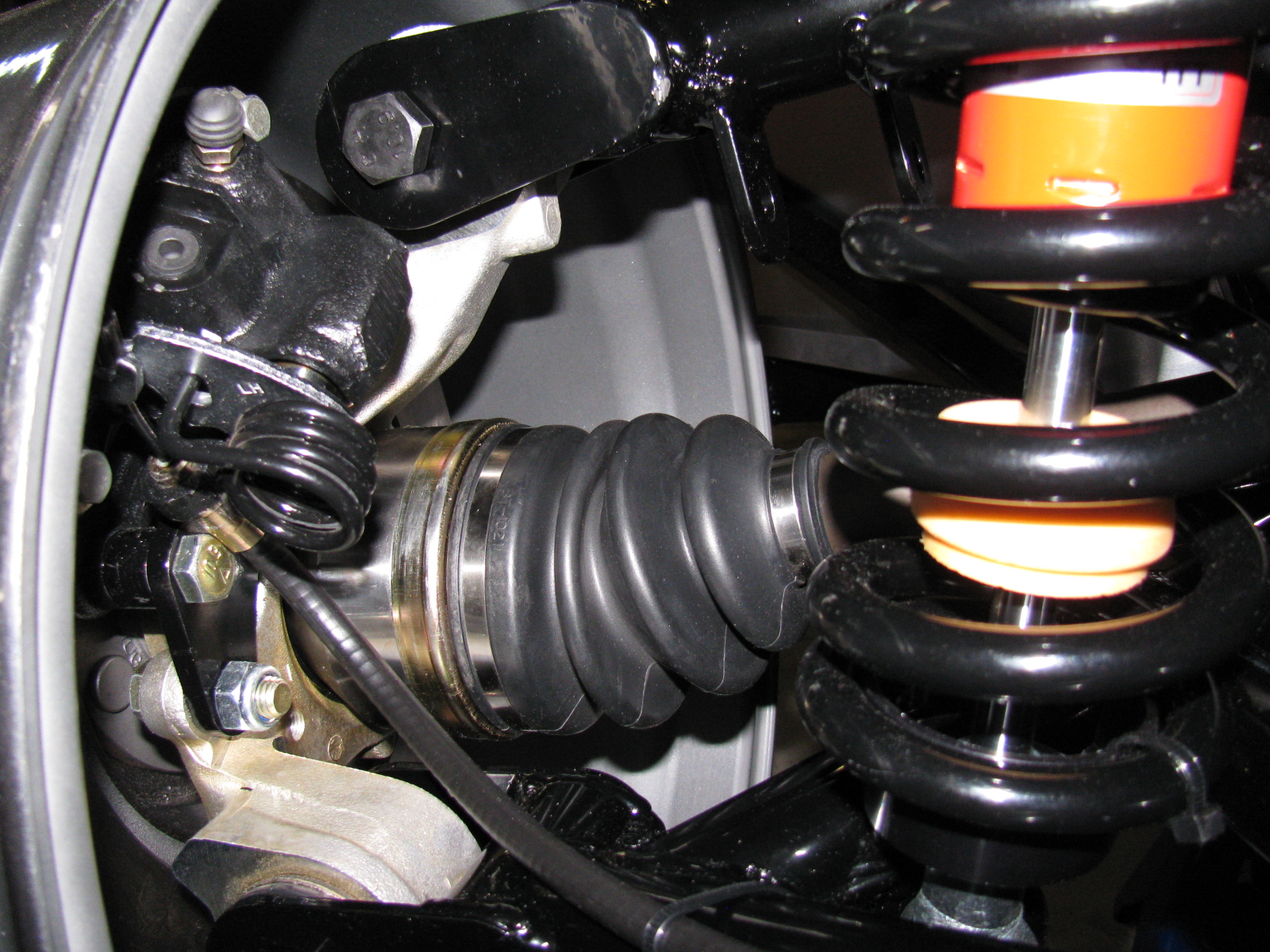
I forgot to add notes and images from the IRS (standard width) brake installation. Here are some images, plus a link to a YouTube video…


As you can see in the picture above left, an open end wrench can go onto the caliper mounting bolt. This was a button head Allen screw in the past. The emergency brake cable seems very tight and has a sharp bend, but this seems to work OK.


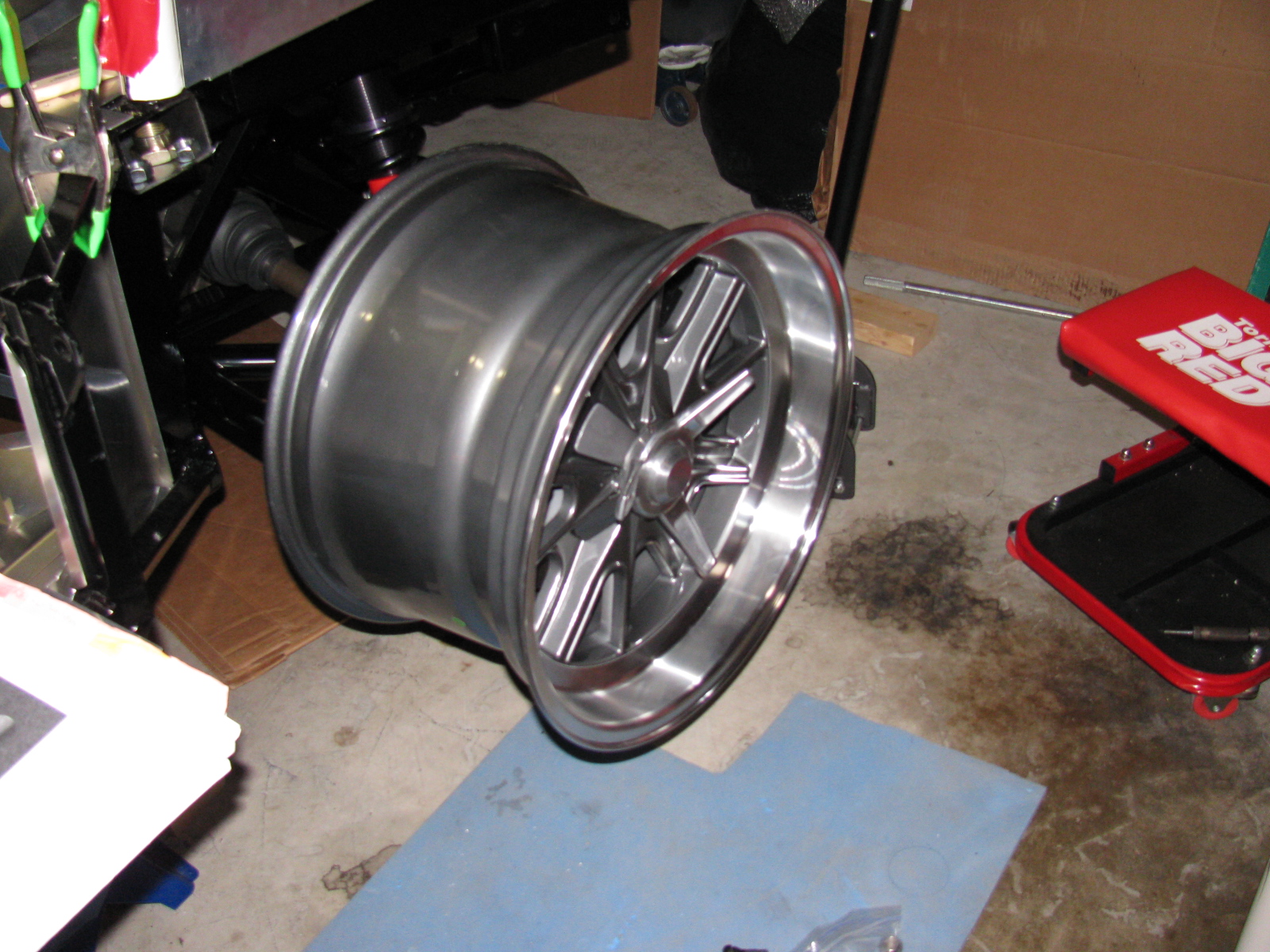
The vintage Halibrand replica wheels fit nicely over the axle-hub-brake assembly, but I don’t have tires yet.

The rear wheels are 17-inches by 10.5-inches, and the tires will be 275 / 40ZR17, probably BF Goodrich g-Force Sport Comp 2, but not sure yet.
A Silent Movie: Rear Brake Installation
Oh – almost forgot. Here is a silent movie about the rear brake installation:
http://www.youtube.com/watch?v=bVcX8-Nnqfo
It’s been cold in the garage lately (50s-60s), but I wanted to get some more work done on the Coupe. My 302 is scheduled to arrive this month, but I have a lot of work to do before I can install the engine and transmission. This is one of those rare times when I can tell a supplier to take their time.
Back to this weekend’s update: What’s cookin’. When I lived in a small townhouse, I used to make a lot of meals in a Crock Pot, and noticed a few things: First, it was very handy to fill the thing up with various meats and vegetables, turn it on, go away for a few hours and dinner would be ready. Second, the smell was always wonderful. And third, it actually made the house a little warmer.
I decided this third effect of Crock Pot cooking deserved a try in my garage – and it worked. In the morning, I filled the Pot with my universal minestrone recipe and added some leftover spare ribs from the freezer. I call it “Spare Rib Minestrone.” The recipe appears at the end of this entry. It is roughly based on a minestrone recipe from Fat Free, Flavor Full: Dr. Gabe Mirkin’s Guide to Losing Weight & Living Longer. And it is pretty tasty. It made the garage a few degrees warmer, too. Here’s a picture. . .

Cooking in the garage – a tasty alternative garage heating method!
Halibrand-Style Wheels Arrived
The Factory Five Racing Halibrand-style wheels are BIG and beautiful. Wheels are 17 x 9 in front and 17 x 10.5 in the rear, and feature a spin-off hub. I am still not completely sure what tires will go on these rims, my preliminary choice is a set of Goodrich Sport-Comp 2 or something like that. This may change as I get a little farther along on my build.


The Steering Rack
I decided to see if I could finish the front end this weekend, especially since a lot of the back-ordered items arrived – I finally have a complete set of parts for my complete kit!
The steering rack is a non-powered unit made for the Mustang. Like many others, the mounting ears were too close together and I had to spread them out by a little over a quarter of an inch. I tried to use my pipe wrench trick, but the tabs are a little small and I wasn’t able to exert enough torque to move them. Doing some research on the Factory Five forums, I kept reading about people using a nut and bolt to spread mounting tabs wider. I finally found a post that included a picture of this, for future reference, it is located here, and I am posting photos and captions on my site as well so it may be easier to find. It’s a pretty neat trick, although no one says anything about the mounting tabs springing or bending back into their original position – you have to “over-bend” the tabs in order to make the part fit.
Here is my version of the mounting tab spreader tool using threaded rod, washers and nuts – I used 1/2-inch all-thread, since the 3/8-inch rod seemed a bit flimsy:

This really didn’t work too well, the tool needs another nut to hold it securely.

Like this

In the photo above, the open end wrench is being used to spread the mounting tabs outward. If the mounting tabs need to be smaller/tighter, move the washer and nut to the outside of the tab, and tighten the nut – squeezing the tabs closer together.
For the steering rack, I ran into another problem – that turned out to be a non-problem. As you can see here, after spreading the tabs out, the rack fits between the ears – but the holes on the passenger-side need to be moved about an eighth or a quarter of an inch to the left. After thinking about how long this will take using a rattail file, I took a break and thought about the steering rack. The driver’s side mounting tabs had a slot on one side – how come I am not able to move the rack over towards the driver side of the chassis?
The answer is, of course, yes, the slot is just enough to make the rack fit nicely. I used a punch and a mallet to move the rack into position. Success!

Compare the hole on the left (I used silver marker to show where to enlarge the hole) and the slot on the right. No reaming needed – I used a punch and a mallet to move the steering rack into place.
So now the tie rod ends have to be connected to the steering arms. But here is another problem – the driver side tie rod is too long – can I just get a hacksaw and cut off about an inch, as shown by the blue tape?

The driver side steering rack tie rod seems too long – but wait – something is amiss. ..
I decided to stop the steering rack installation at this point and get some answers before cutting the tie rod – because, as Norm Abram always said, “Measure twice, cut once.”
I came across the Summit Racing – Factory Five Racing Roadster build today – and there is a nice picture of the steering rack-tie rod connection posted here – this is for a Roadster, but I think the Coupe shares the same configuration. I have to give F5R a call to verify something – in the Roadster build, the steering tie rod to steering arms are upside down compared to my “dry fit” – Do the Coupe tie rods mount the same way? Also, the Summit Racing car has two lock nuts for each tie rod – my kit came with one lock nut for each side. The manual does not show the ends of the steering rack – poor photo-cropping.
Getting the Shaft
I did some test-fitting of the steering shaft – after some head-scratching moments, I figured out that I needed to remove the adapter that came with the lower end of the steering shaft, and replace it with another one, from another box of stuff. The length is just right, I have seen some early posts about the steering shaft being too long.
But I ran into another problem – the shaft does not come through the dashboard in the correct position. It is not as bad as some others I have seen, but still is quite a ways off. I am not sure if I can just cut the dashboard hole bigger to allow the shaft to come through, and patch the spaces or – what. More fiddling is needed.
Floor and Footbox Fitting – Passenger Side
I decided to do some more sheet aluminum work – this time, fitting the passenger side floor and footbox. Using the same technique as the trunk floor, I cut the passenger floor into three pieces. After the cutting, I noticed that I could have done this with only one cut, but the three pieces will be OK. I kept the left side un-cut, since it may be seen when the car is done. (I am not sure if I will apply paint or put carpet on the transmission tunnel area yet.)
At this point, everything is being held in place with Cleco pins. I want to test-fit, trim, drill and de-burr all the aluminum panels first, then apply paint – or powder coat them.
So although I think I did a lot of work on the Coupe this weekend, a lot of it does not seem to show. It still does not look like a car yet.

Cutting the passenger side floor.

Passenger side footbox – another jigsaw puzzle!
Something is Making Me Go – “Hmmmmmmm”
I noticed and wonder why the passenger-side side body mount area sheet aluminum is different from the driver-side side body mount area aluminum – take a look:

Driver side – side body mount near the footbox. . .

Passenger side – side body mount area, near the footbox – see the difference?
Here’s another look:

Driver’s side

Passenger’s side. . .
This is making me go, Hmmm. Or more like Arrrrrg.
Season’s Greetings
Somewhere during the weekend, I installed my Christmas lights. I decided to cut back this year, because of all the work I am doing on the car. My “Ho Controller” and box of new lights and other parts I bought last year will have to wait until next year. In the meantime, here is a shot of my display. One of my Universal Rules for events is: “Everything you setup must be taken down and put away.” So many people spend hours and days – or even longer – putting up such decorations. My setup: less than 10 minutes to deploy, and even faster to take down!

Before I forget – here is the Spare Rib Minestrone recipe:
Spare Rib Minestrone
Yield: 6 servings
1 Large onion, chopped
5 cloves garlic, smashed
2 celery stalks, diced
2 cups of chicken stock
1 28 oz can of crushed tomatoes
1 tsp oregano
1 tsp basil
1 can pinto beans
1tsp red pepper flakes
6 small red potatoes, diced
1 large zucchini squash
Some leftover spare ribs, with BBQ sauce
Put everything into the Crock Pot, with the leftover ribs on top, surrounded by the vegetables. Put the Pot on High for about 6 hours or until the vegetables are tender. Based on the Primo Minestrone recipe by Dr. Gabe Mirkin, MD in Fat Free, Flavor Full
The front steering arms came in the day before Thanksgiving. That meant that I could continue building the front suspension. These little cast iron parts were the things holding my progress:

I installed the steering arms without too much drama. Installing the front hubs onto the spindles was another matter. The instruction manual says something about them being a tight fit, and that is true. I did not want to damage anything, so I used a PVC pipe elbow (remember the body dolly? This was a left-over part from that…) to protect the hub, and I used a plastic hammer to pound the hub into place. A few whacks and it slid right in. I hope that I won’t have to remove them someday – they are stuck on really tight.

And yes, a coupler or a T would have made a better anvil, but all I had on-hand was this elbow. Anyway – the hubs are now mounted to the spindles.

Torque spec for the hubs is 225 to 250 lbs/ft. This is a lot. The nut takes a 36mm socket and I bought one earlier (Coin Star money) just for this step. It took a lot of cranking on my 1/2-inch torque wrench to meet that 250 lb mark. I thought I was going to lift the chassis off the jack stands!
Thanksgiving Ribs
Meanwhile, I prepared some Kansas City Style pork spare ribs for Thanksgiving dinner at my sister’s house. I was in a hurry, and forgot to completely trim the ribs (the cartilaginous tips). I did, however, remember to remove the pleura – the silver skin on the back of the ribs.
If you don’t know about removing the skin from spare ribs, then I am sure you may have experienced eating that stuff somewhere. The pleura is the tough membrane that you might see on the back of the ribs. If left on, it blocks the spices and will never get soft after cooking – it is sort of like chewing gum, and ruins the eating experience….
Anyway, they were still very tasty, although I was out of paprika. No one else noticed it missing – but I sure did.

Ribs with a dry rub. I made two racks for Thanksgiving this year.

Smoky goodness.
After Thanksgiving Turkey
Per my tradition, the day after Thanksgiving, I went to the local grocery store and found a good deal on a fresh 12-lb turkey. I decided to try a recipe from Steven Raichlen’s Primal Grill TV show – see Orange Brined Turkey.
Strangely, both the book and the website say this is for turkey breasts. On the DVD, Steven smokes a whole 12-lb turkey. At any rate, I salivated over this since last year, and finally got to try it. Take a look at my version The bird is a hen, just over 12 pounds . . .

Orange brine for the turkey.

I need a bigger bucket or something for brining the turkey. I turned her (it’s a hen) over in the middle of the night.
Back to Work on the Coupe
Since the turkey had to soak over-night, I went back to the Coupe project. I started to assemble the front disc brakes, when another delay came along: No “supplied grease” for the disc brake slider pins. So I went onto the Factory Five forums and searched on what sort of special grease this might be. I almost skipped this step, but I am glad I did not. Lots of bad things can happen if the brake calipers stopped sliding on the slider pins.
Turns out the grease is special – the grease must be silicone-based, high temperature and must not affect rubber. So I did some more research and found this stuff: Permatex Ultra Disc Brake Caliper Lube Silicone Formula Item #24115. High temperature, silicone based and intended for brake caliper use.
There are some little spring clips that go into the brake housing, and some rubber boots that fit onto the caliper slider pins. The pictures are not too clear and I had to do some fiddling with the parts to make things look right. Here are some pictures that may help other builders. . .

This is the clip that goes into the long slot in the middle of the housing. If you are struggling to get it in, it is probably backwards. Hold it like this and insert it into the housing from the inside. It will just pop into place with a little bit of pressure.

The caliper slider pin boot is easier to install if you “un-curl” it first, like this.

Then you can push the little lip into the shallow groove in the pin. . .

. . . to make it look like this.
Since I was at the car parts store, I also bought a box of disposable gloves and some adhesive for the aluminum panels. There’s a ton of postings on what adhesive to use on the Factory Five Racing car projects. Many different adhesives are mentioned. But there was one build gallery that I found, and I am going to use the product they used – it is Permatex Ultra Black RTV silicone gasket maker, Item #24105. This is what Kirkham Motorsports uses in their projects, so I figure it would be acceptable in my Coupe build. Kirkham has an online assembly manual posted, it basically follows David Kirkham building one of his cars: Kirkham Motorsports Assembly Manual.
What Good is a Sale on Something When It’s Out of Stock?
Since I was running about getting the grease and other stuff, I decided to go tool shopping. A local hardware store chain had a 50 percent off sale on Makita and Milwaukee power tools this weekend – I thought this was the perfect time to go get that right angle drill I wanted. I got to the store, only to find no Makita or Milwaukee right angle drills available. I went to two stores and wasted half of my day looking for the thing. I decided to look for an alternative to the right angle drill – how about a right angle drive attachment? I did not find one of those, either. So I left the hardware store empty-handed – I think this was the first time that ever happened!
Back to the Turkey
After an overnight soak, the turkey is ready for the smoker.

Getting the Big Green Egg up to temperature (250 degrees F). Hickory chips were added.


I can never resist peeking. Orange brined turkey, after the first hour.

After the 2nd hour. I rubbed the turkey with butter and continued to smoke.

After 4 hours. Almost done.

Total time in the smoker: About 5 hours. Temperature in the thigh 170 degrees F. After a 15 minute rest, time to carve!


Yes, this is as tender and juicy as it looks. The mayo-mustard-triple sec dressing that is part of this recipe is very good. I think I will try this with lemons next time.
So not much work completed on the Coupe today, but the holiday weekend is not quite over. I hope to complete the front end tomorrow.
I’ve been busy with work and other chores so haven’t had much time to work on the car and update these pages – but – here is a re-cap of the work done over the last few sessions.
The day after the Welcome BBQ, I built a PVC pipe dolly for the Coupe body. It is made of 1-1/2 inch PVC pipe, some Ts, some 90 degree elbows and some casters from the “As-Is” bin at the local Ikea furniture store. I chose the plastic pipe because I had some connectors and lengths of pipe leftover from some other project. If I were to do this over, I would have made the dolly with 2 x 4s.


Next, I removed all the sheet aluminum from the chassis, marking the outlines of chassis tubes underneath. This is done to indicate where to drill holes for the pop rivets that are used to mount the sheet material on the finished car. This went pretty smoothly – except for the trunk area. It reminded me of one of those mechanical puzzles – you have to warp the trunk floor upwards and then slide and pull it toward the front of the car and then through the roof section. Or something like that. It is a tapered shape. After scratching the area just behind the seats – where the roll bar attaches – I decided there had to be a better way to get the trunk floor in and out of the chassis – this would be more important later in the build, because I will paint the trunk area. I decided to cut the trunk floor in half length-wise. Later, I found some posts in the forums that mentioned this, so I kind of re-invented the wheel on this one.
I used my power jig saw and a fresh metal cutting blade for this. My long saw guide was in another garage, so I had to come up with an alternative straight edge – a really long power strip worked fine. I centered a line on the trunk floor, and made the cut. You can see the wax along the cut line, this lubricates the blade and helps prevent the aluminum from clogging the blade.


The independent front suspension (IFS) came next. The steering arms are on back-order, but I decided to start building this section. The parts are beautiful, nicely powder-coated black. Some parts have a neat little detail built into them – see the “5” on the front lower control arm? Sort of like the hardware version of an “Easter Egg,” if you know what I mean.

I ran into a small snag at this stage. The mounting points on the body for the lower control arm were slightly off. I solved this by squeezing the arm into place with a quick-clamp. Easy.

A similar, but more difficult puzzle for the upper and lower shock mounts. A pair of aluminum spacers is used to center the coil/shock assembly on their mounts – the spacers were too long. This is a common problem, and it is documented on the forums. There are several ways to correct this, and I combined several hints to solve my issue. First, the upper mounts were a total of one-quarter of an inch too tight. I padded the rear-facing mounting ear with a rag, grabbed it with a pipe wrench, and pulled. It was surprisingly easy to bend that mounting ear to make it fit.
The lower mounts had a similar problem, but slightly worse, because there is no room for a wrench to tweak it. So, I used my new disc/belt sander to grind off about an eighth of an inch on each spacer. Because I wanted to make sure the ends remained square, I made a “sled” to hold the spacer and gauge the amount of material being removed. This 2-1/2 inch nut and bolt does three things: First, it safely keeps my fingers away from the sanding disc while holding the little spacer. Second, the side of the hex nut and bolt helps to ensure the spacer is 90 degrees to keep the end square. Thirdly, by screwing the nut so that the end of the bolt is the needed 1/8th of an inch inside the spacer, I can tell when to stop grinding: Sparks will start to fly when the bolt hits the sanding disc. (Something I remembered in 7th grade metal shop class – sparks can be an indicator of the type of metal – ferrous vs non-ferrous. How cool is that!)


Anyway – at the end of the day – Front suspension at 90 percent complete. Still need to attach those back-ordered steering arms and then attach the hubs.
I will start the rear suspension system next. . . .