
After several weeks, it is good to get back to work on the Factory Five Racing Type 65 Coupe. I finally completed drilling the rivet holes for all cockpit aluminum panels, and added a battery cut-off switch as you can see above.
Here is a hint for builders – there is a fairly large gap in the bottom right corner of the driver’s side floor and the “A” shaped piece that meets the transmission tunnel. I looked at several Coupes and Roadsters and they all have this space. However, by pushing on the A-shaped piece from behind (under the chassis and in the engine bay) – this gap can be closed up nicely. See below. . .
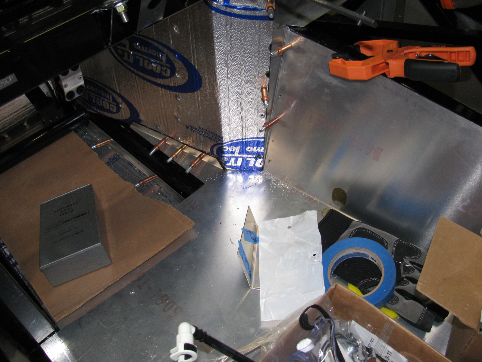

But what about this area, at the rear of the driver’s side door – indicated by a piece of blue masking tape – see that gap? Does something cover this space up or do I need to fabricate a replacement panel? Both sides look the same.

As mentioned in a previous post, I finally decided to mount the external fuel pump under the Factory Five Metal battery box. This is a protected location and is a low point on the chassis.

One problem will be access to the fill and drain holes for the Ford Racing differential. I had to drill out the rivets previously installed and tapped some 1/4-20 holes – this will enable the removal of the battery box when draining and filling the rear end fluid. Not the ideal situation, but I do not see too many alternatives to this arrangement.
My Ford 302 V8 has an MSD Atomic electronic fuel injection system, and I am running both feed and return fuel lines. Here is a picture of the tank end. . .

The fuel line runs from the first filter (right side of the chassis) to the fuel pump, and goes around to the driver side. Then it goes under the rear end to the passenger side of the chassis, where it goes to a second fuel filter mounted under the passenger seat, and finally to the engine.
The same path will be used for the return system. Pretty much standard layout.
Next Build Session
Depending on the weather, I will remove all interior panels and paint the under side with automotive under body paint. It is a rubberized black paint which should deaden some road noise, insulate heat and protect the panels from road debris.
Another item on the next to do list is the wiring harness. Here is a look at the main portion. . .


Leave a comment