Archive for the ‘sheet aluminum’ Tag
I planned on doing more front end work this past weekend, including the installation of the steering rack, since I keep kicking that awkwardly long box on the garage floor. Then I wanted to move to the rear suspension, since the CV axles are finally on the way.
But as I thought about doing the work on the rear end, I decided to start drilling and fitting the rear trunk aluminum sheets. I wanted to avoid dropping aluminum and steel debris onto the new suspension and drivetrain components.
I want to drill and fit, not fasten and mount these panels, because they will be painted or powder coated later. This is always a messy and time-consuming task, and in the Coupe, a lot of the panels will be visible. Someone on one of the Factory Five forums said that if you count the number of holes you have to drill, you will lose the will to live. Funny. And true. Here are some pictures of the trunk aluminum.

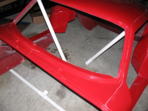
Over all view of the Coupe trunk area. I used lots of Clecos on the back seam, because I had to pull the aluminum sheet on the rear panel tight against the floor.

The blue tape in this area is for a removable hatch to enable access for rear tail lights and the wiring harness. Better do that modification now, rather than later. Other access panels and storage boxes will be installed at various locations in the floor and the sides of the trunk.
I should draft a construction plan for this project, since I am almost randomly moving through the assembly manual.
My vintage-style Halibrand wheels still have not arrived, and I am missing some brake system fittings. When those parts arrive, I will have all the ingredients for the Factory Five Racing Type 65 Coupe Complete Kit. The engine and transmission should be done soon, delivery is sometime this month.
Having things from Factory Five on back order is not so bad. It just means that packages arrive every now and then, and it is sort of like having gifts to open and see. For example, earlier this week, the box containing the exhaust headers and rear view mirror finally came back to me. In addition, I received the rear brake kit and the rest of the rear end hardware and fasteners.
The headers are nicely polished aluminum and are surprisingly light for their size. It looks like they mount to the exhaust muffler assembly with these splice-connector sections. Other versions of this exhaust are joined with a flange arrangement. I am not sure if I like this method of connecting the headers to the muffler assembly. I will have to post a question on the Factory Five Forum to see what others have done.


The steering arms are still missing (FedEx tracking info indicates they are in transit and will arrive just before Thanksgiving – this is great timing, since I will have a few days off to do some more work on the car), so I cannot install the front disc brakes. The CV shafts are missing so although I can start on the rear end, I will have to stop in the middle and wait for those pieces before I complete the rear end assembly.
So, I decided to work on the aluminum panels this weekend. I marked, center-punched and drilled the driver’s side footbox first. I used my new cleco pins and pliers for this sheet metal project. I really like them – I wish we used these in Mr. Spence’s 7th grade metal shop class!


See the gap at the peak of the box? I will install a strip of thin bar stock over the entire top seam to make it look better.
Some of you are wondering – what’s a cleco? I wondered about that, too. Wikipedia says, “A cleko, also spelled cleco, is a fastener developed by the Cleveland Pneumatic Tool Company. . .”
http://en.wikipedia.org/wiki/Cleko
So the next thing you may be wondering is – why do I have to use temporary fasteners to put these sections together? Another good question. I have to trim, drill and assemble all of the sheet aluminum parts – and then take everything apart so I can de-burr the holes, remove all the marks and scuff the panels to get them ready for paint. Although some builders have left these panels un-coated and raw, I decided to apply a finish to all the panels to prevent corrosion. My plan is to paint all interior panels (except the dashboard) with silver Rust-Oleum high temperature barbecue paint. I will paint the dashboard with Gray Hammertone – a darker color than silver, and it will have a nice contrast against my AutoMeter gauges.
Everyone seems to talk about the high temperature part of this paint, but no one mentions the fact that no primer is needed. I think that is one of the best features of this paint – one less step to do.
An alternative to the BBQ paint is what I use for my electronic chassis project boxes – Rust-Oleum Appliance Epoxy. This is another paint that does not require a primer, and the stuff is pretty durable. I would use that instead, but the colors are limited to white, black and almond. Yuk. Too bad.
At least, that is the plan so far. I might change. I am also considering some color alternatives to my original plan of having a white body and black stripes. But that part is a long way off. I will make a final color selection when the Halibrand wheels arrive – they still have not shown up yet.
It looks like there are just three things missing from the kit: The front steering arms, the rear CV shafts and the Halibrand wheels. The 302 V8 and T5z transmission should be here in December – so some serious building is about to begin!
I’ve been busy with work and other chores so haven’t had much time to work on the car and update these pages – but – here is a re-cap of the work done over the last few sessions.
The day after the Welcome BBQ, I built a PVC pipe dolly for the Coupe body. It is made of 1-1/2 inch PVC pipe, some Ts, some 90 degree elbows and some casters from the “As-Is” bin at the local Ikea furniture store. I chose the plastic pipe because I had some connectors and lengths of pipe leftover from some other project. If I were to do this over, I would have made the dolly with 2 x 4s.


Next, I removed all the sheet aluminum from the chassis, marking the outlines of chassis tubes underneath. This is done to indicate where to drill holes for the pop rivets that are used to mount the sheet material on the finished car. This went pretty smoothly – except for the trunk area. It reminded me of one of those mechanical puzzles – you have to warp the trunk floor upwards and then slide and pull it toward the front of the car and then through the roof section. Or something like that. It is a tapered shape. After scratching the area just behind the seats – where the roll bar attaches – I decided there had to be a better way to get the trunk floor in and out of the chassis – this would be more important later in the build, because I will paint the trunk area. I decided to cut the trunk floor in half length-wise. Later, I found some posts in the forums that mentioned this, so I kind of re-invented the wheel on this one.
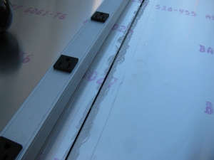
I used my power jig saw and a fresh metal cutting blade for this. My long saw guide was in another garage, so I had to come up with an alternative straight edge – a really long power strip worked fine. I centered a line on the trunk floor, and made the cut. You can see the wax along the cut line, this lubricates the blade and helps prevent the aluminum from clogging the blade.


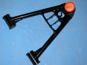
The independent front suspension (IFS) came next. The steering arms are on back-order, but I decided to start building this section. The parts are beautiful, nicely powder-coated black. Some parts have a neat little detail built into them – see the “5” on the front lower control arm? Sort of like the hardware version of an “Easter Egg,” if you know what I mean.

I ran into a small snag at this stage. The mounting points on the body for the lower control arm were slightly off. I solved this by squeezing the arm into place with a quick-clamp. Easy.

A similar, but more difficult puzzle for the upper and lower shock mounts. A pair of aluminum spacers is used to center the coil/shock assembly on their mounts – the spacers were too long. This is a common problem, and it is documented on the forums. There are several ways to correct this, and I combined several hints to solve my issue. First, the upper mounts were a total of one-quarter of an inch too tight. I padded the rear-facing mounting ear with a rag, grabbed it with a pipe wrench, and pulled. It was surprisingly easy to bend that mounting ear to make it fit.
The lower mounts had a similar problem, but slightly worse, because there is no room for a wrench to tweak it. So, I used my new disc/belt sander to grind off about an eighth of an inch on each spacer. Because I wanted to make sure the ends remained square, I made a “sled” to hold the spacer and gauge the amount of material being removed. This 2-1/2 inch nut and bolt does three things: First, it safely keeps my fingers away from the sanding disc while holding the little spacer. Second, the side of the hex nut and bolt helps to ensure the spacer is 90 degrees to keep the end square. Thirdly, by screwing the nut so that the end of the bolt is the needed 1/8th of an inch inside the spacer, I can tell when to stop grinding: Sparks will start to fly when the bolt hits the sanding disc. (Something I remembered in 7th grade metal shop class – sparks can be an indicator of the type of metal – ferrous vs non-ferrous. How cool is that!)


Anyway – at the end of the day – Front suspension at 90 percent complete. Still need to attach those back-ordered steering arms and then attach the hubs.
I will start the rear suspension system next. . . .


