On Saturday morning, I remembered that I stopped working on the sheet aluminum. So I decided I should get that Cleco-ed in place so I can get the panels ready for prep and paint. Then I can move on to the fuel tank, and then – finally – install the engine.
-

- Type 65 Coupe cockpit aluminum. A big jigsaw puzzle. But you get to trim pieces to fit. All the sheet aluminum will be fitted and drilled and temporarily mounted with Clecos. Then every panel will be removed, de-burred, de-greased and prepared for painting. Then the panels will be permanently installed with rivets or screws and silicone adhesive.
-
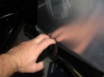
- This is disturbing. The square tubing behind the cockpit outer back wall has this gap – Is the panel supposed to rivet to this tube, or does it “float”? Or should I add some spacers or shims to fasten the panel tightly against this tube?
-
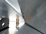
- The sheet aluminum fit is very tight, and seams must be very slightly trimmed. This is a view of the driver side rear corner. The bottom will be pulled tightly against the vertical surface when riveted.
-
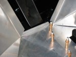
- Cockpit, passenger side, rear panel. I cut off the L-shaped tab from both sides of the large A-shaped piece that covers the rear end, and added a small piece of aluminum angle stock at the floor. This will enable an alternative order when fastening this piece with rivets.
-
- This gap on the driver side can be closed up by pushing on the A-shaped piece from the engine side. I may add an additional piece of angle aluminum at the bottom later.
-
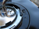
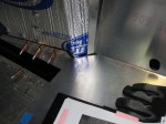
- Close-up of the fuel pickup lid. This is not pictured in the manual – this is how the lid should be locked into place on the tank. The little convex bump should securely mate against the concave indentation on the fuel tank. The gauge sender is mounted in the same way.

Leave a comment