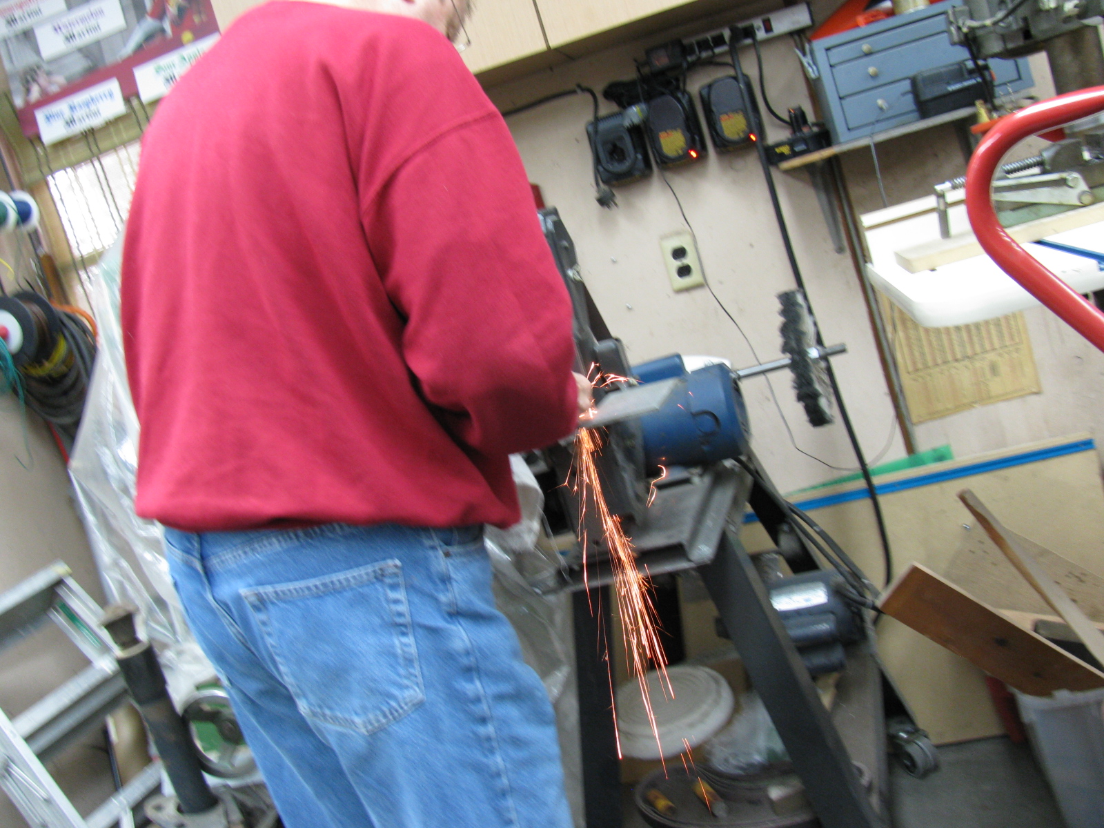
My go-to car builder friend Spider Larry once again came through for me. Using a Mapp gas torch and a piece of pipe, he separated the ball joint from the top mount for the passenger side suspension. Here are some pictures from the dis-assembly and re-assembly process on the Type 65 Coupe IFS, passenger side.

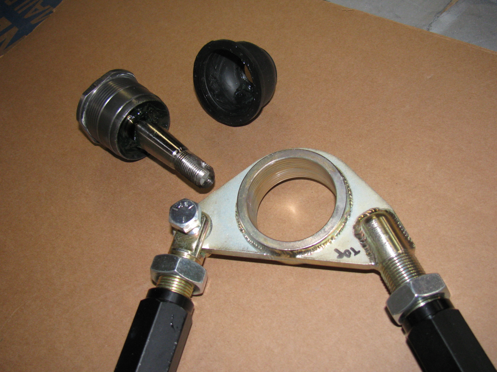
Here is the correct passenger side upper control arm and ball joint assembly:


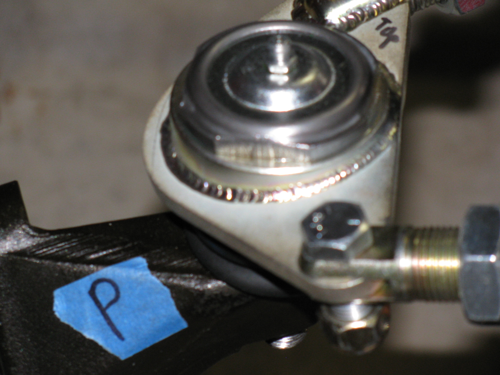
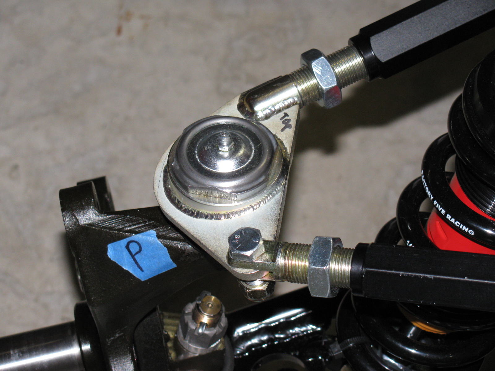
The driver side looks like this:


So you MUST ignore the manual when it says to create a “left and a right unit with the ‘solid corner’ pointing to the front of the car.”
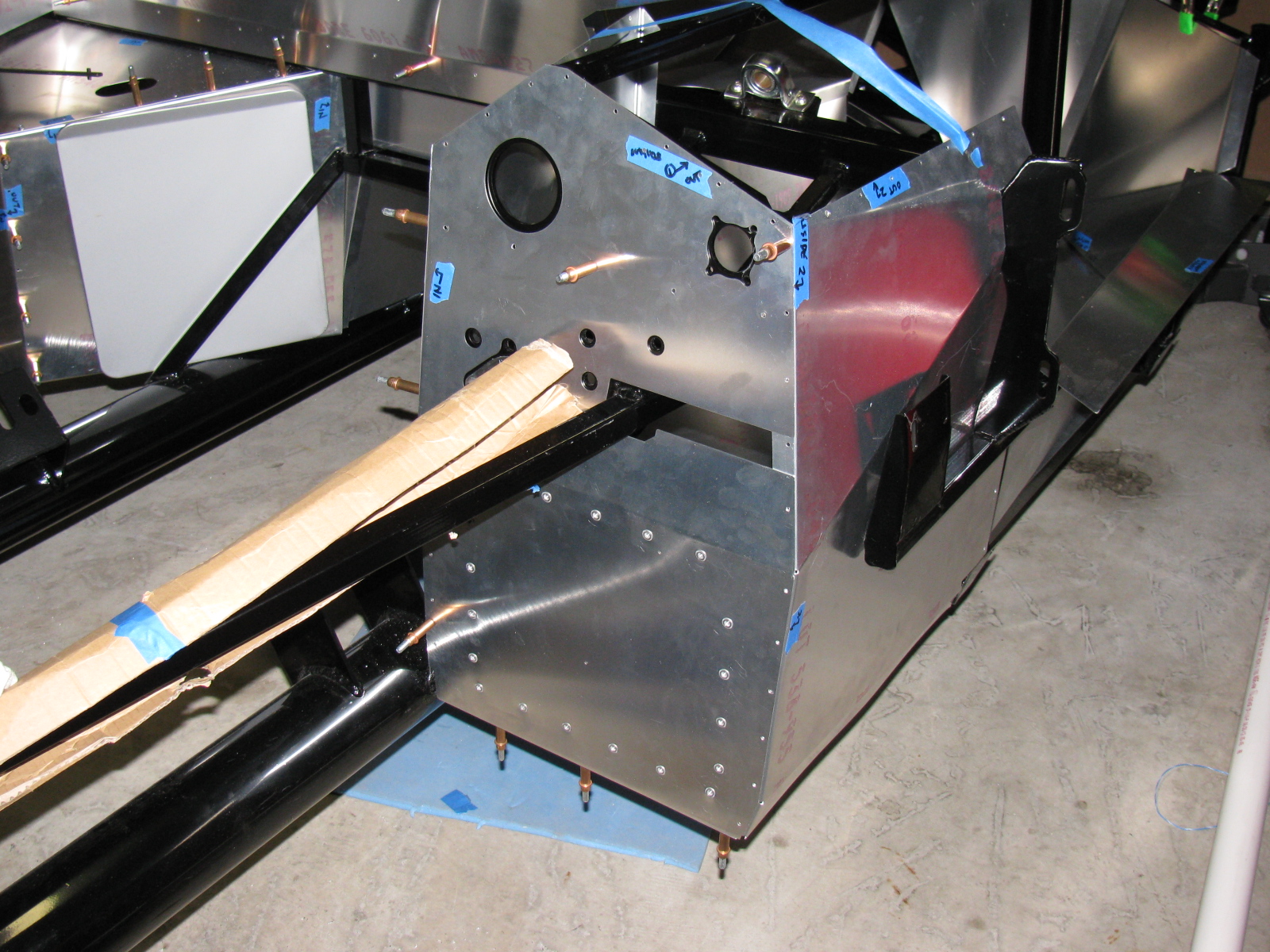
Footbox Heat Shields
I located, dry-fit, and drilled mounting holes for the driver and passenger footbox heatshields. The material is cookie sheet steel from the local grocery store. They have a nice rolled edge and will help deflect heat from the engine bay coming into the car interior. I am using riv-nuts and spacers to mount these sheets – er – heat shields to the footboxes.
I used BBQ paint for the shields, but may decide to powder coat the engine bay sheet metal parts, including the heat shields.
But I have to decide this quickly, since the engine is scheduled to be delivered within a few days!
Here’s the driver footbox with riv-nuts installed. All aluminum panels for the engine bay will be powder coated, the others will be painted.
Air Conditioning
Here is a picture of the air conditioner unit and where it will go. It fits behind the passenger side dashboard area, where a glovebox wold normally go. I need to allow space for the ducting and the windshield wiper mechanism, which mounts in the same area. A box to house the A/C unit will have to be fabricated.

The IRS – Independent Rear Suspension
Note to builders: This procedure is quite difficult, even with a helper or two. It is highly recommended to keep small children away to protect them from hearing rated-R and -X words and phrases loudly coming from the underside of the chassis and to keep them safe from thrown objects.
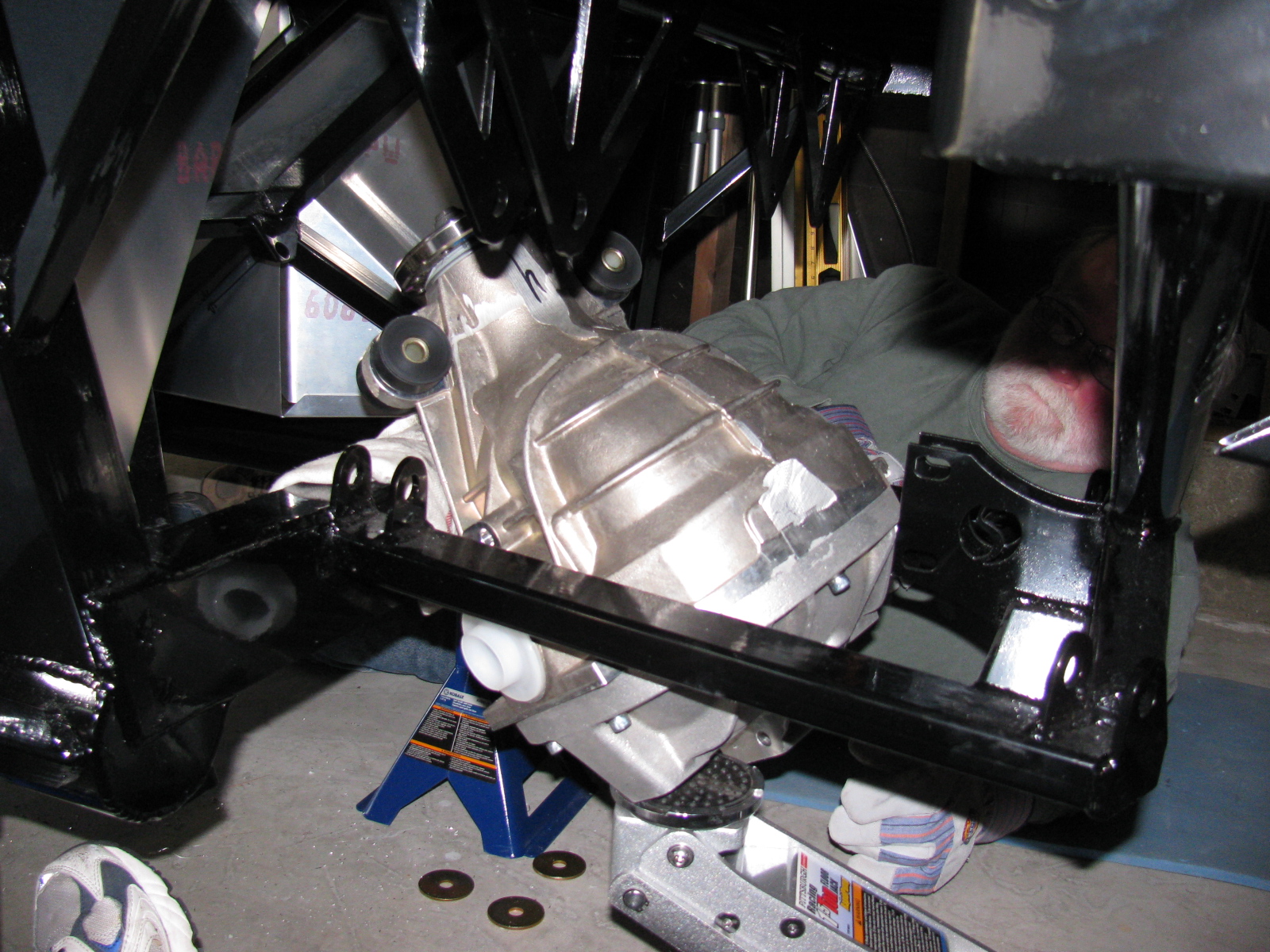
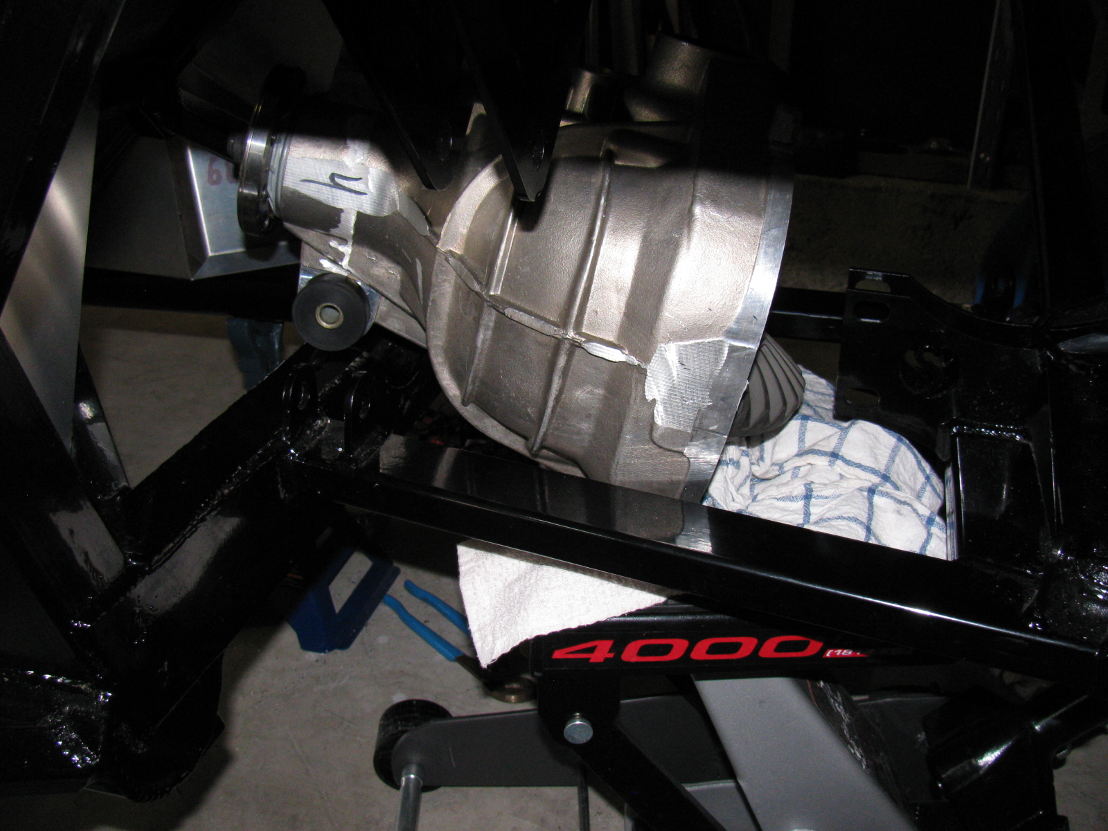
Since my ham radio friend Larry was going to stop by for a visit, I decided it would be a great time to get him to help me boost the rear differential (pumpkin) into the rear suspension cage. The Factory Five Racing assembly manual calls this unit the “IRS center section.”
There are many posts on how difficult this step is. The manual says, “It installs from the bottom with the driveshaft flange pointing straight up and the axle holes lined up front to back with the chassis.”
Err. So that means the giant 70 pound, lop-sided bowling ball like thing must be pushed up sideways, 90 degrees from the way it mounts onto the frame, and then must be twisted 90 degrees in the opposite direction to drop into place. This cannot be done safely with just one person. I found out that this is actually impossible to do with two people.
After several long hours and a phone call to Spider Larry, the pumpkin still refused to go into place.
I began to think about getting a grinder and removing any offending protrusions on the differential case and chassis to make this thing fit. My ham friend Larry had to leave, but a neighbor showed up, who also happened to be a car builder. I put Phil to work right away…
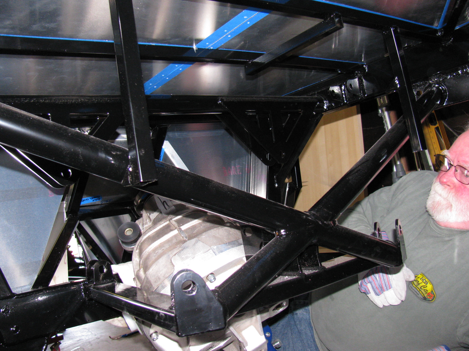
We tried a different route, maybe through the X-member at the rear of the chassis could work. So we used the jack to lift the differential high enough to check. We made a few measurements. No way.
We measured again, and noticed that no matter how you turn this pumpkin, it will not fit past the rear cover mounting plates.
We decided to remove the rear cover.
After unscrewing ten Allen bolts, and giving the rear cover a light tap with a rubber mallet, the cover popped off, very much like breaking an egg. To gain another inch of clearance, we removed the two plastic dust caps from the axle holes. Verifying that the diff does NOT have to come apart to mount the rear brakes, we put it back on the jack. Modifying the instructions, we lifted it with the driveshaft flange pointing up and the axle holes at a 45 degree (not 90 degree) angle, and pumped the jack. Now it went past the offending rear mounting plates, and into place.
Of course, now the differential must be re-sealed, so we tried a dry run with the rear cover. Yes, this will work. I currently have the pumpkin suspended above the mounting location, held in place with the jack, a 2×4, and a nylon strap. I will finish mounting this beast at the next build session.
Here are lots of pictures of the wrong way to do this. A video of this procedure would be most helpful, but I am sure most builders will have enough in their hands to not have a camera operator getting in the way.


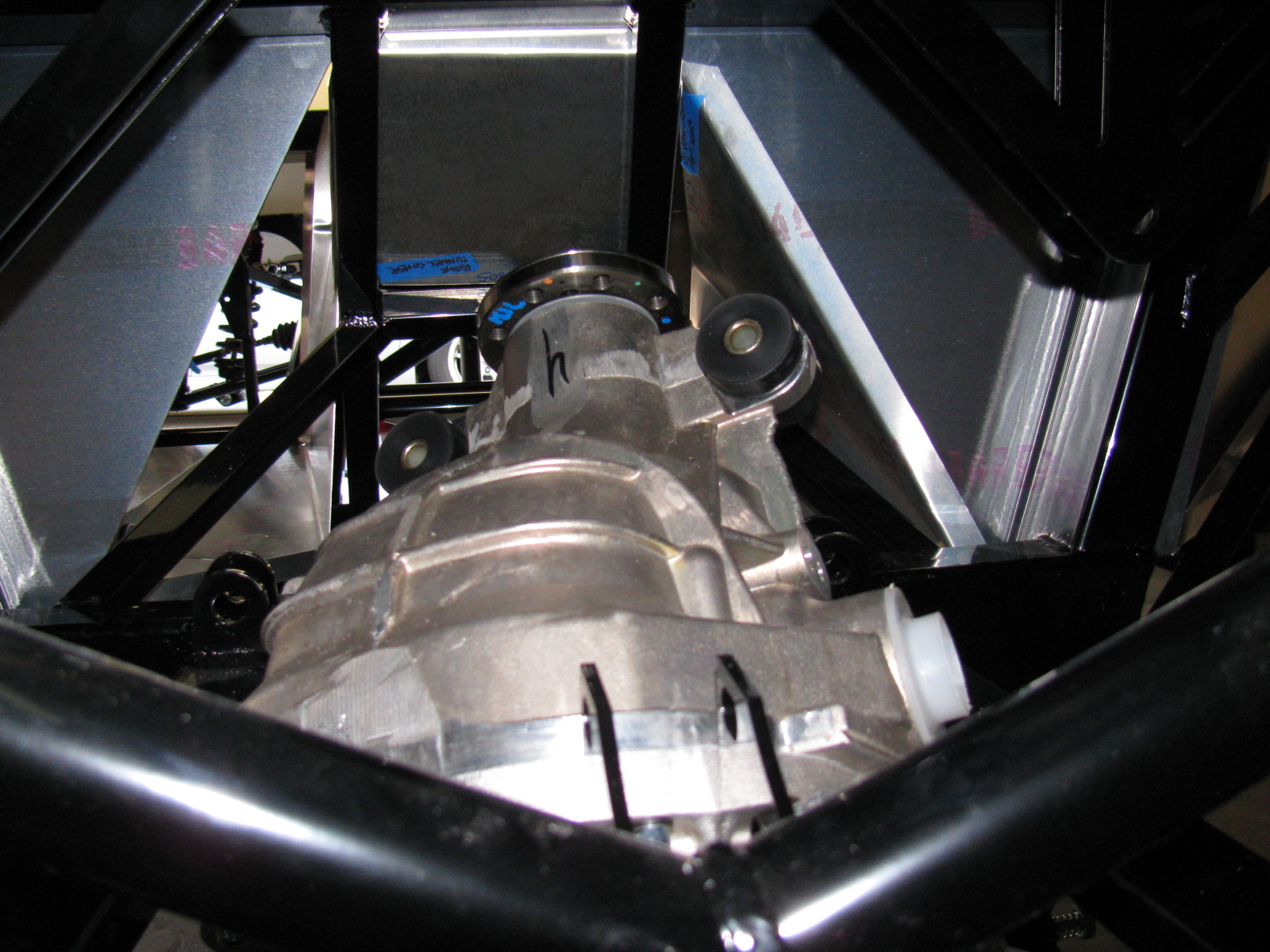


So – take my advice, save at least 6 hours and lots of non-child-approved words and thrown objects, and remove the differential rear cover before you install your IRS center section. . . .


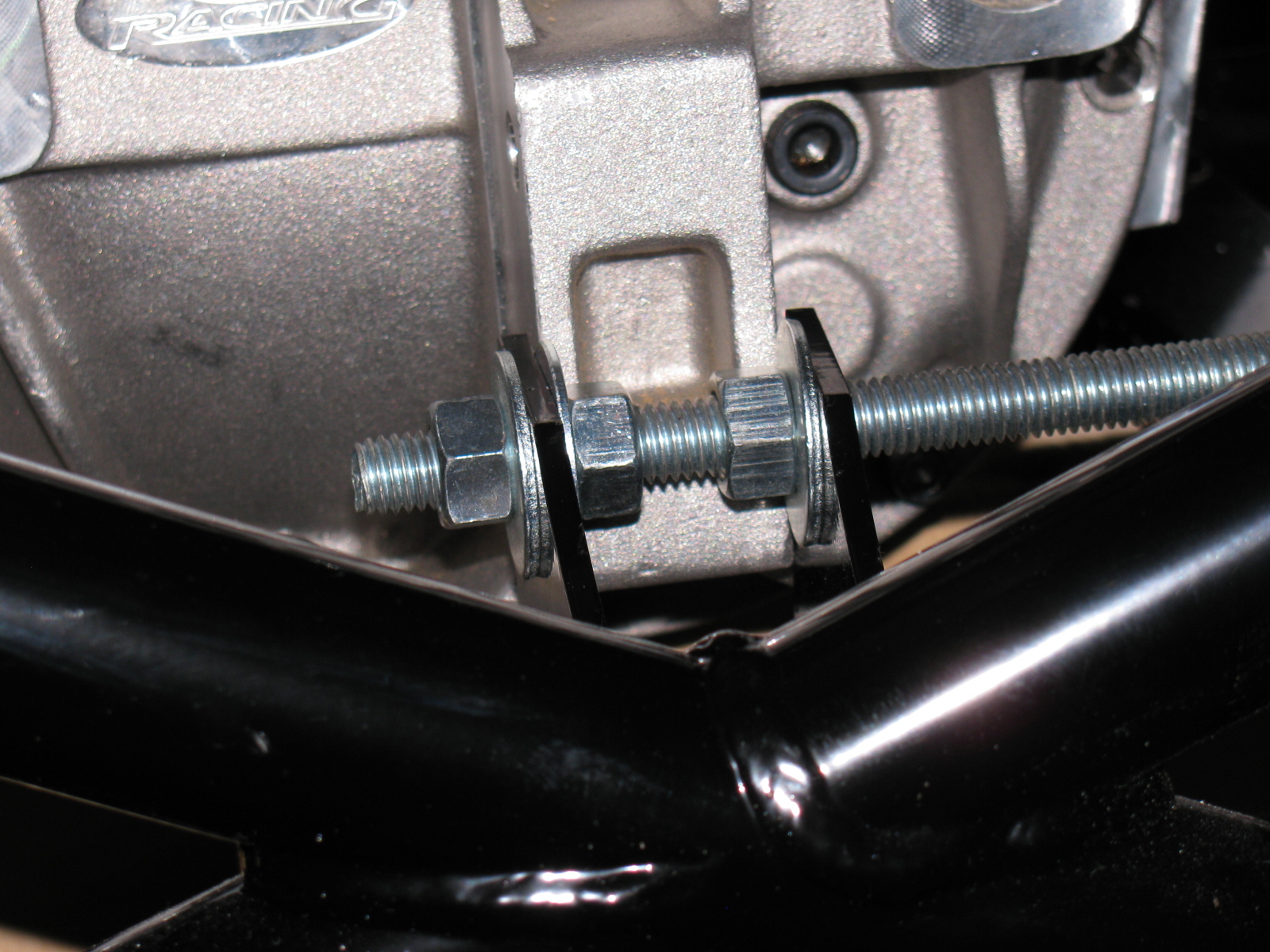
The rear mounting tabs (with the nice “5” logo laser-cut into them) are too close – use the threaded rod-expander trick to make it fit.
By the way – anyone else missing two nuts and bolts for the pumpkin mount? My parts list is correct, and yet I am still missing two fasteners for the standard width IRS differential.
I discovered I have the wrong adapter plates for the rear disc brakes, These are for the non-IRS version of the car. Jason at The Factory is sending the correct parts to me……

