Archive for the ‘Automotive’ Category


I spent the last two weekends in the garage, getting back to the Coupe Project. It was nice and relaxing to lay on the creeper, under the chassis and working with tools again.
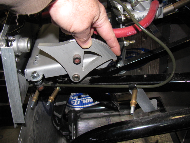
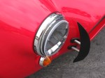
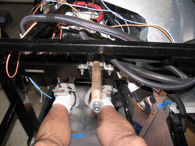
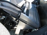
I had to modify the chassis in the pedal box area to allow more clutch pedal movement. This is a known issue in the Roadster forums, but not so much in the Coupe forums. This happened when Factory Five Racing changed the Wilwood pedal box – the old version would actually break. The new and improved pedal box moves the clutch pedal arm over to the left by about an inch or so, and the arm hits a brace, limiting pedal travel.
When the modification is done before the pedal box is bolted into place, it is a simple chore to make two cuts, chopping a small triangular cut into the frame member. This can be done with a reciprocating saw or maybe power jigsaw.
However, if the modification must be performed after the pedal box is bolted into place, the tube must be accessed from below, in an awkward angle. A small grinder tool would be ideal for this, but the only tool I have that will fit the space and the angle is a Dremel tool. It took me two half-day sessions to do this.


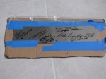
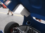
In the pictures above you can see the half-moon shape cutout I had to make. This is a view from under the chassis, looking up from the creeper. This will be painted black later. The tube looks normal from the top, so that is good. And clutch pedal travel is doubled, so free play adjustment range should be much better.
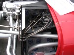
Since the brake system is installed, filled and bled, I removed the Clekos and riveted the lines in place. I changed several P-clip anchor points so it complies with my “routing and clipping manual” from the office. Unfortunately, I followed some other builders’ clipping, and mounted several p-clips upside down. Most of them will be under the car, and might be hidden from view when the car is finished. But I know they are upside down.
Here is a picture of how the clips should be mounted. This is the X-member in the front of the chassis.

Looks like I didn’t take a picture of the riveted clips. I will post them later.
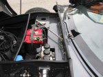
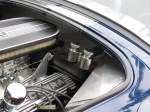
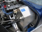
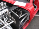
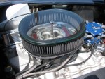
Next, I made a bracket to support the ECU for the MSD Atomic fuel injection system for my 302. This plate will secure the ECU and provide strain relief for the cables going in and out of the unit. It is on a plate so it can be easily removed if I have to work on the wiring or the ECU later. It is mounted with 1/4-20 stainless steel studs and nylon lock washers. It was raining so I was not able to paint this plate. Will have to do that at the next build session.
The passenger side footbox is on the left. Three stainless steel Allen head screws come through the wall and into the passenger box. The center photo shown the ECU engine cable going into the engine bay, and the right photo shows the MSD computer and plate inside the passenger footbox. Carpet will cover the interior, so a carpeted cover will be made to hide the ECU and wires when the car is finished.
I am also laying out the air conditioner system components on the chassis. I have to make several brackets and small boxes to mount the A/C components on the chassis.
As I was doing this work, I took another look at the battery box mentioned in an earlier post. It is installed with clecos so it can be removed. I think I want to mount the battery above the passenger footbox. Two reasons for this:
First, it will shorten the battery cables, decreasing the voltage drop.
Second, the “factory location” for the battery – in the rear center – blocks the rear axle pumpkin. So, when I have to change the oil or make adjustments, the battery must be disconnected and the battery and the box must be removed. Sounds like a painful procedure for a simple maintenance chore.
I will make a mock-up of this in my next build session. Stay tuned . . . .

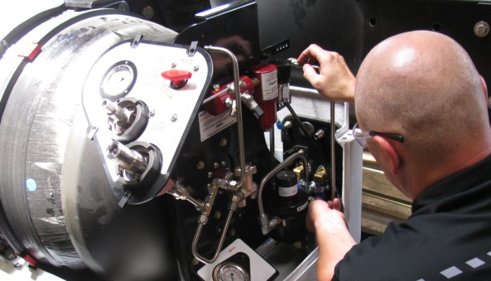
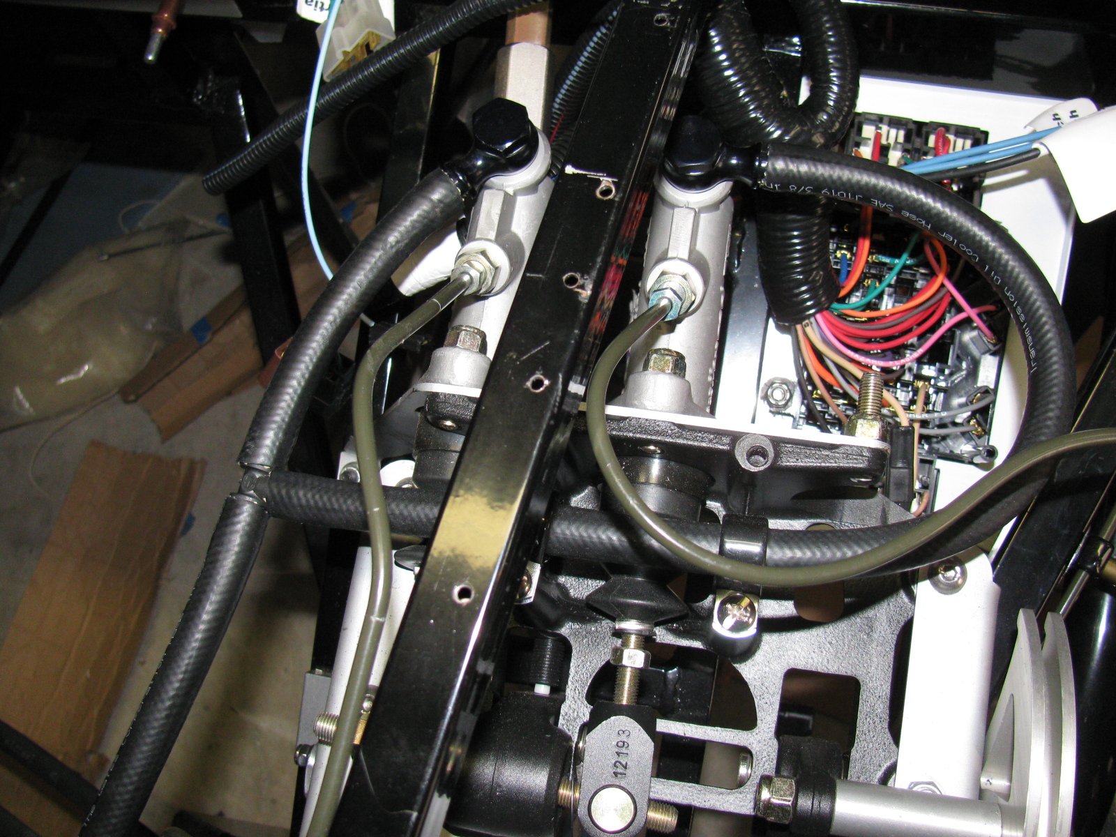
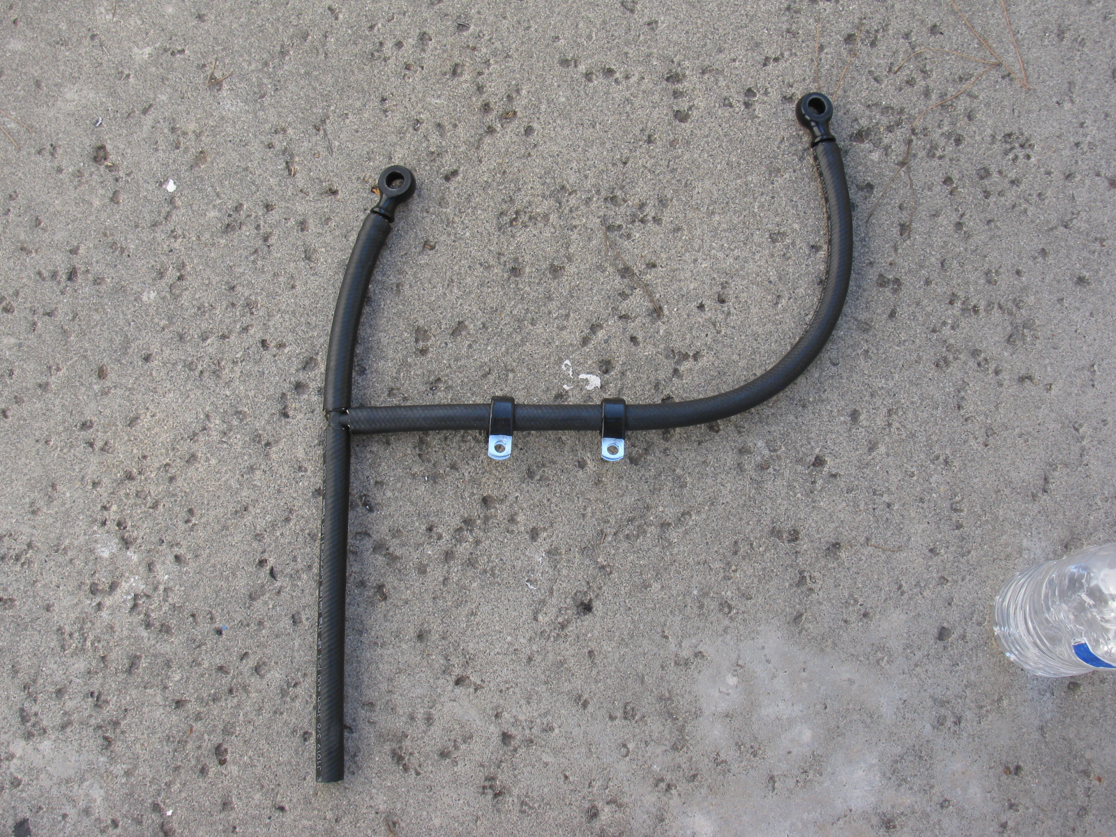
Working on a CNG vehicle fuel system
Repairing and maintaining a compressed natural gas (CNG) fuel system – with flammable gas and working pressures of 3,600 psi or more, can be safe if you understand and follow the rules.

CNG pressure zones determine to depressurize or defuel.
Read the full post here. . .

I made some “reference videos” of a few completed Type 65 Coupes to get ideas for my build. There are also other cars shown in the videos.
I used my GoPro Hero3 on a homemade extension handle so I could “reach into” places I normally would not be able to get to. The handle was designed to be an extension for my camera tripod, for macro photography, and it is a little less than two feet long.
I will make a longer handle – maybe 6 or 10 feet – to capture different angles with the GoPro. I also have an idea to make a remote panning feature for the camera on the handle.
I hope to make the new handle in time for the Maker Faire coming soon.
Go to my YouTube channel, and take a look at the Factory Five Racing Cruise-In videos. . . .
Overcast skies and 10 percent chance of rain, after months of drought conditions….
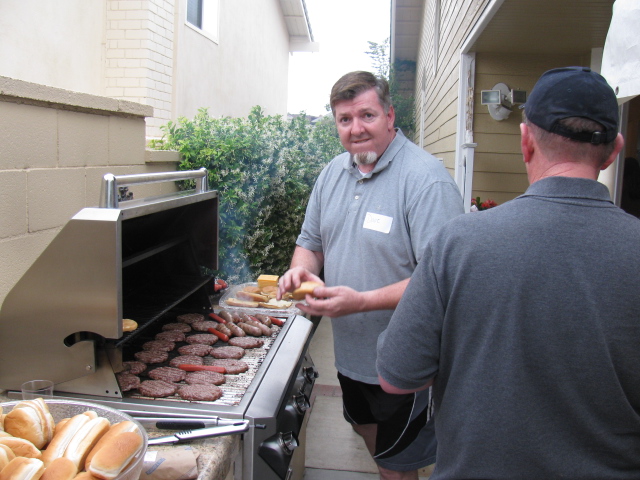
The Pre-Party
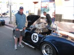
A generous tradition started by David Hodgkins. Here is our host at the BBQ, working hard to feed all of the guests. I met one of the Car Warriors builders from the East Coast Team, Mark Stackler.

David Hodgkins, our generous host of the HB Cruise-In Pre-Party
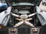
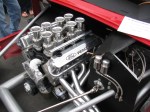
Another guest at the Pre-Party was Scott Merrell of Coupe Connection. He talked about the 8-stack induction system fitted on a Ford Coyote engine. Very interesting, and I may use that engine in my next project car.
The Event
More gray skies, but no mention in the forecast of rain. As usual for me, my focus was to gather as much info about Coupes as possible, so I can apply these ideas into my car project.
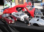
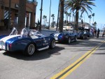
Also as usual, I had to look at all the other Factory Five Racing kit cars on display.
I noticed more completed 33 Hot Rods this year and more Coupes.
Highlights of the Day
I met and discussed body and paint with Jeff “Da Bat” Miller in the early morning. He has probably put the final finish on hundreds of Factory Five Racing cars over the years. Da Bat was the Body and Paint expert for the West Coast team on the Car Warriors Factory Five Hot Rod challenge.
I was lucky to meet and hang out with Karen Salvaggio and Jo Coddington as we visited with the builders and the cars on display. Karen and Jo were two members of the five lady team on the “All Girls Build” episode on Power Nation. The other ladies were Nan Gelhard, Cherielynn Westrich and Courtnie Provencher.
Here’s a picture of Karen on the left with Jo on the right. And that’s Sue from Just Get Dirty Garage in the middle. Sally Bean, one of the behind the scenes people from Factory Five, is in the background, making sure things are going as planned…..

Factory Five Racing Ladies

Factory Five Racing president Dave Smith introduces Jo Coddington to the crowd.
Meeting Peter Brock, BRE Racing
Peter Brock, the body designer of the Daytona Coupe, came to Huntington Beach for this event. I have several of Peter’s historical posters on my walls, but I wanted to meet him in person. Peter is a nice guy, and he truly loves the Factory Five Racing version of the famous Ferrari-killer from 1965.

Factory Five Racing president Dave Smith (right) introducing Peter Brock to the Cruise-In crowd. There’s Mark Stackler in the background.
The Fastest Factory Five Racing Coupe in the World
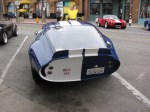
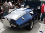
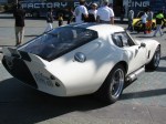
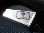
On display was the SoFast Racing Factory Five Racing Type 65 Coupe. This kit car holds a land speed record at the Bonneville Salt Flats. Allen Grant was there to sign autographs and display the car.
-

-
The fastest Factory Five Racing Type 65 Coupe and land speed record holder.
-
-
-

Watch this in-car video: Ride Along 200+ MPH Coupe at Bonneville
GoPro Videos
I made a few “walk around” videos with my new GoPro Hero 3. The footage is raw and needs some editing. I will post some after I do some editing.
Just as the event was ending, it started to rain. It was only a few minutes, but it managed to get stuff wet. I guess we can call it a California rainstorm. The local weather reports did not report any rainfall….
Here are some more pictures of this great annual event. Someday my Coupe will be there, too!
I did some measuring today and discovered the adjustable seat rails raise the seat too high for mounting in the enclosed cockpit – on a Roadster, an open car – this would not be a problem, and may help shorter drivers (under 6-foot) like me.
Stay tuned for an update as I re-modify the mounts by installing the rails on the side of the seat – as mentioned in the earlier post. Scroll to the entry by ChazC5ZX.
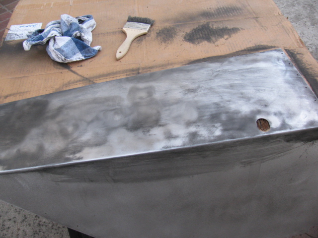
Last weekend, I decided to get back to work on the Coupe. I have to focus on getting everything ready for the engine installation. So, I started to mount the previously painted foot box aluminum.
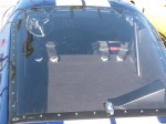
But I ran into a problem – the oily under body paint was not adhering well in some places, and the paint surface quality varied greatly. Here is a picture of what I mean…

Rather than just leaving it alone, I decided to remove all undercoated parts and re-finish them with truck bed liner paint. The truck bed liner paint is more consistent, is very hard and seems to adhere better than the under body paint.
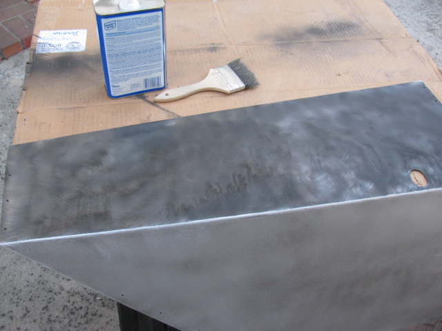
Taking off the greasy under coating was difficult, because the gooey paint clogged up the abrasive pads on my random orbit sander. So, I had to first use a wire brush on my drill to “scrape” off the greasy stuff, and then wash it down with acetone, like this:


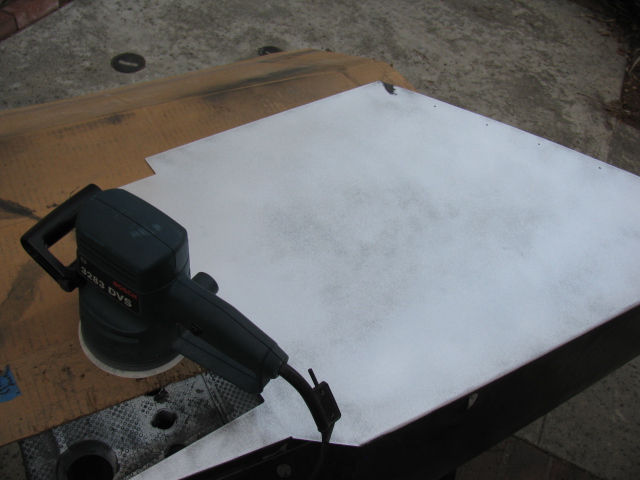
… and then sanded to bare metal with a 60 grit disc on my random orbit sander.

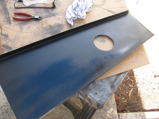
I washed the panels with dish washing liquid in my kitchen sink, and applied two coats of truck bed liner paint. Now the panels look much better. The truck bed paint has a slight wrinkle finish so I am not sure how hard this will be to keep clean. It is, however, better than that greasy under coating stuff. Here is a picture of the bottom surface of the transmission tunnel cover.

I will cover all interior surfaces with heat and sound barrier (Cool-It) and then put carpet over everything later.
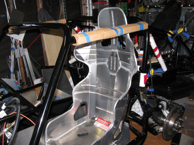
Since I am working on cockpit “fitment,” I wanted to dry-fit the Kirkey high back racing seats so I can adjust the position for pedal actuation.
The Factory Five Racing Complete Kit provides two options for seats, low-backs for the more traditional look, and a high back option that provides more back support. I went with the high backs. However, the seats come with nuts and bolts, and the instructions say to drill the seats and use the bolts to attach them to the floor.
I checked the forums and found a better solution. Thanks to posts by Rich A and rick8928, I copied what they did with their seat mounts. Their solution adds an adjustment feature to the seat mounts. The part numbers from Summit are still valid, although the prices have gone up a little. I bought two sets so the passenger seat will be adjustable, too. Thanks guys for helping me to not re-invent the wheel on this one!
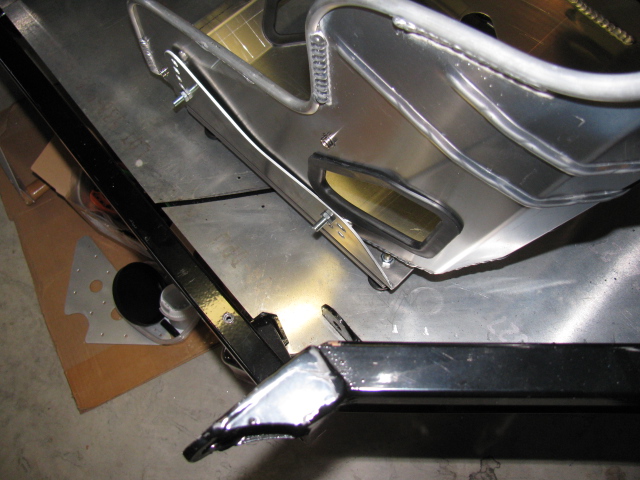
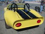
Here are some pictures of my version…


The last two images above show the seat belt mounting points.
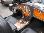
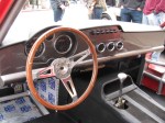
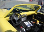
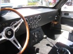
Here is a cockpit view of the pedal box.

I am glad I have the seat adjusters, it should make getting in and out of the car easier. It looks like I will have to adjust the seat forward in order to reach the pedals comfortably, and then I can push the seat back to get out (and in) the car.
Heel-toe should be okay, I will have to bolt the seats into the car and move the seat forward to make sure.

Sharp-eyed viewers noticed the left side of the driver foot box is missing. Indeed it is. I made a small modification to this part – I cut the tabs off of the mating panel, and added small angle aluminum to the front piece, so I can rivet (maybe screw in) this panel later.

I should probably do the same thing to the right side of the pedal box, so I can access the gas pedal mounts for adjustment, although the engine might be in the way.
Stay tuned, more to come on the Factory Five Racing Type 65 Coupe Project.
Not much to report on the Type 65 Coupe Project. I have been doing a lot of other things over the last few weeks. The heat has been making me lazy.
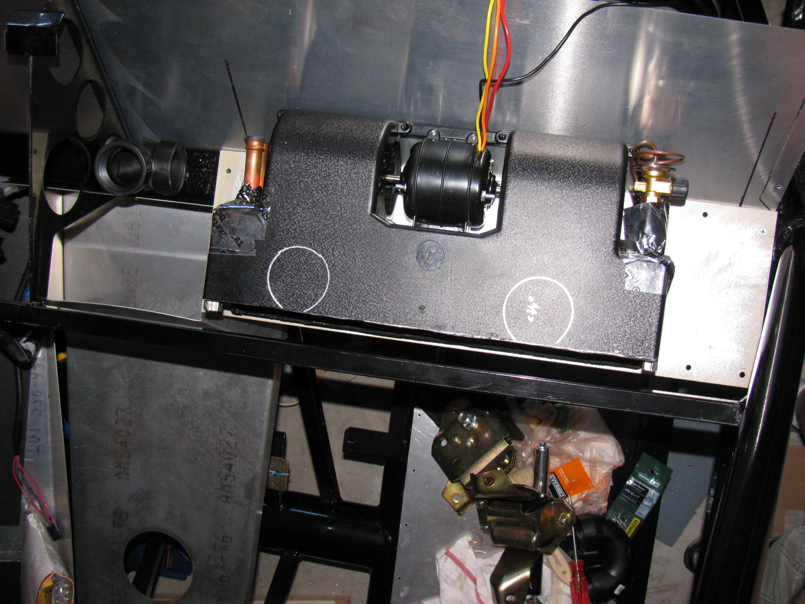
I decided to do some work on the A/C unit for the Coupe. I cut and chopped the housing cover for several hours, and then decided it might be easier to just make a whole new cover using fiberglass and resin. . . . I did some research on composites, epoxy resins, fiberglass and boat repair, and lost-foam casting. Interestingly, I am doing the same research for some stuff at work. I will try my hand at making a custom duct for the A/C unit. I have a layout in my mind, but there are a lot more things that need to go behind the dash panel besides the A/C ducts. The new cover/duct will have to make several 90- and 180-degree bends. I hope to avoid the use of too many fittings by making a single duct/top cover for the A/C unit. Maybe it should be called a “manifold” instead.
Here are some pictures of the air conditioner and the “dry fit” of where it will mount.


I also re-installed the firewall. I had to take it off and re-paint it with a higher quality silver paint. I do not have pictures of this, but it does look better than before. The paint is “harder” than the other paint I used.
Next, I removed the “bad” brake hoses originally from the Complete Kit and replaced them with the proper red hose from the third technical bulletin from Factory Five Racing. This is the hose going from the reservoir to the master cylinders. The new hose is much softer and easily slipped over the fittings. I hope they won’t leak. We will find out soon when I fill and bleed the system.


I also started to look at engine hoist options – I want to drop the engine in SOON!

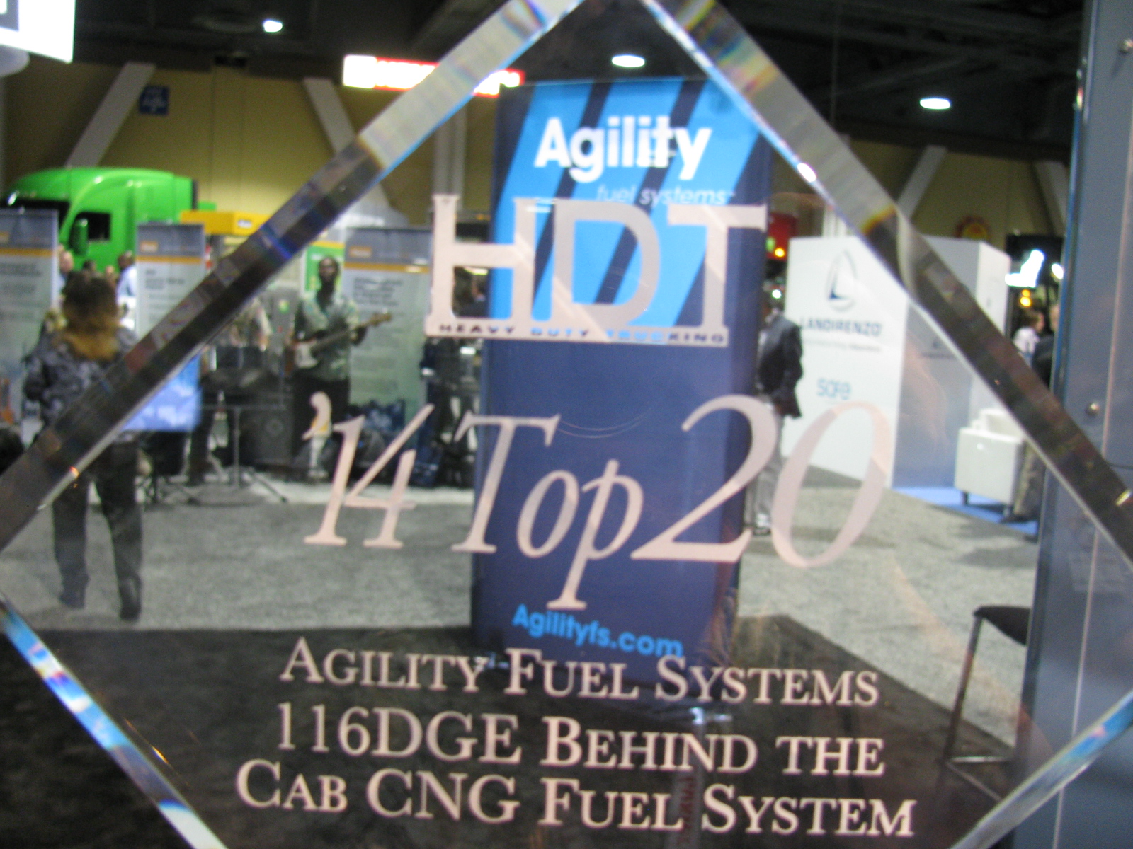
Today’s lead photo — an award we received…. The Agility Fuel Systems 116 DGE CNG Fuel System won a Top 20 Award from Heavy Duty Trucking – see more on the HDT website.

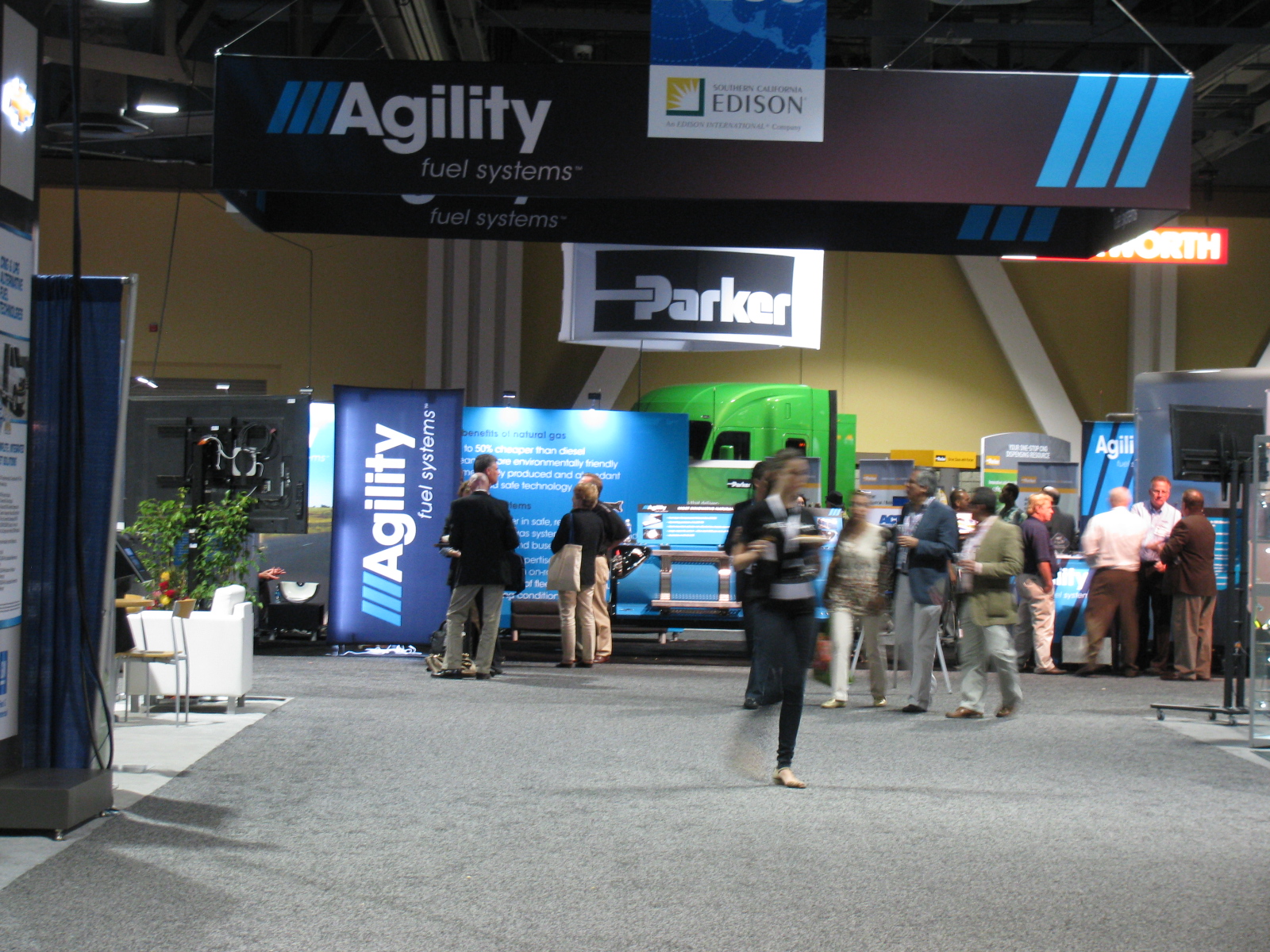
Our excellent booth location made it easy for visitors to find us. . . .

Left: Luis Salem, VP Marketing and Sales, explains the features and advantages of the new Agility Fuel Systems behind the cab (BTC) CNG fuel system to John Keltner of Daimler Trucks North America (DTNA).

I wish regular gas is less than $4 per gallon. I paid four-something per gallon last week filling my Prius . . .
And perhaps the biggest buzz on the show floor was the reaction to this news release we issued during the ACT show. . .
And this one, too. . .

The lead photo for this entry is Erik Hansen’ electric 818 cockpit. It is in “go kart” stage (a work in-progress), without a body. Click here to read Erik’s Electric 818 build blog.
By the way, Erik Hansen was part of the West Coast Team in the show “Car Warriors” in which a team of West Coast car builders competed against an East Coast team. They had to build a Factory Five ’33 Hot Rod in 48 hours. Amazing. Click here to learn more details about this competition
I spent most of the day at the 7th Annual Factory Five Cruise-In. It was great to see some of the builder/owners from the previous year, and I also met a lot of builders for the first time. I even met several of the Factory Five staff, including Scott “Honey Badger” Bell; Jim Schenck, Director of R and D; Tony Zullo, Tech Manager; and Sally Bean, Marketing at Factory Five, who does a ton of work behind the scenes of these great get-togethers.
Two cars were un-veiled today:
First, an “All-Women 427 Build Team” Factory Five Racing Roadster. The ladies built the car in one week. The build story will be on PowerNation’s “Detroit Muscle” TV in May.
Second, a special, limited edition Hot Rod magazine ’33 Hot Rod. Only 33 of these will be made, and for the first time, Factory Five will be selling the 33 ‘33s as fully-built cars. Two engines will be offered, a monster Ford engine, shown here, and a Chevy engine. I do not recall the details, but I will post them here as an update as soon as I can verify the information.
This year, I planned to gather as much information and pictures on the Type 65 Coupe, since I am always looking for ideas to include in my car. But – with so many beautiful Roadsters on display, I had to look at those closely, too.
Here are some random images from the great car show!
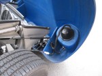
After something like three or four false starts, I finally settled on a way to mount the external fuel pump on my Coupe. The final solution is so simple, I feel stupid….
First, I tried mounting the pump on the lower brace, under the IRS pumpkin. But that just did not look right, and it was difficult to access from either above or below the car. Then I tried mounting the pump on the Factory Five Metal battery box, but discovered the battery box blocks access to the fill and drain plugs on the differential.
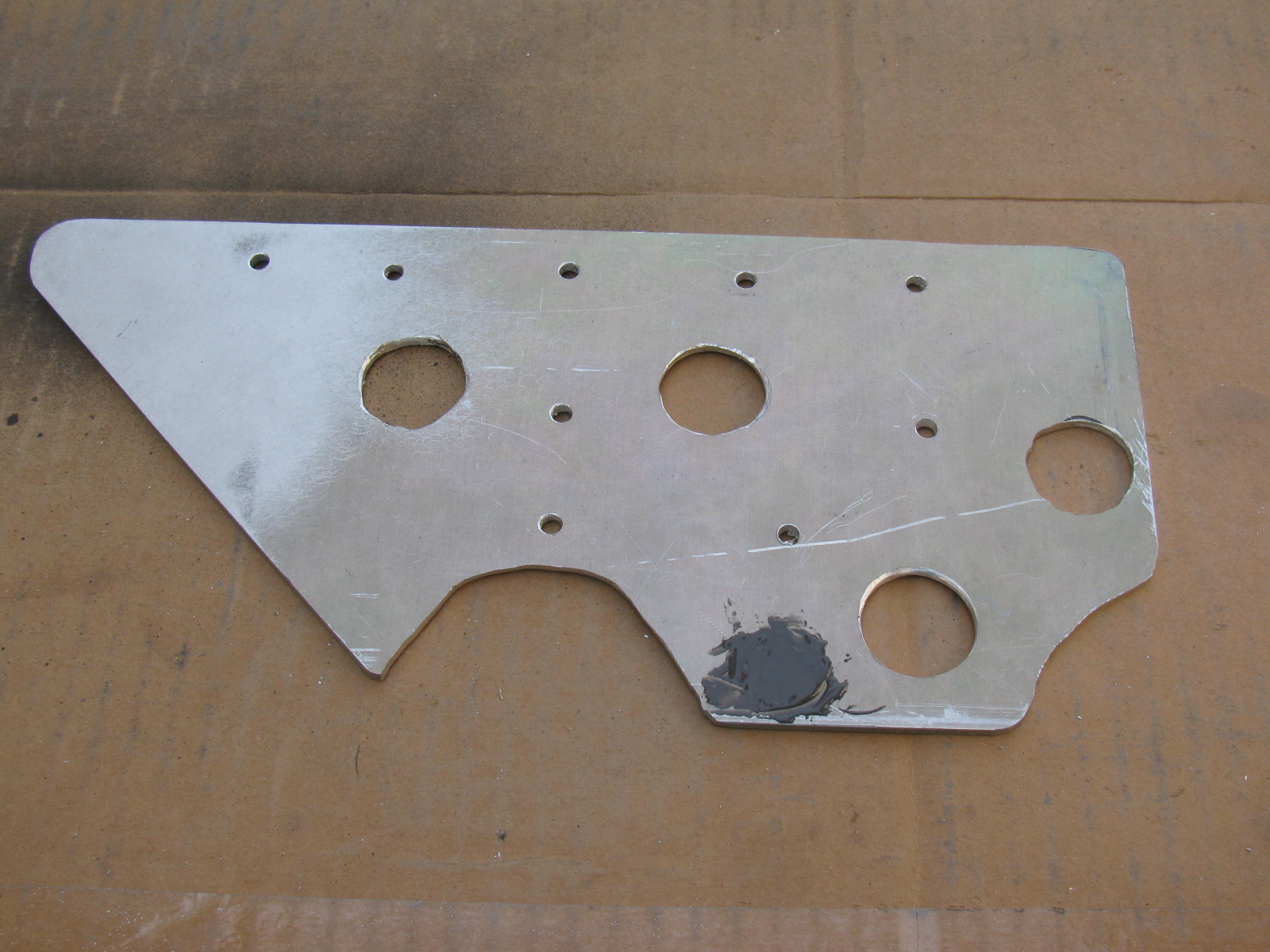
Here is the final answer, a simple, flat plate of 1/8-inch aluminum. This will help simplify the fuel hose routing, too.

More Fabrication
I made a pair of triangular plates to create a bulkhead to hold the e-brake cable and the fuel hoses (one for supply to the engine and one for the return into the tank) on the passenger side of the chassis. An identical plate for the driver side will be used for the other e-brake cable and any wiring harness going to the rear of the car.
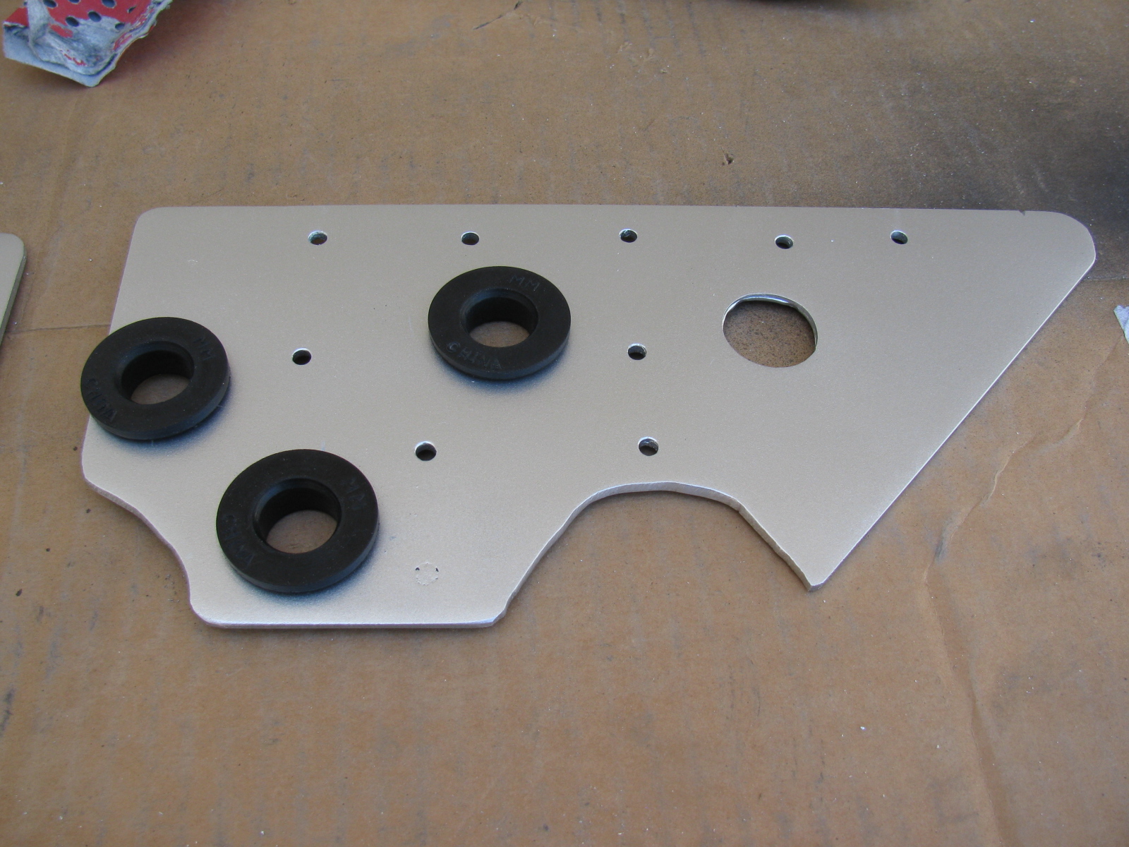
Since the 1/8-inch aluminum plate I am using for these brackets is scrap material, some extra holes are sometimes included in the items I make. When I am not able to re-use existing holes, I patch them with JB Weld or epoxy, then paint the item with high temperature BBQ paint. These brackets are finished in silver.


The large holes are cushioned with a PCV grommet; it is thick and large enough to pass the 3/8-inch fuel lines nicely.
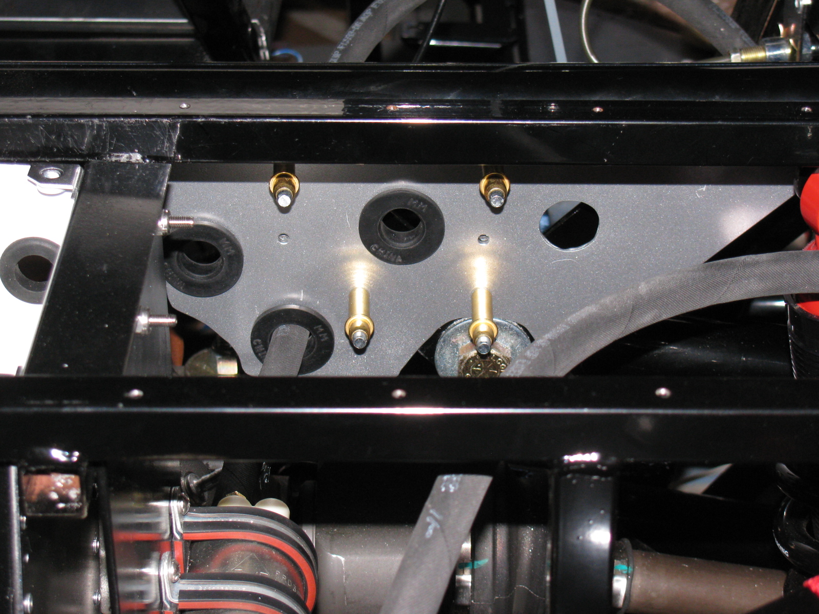
Here are some views of the passenger-side bracket installed with Clecos:


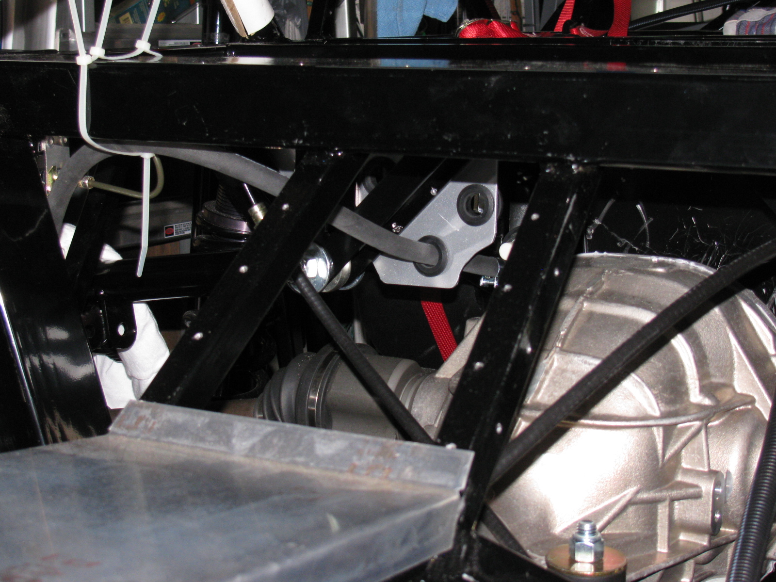
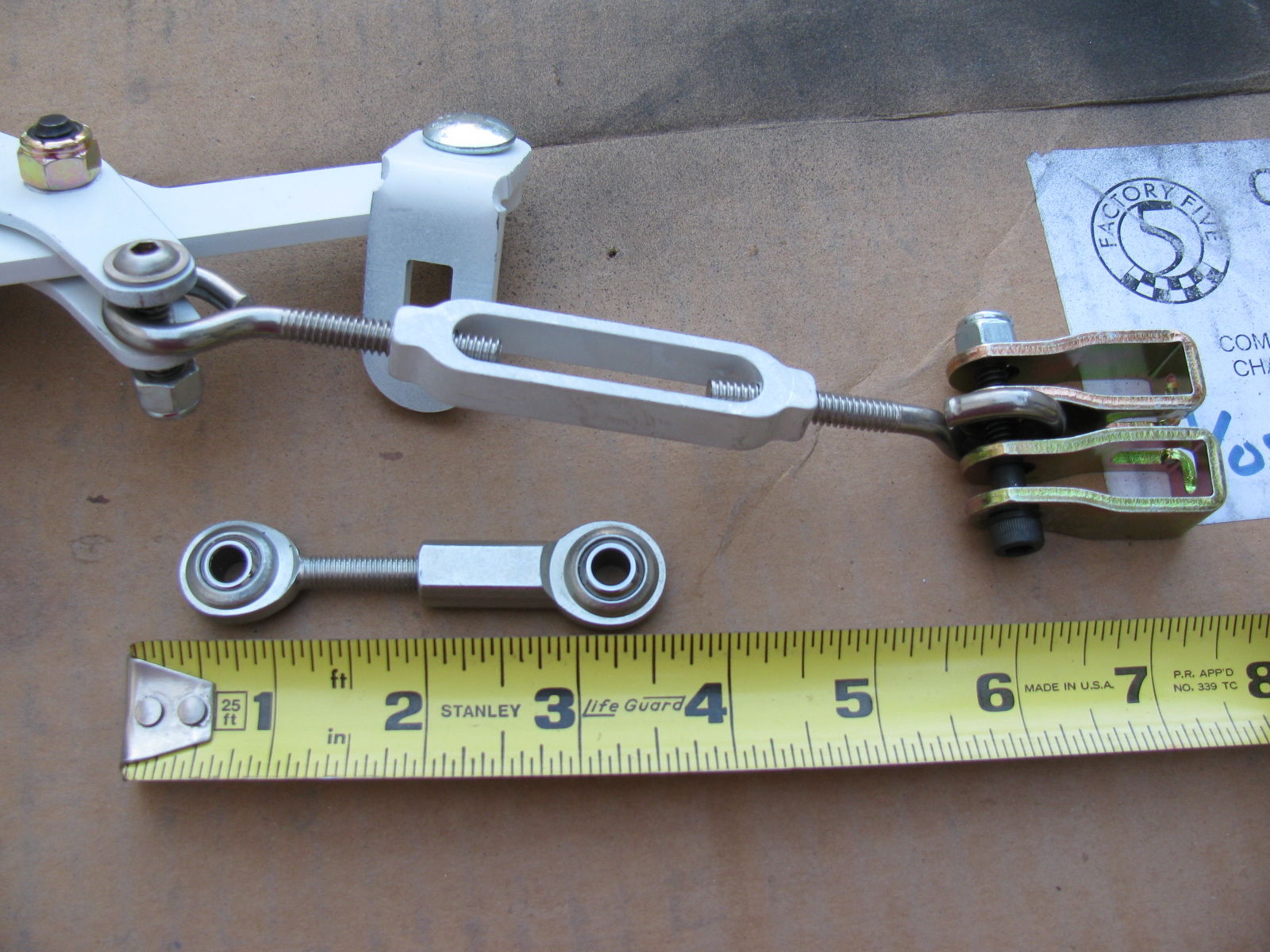
Next, I started laying out the e-brake cables and the complete kit e-brake handle. When I installed the rear brakes, I thought the cables looked too short. And last night I noticed that I am correct – the cables supplied with the IRS brake kit are about four to six inches too short.
I may have a solution to this, based on some Forum postings on this same topic — see the photo below. I do not like the turn buckle from the hardware store, I think I should replace it with a stainless steel clevis six to eight inches long to allow for adjustment. (McMaster-Carr items. . . )

UPDATE: I ordered an e-brake kit from Richard Oben of North Race Cars. (The same place I ordered my air conditioner – yet to be installed). The kit will move the e-brake to a more practical location at the top of the transmission tunnel.
Many builders of the Roadster as well as the Coupe do not like the way the brake cables rub against the big four inch tube. I will make a small Teflon block and mount it to the bottom of the chassis so the cable can slide more easily, and make it look much nicer. More details when I get to that step.
Main Wire Harness
I started laying out the main wire harness. A few weeks ago, I painted the fuse panel with white appliance epoxy paint. This will brighten up the underside of the dash and will prevent corrosion. Based on something I read on the Roadster section of one of the F5R Forums, I added a small hinge to the fuse panel mounting plate. You can see the hinge on the right side of the bracket in this picture:

However, this is bad advice, at least for my Coupe application. This is not a good thing to do for several reasons:
1) It moves the fuse block about a quarter-inch forward into the footbox, and adds strain to several wires in the Ron Francis harness supplied with the Complete Kit.
2) The reason for the hinge was to make it possible to swing the entire panel down for easy servicing. However, this is impossible, since there is not enough slack and the thick harness will not allow the fuse panel to simply “swing down.”
3) The mounting holes must be very close to the edge of the 2-inch rail. Removing the hinge makes a better location for the mounting screws.
After removing the hinge, and mounting the fuse panel per the instructions, I noticed some “squishiness” in the fuse panel, which I do not like. I have not seen this mentioned in any post so I thought I would bring it up here.
The fuse panel is a piece of thin aluminum, laser cut to shape to hold the plastic fuse panel. Three zip screws (the self-tapping hex-head screws that held the cockpit aluminum in place when the kit was shipped) fasten it in place under the driver footbox, near the steering column.
All fine and dandy, but the fourth corner is “floating in space” and flexes easily. I decided to add a small aluminum bracket to make the fuse panel stronger (flex less). I hope the bracket does not get in the way of anything to be mounted later….