Archive for the ‘footbox’ Tag


I spent the last two weekends in the garage, getting back to the Coupe Project. It was nice and relaxing to lay on the creeper, under the chassis and working with tools again.
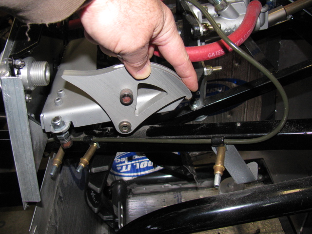
I had to modify the chassis in the pedal box area to allow more clutch pedal movement. This is a known issue in the Roadster forums, but not so much in the Coupe forums. This happened when Factory Five Racing changed the Wilwood pedal box – the old version would actually break. The new and improved pedal box moves the clutch pedal arm over to the left by about an inch or so, and the arm hits a brace, limiting pedal travel.
When the modification is done before the pedal box is bolted into place, it is a simple chore to make two cuts, chopping a small triangular cut into the frame member. This can be done with a reciprocating saw or maybe power jigsaw.
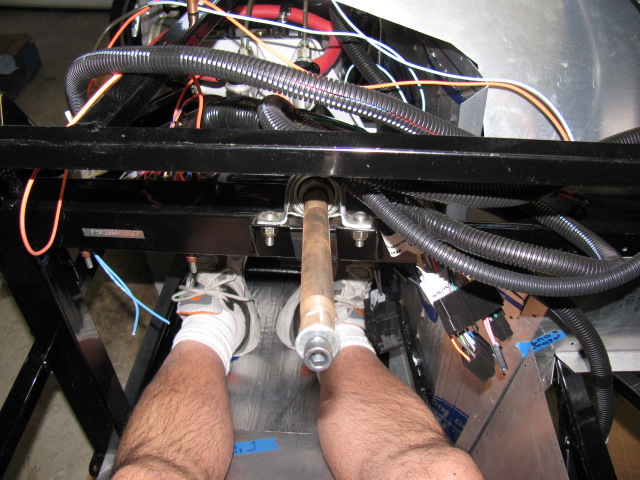
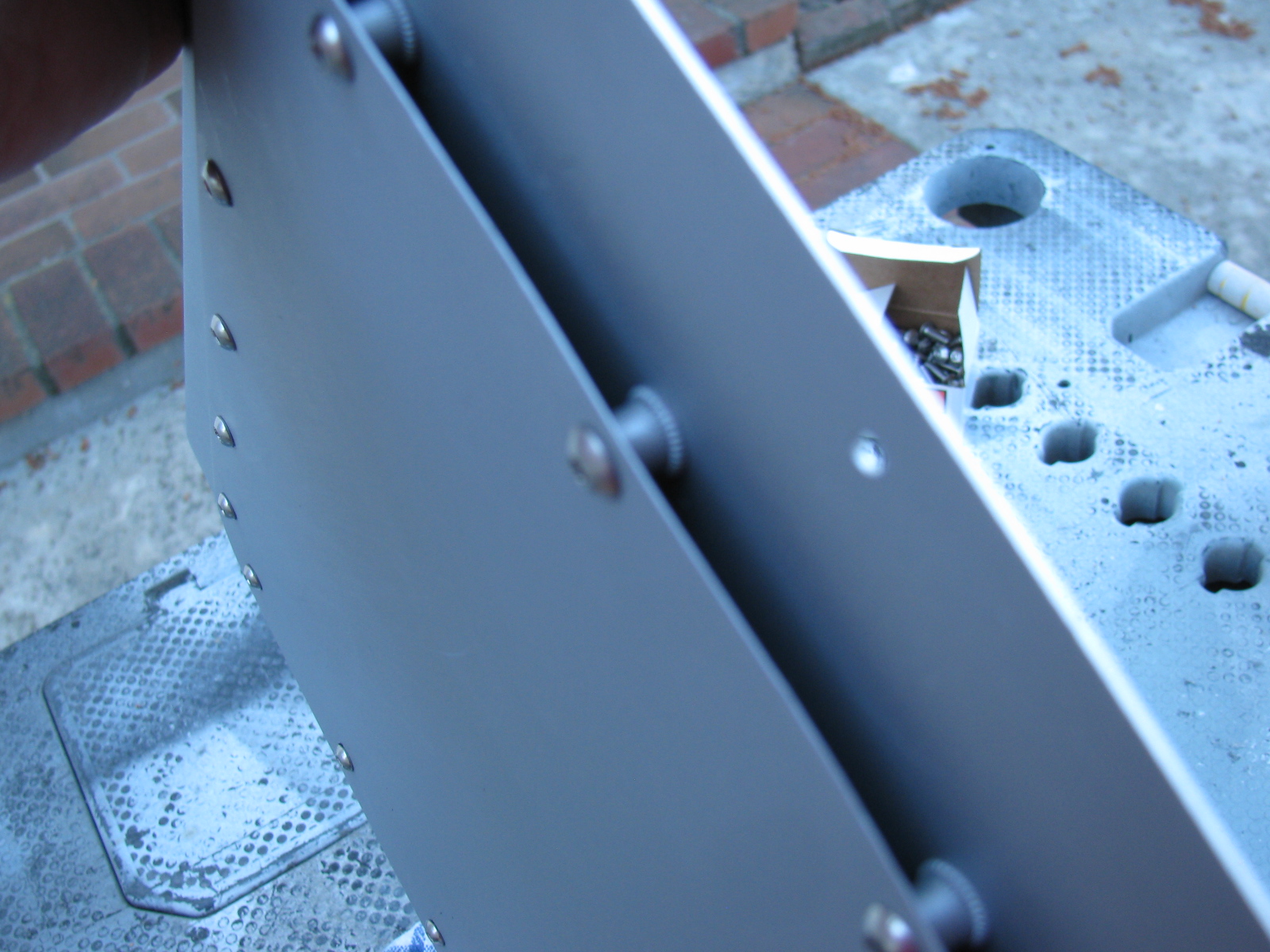
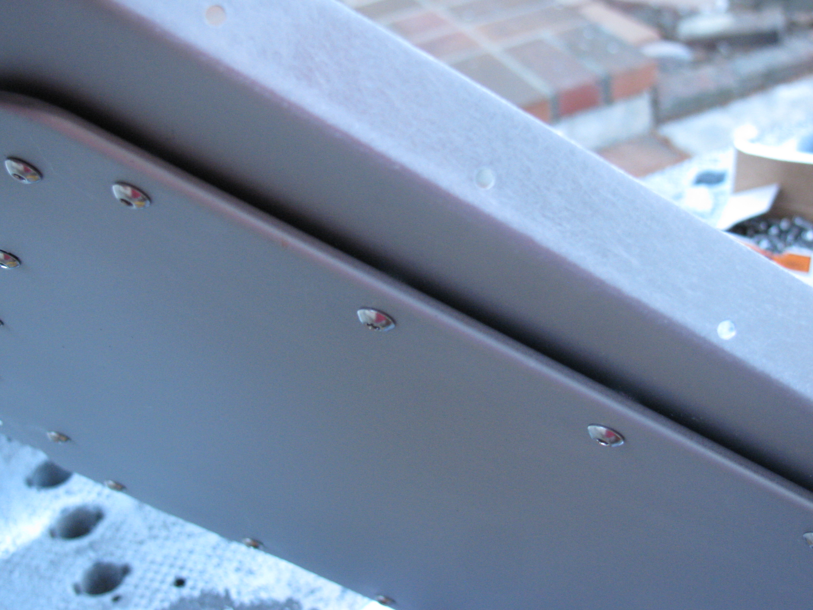
However, if the modification must be performed after the pedal box is bolted into place, the tube must be accessed from below, in an awkward angle. A small grinder tool would be ideal for this, but the only tool I have that will fit the space and the angle is a Dremel tool. It took me two half-day sessions to do this.


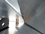
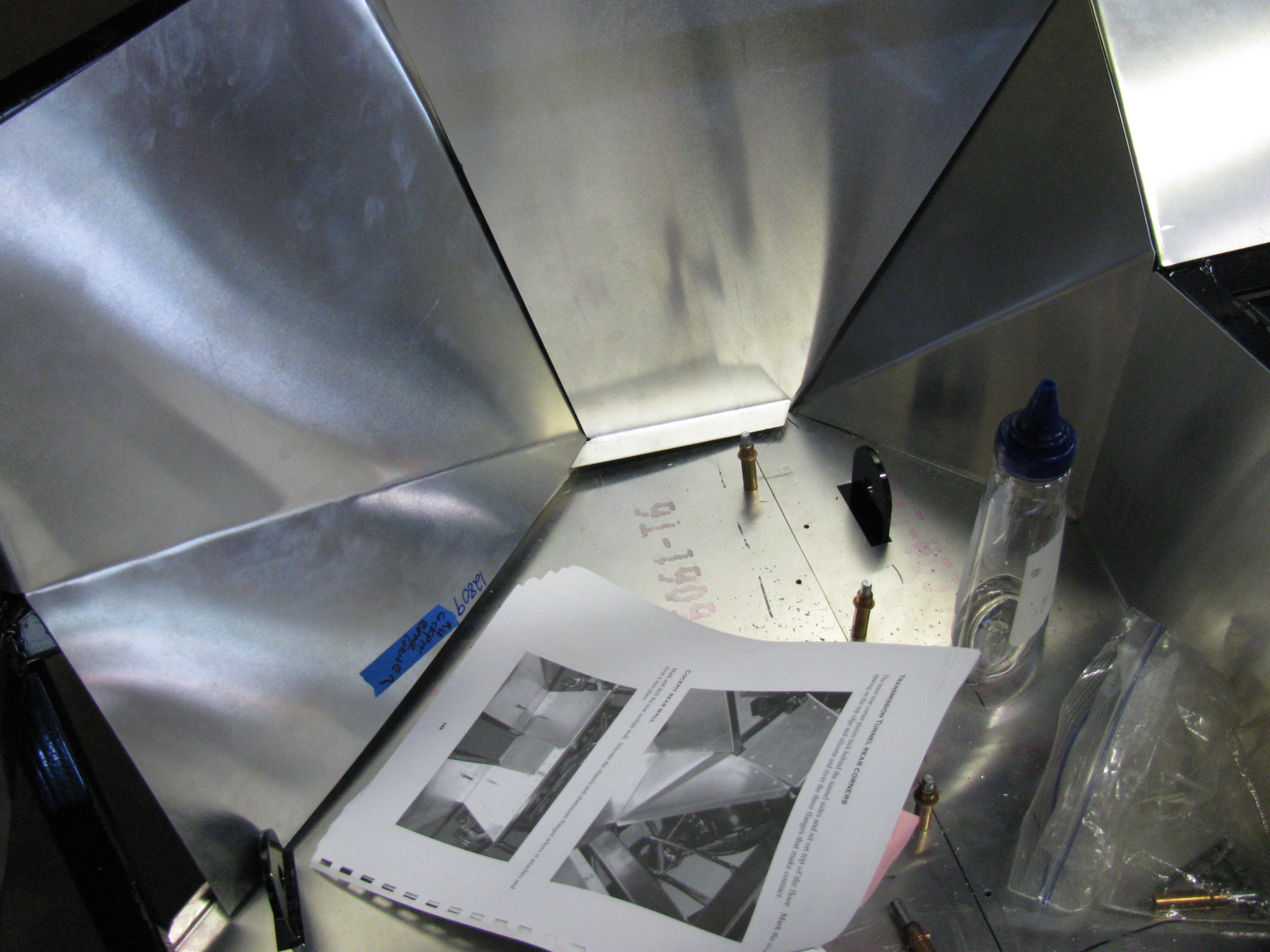
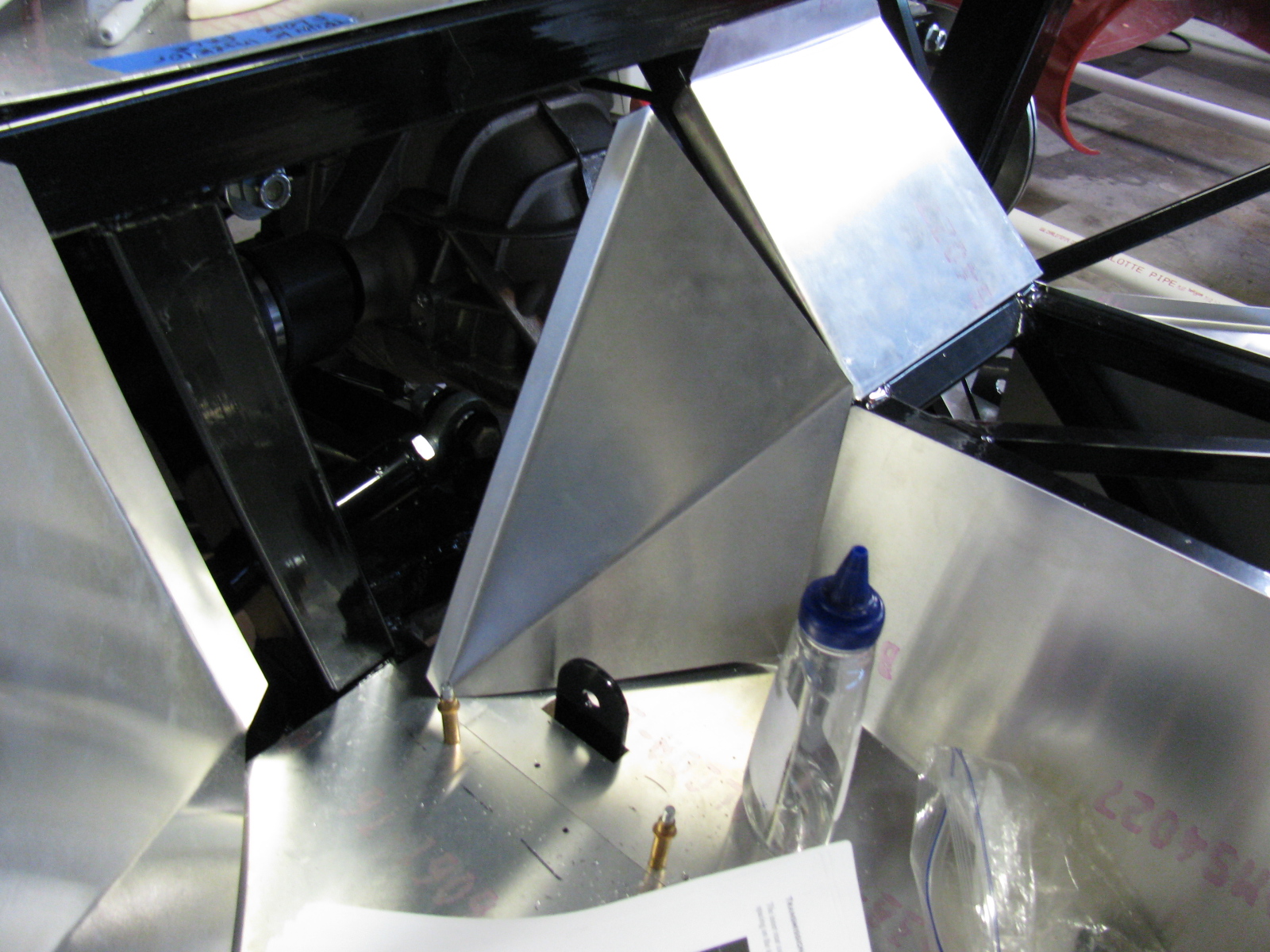
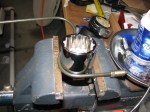
In the pictures above you can see the half-moon shape cutout I had to make. This is a view from under the chassis, looking up from the creeper. This will be painted black later. The tube looks normal from the top, so that is good. And clutch pedal travel is doubled, so free play adjustment range should be much better.
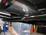
Since the brake system is installed, filled and bled, I removed the Clekos and riveted the lines in place. I changed several P-clip anchor points so it complies with my “routing and clipping manual” from the office. Unfortunately, I followed some other builders’ clipping, and mounted several p-clips upside down. Most of them will be under the car, and might be hidden from view when the car is finished. But I know they are upside down.
Here is a picture of how the clips should be mounted. This is the X-member in the front of the chassis.

Looks like I didn’t take a picture of the riveted clips. I will post them later.
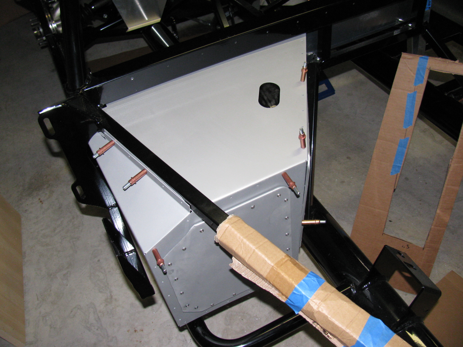
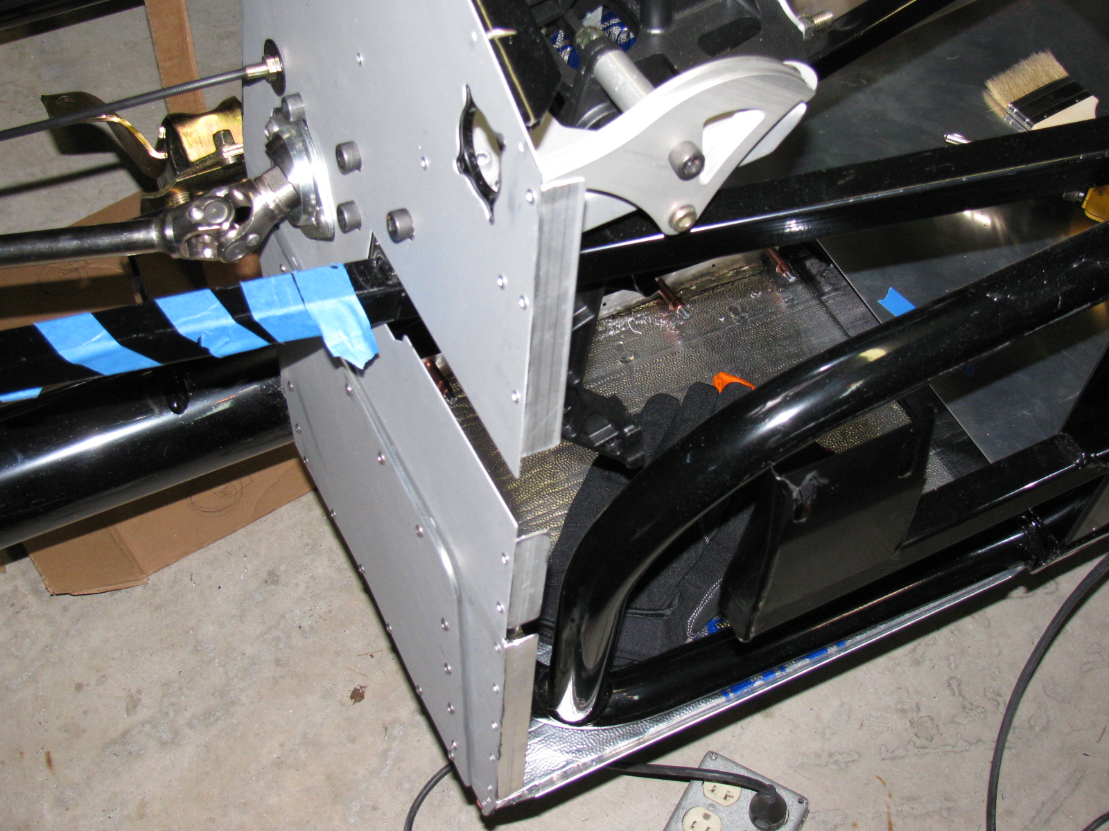
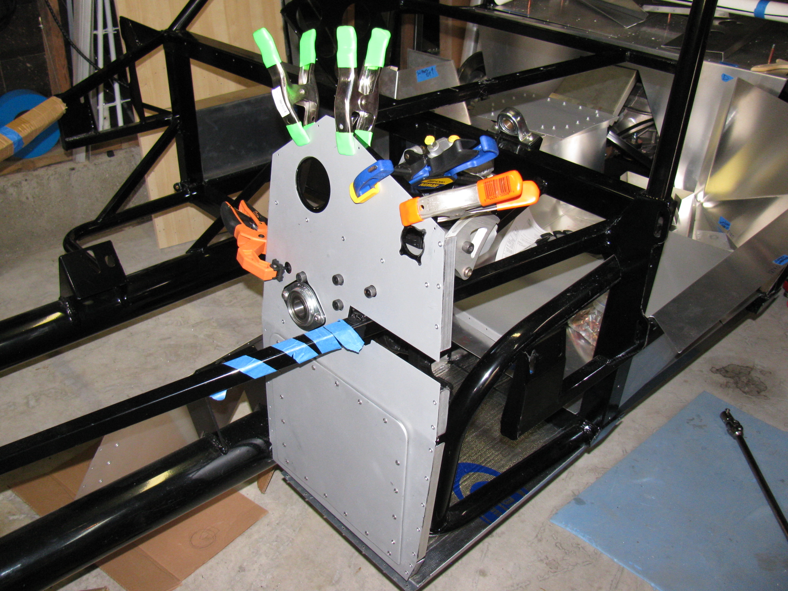
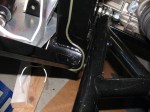
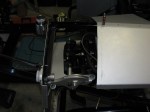
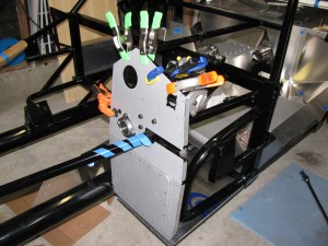
Next, I made a bracket to support the ECU for the MSD Atomic fuel injection system for my 302. This plate will secure the ECU and provide strain relief for the cables going in and out of the unit. It is on a plate so it can be easily removed if I have to work on the wiring or the ECU later. It is mounted with 1/4-20 stainless steel studs and nylon lock washers. It was raining so I was not able to paint this plate. Will have to do that at the next build session.
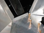
The passenger side footbox is on the left. Three stainless steel Allen head screws come through the wall and into the passenger box. The center photo shown the ECU engine cable going into the engine bay, and the right photo shows the MSD computer and plate inside the passenger footbox. Carpet will cover the interior, so a carpeted cover will be made to hide the ECU and wires when the car is finished.
I am also laying out the air conditioner system components on the chassis. I have to make several brackets and small boxes to mount the A/C components on the chassis.
As I was doing this work, I took another look at the battery box mentioned in an earlier post. It is installed with clecos so it can be removed. I think I want to mount the battery above the passenger footbox. Two reasons for this:
First, it will shorten the battery cables, decreasing the voltage drop.
Second, the “factory location” for the battery – in the rear center – blocks the rear axle pumpkin. So, when I have to change the oil or make adjustments, the battery must be disconnected and the battery and the box must be removed. Sounds like a painful procedure for a simple maintenance chore.
I will make a mock-up of this in my next build session. Stay tuned . . . .
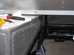
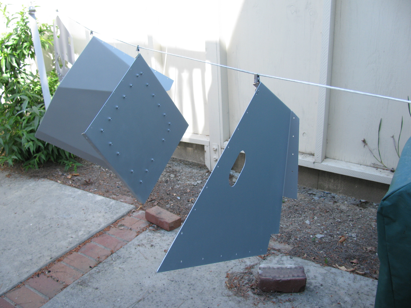
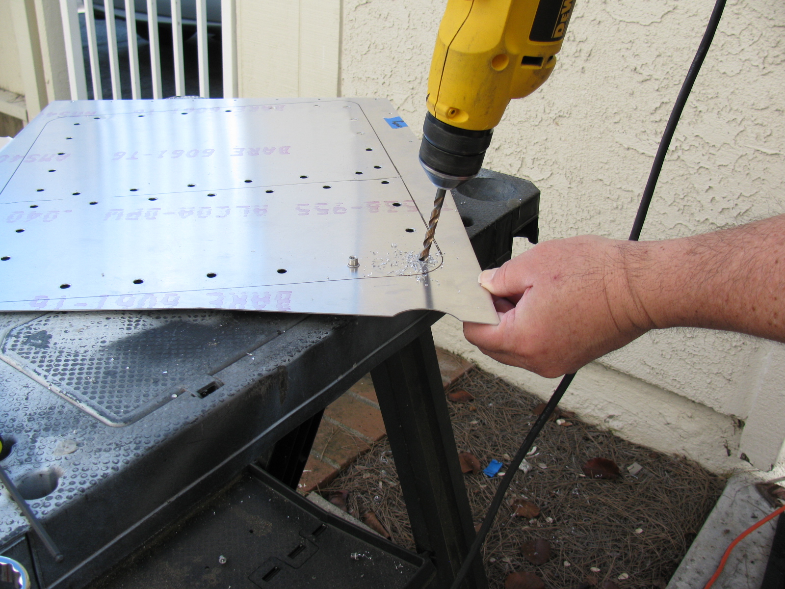
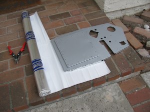
Last weekend, I decided to get back to work on the Coupe. I have to focus on getting everything ready for the engine installation. So, I started to mount the previously painted foot box aluminum.
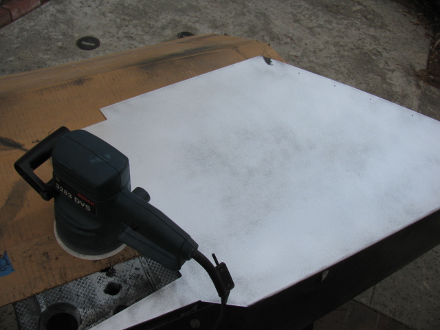
But I ran into a problem – the oily under body paint was not adhering well in some places, and the paint surface quality varied greatly. Here is a picture of what I mean…

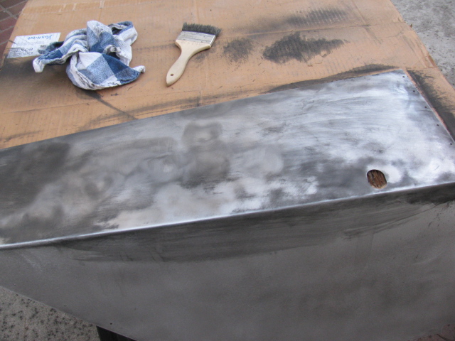
Rather than just leaving it alone, I decided to remove all undercoated parts and re-finish them with truck bed liner paint. The truck bed liner paint is more consistent, is very hard and seems to adhere better than the under body paint.
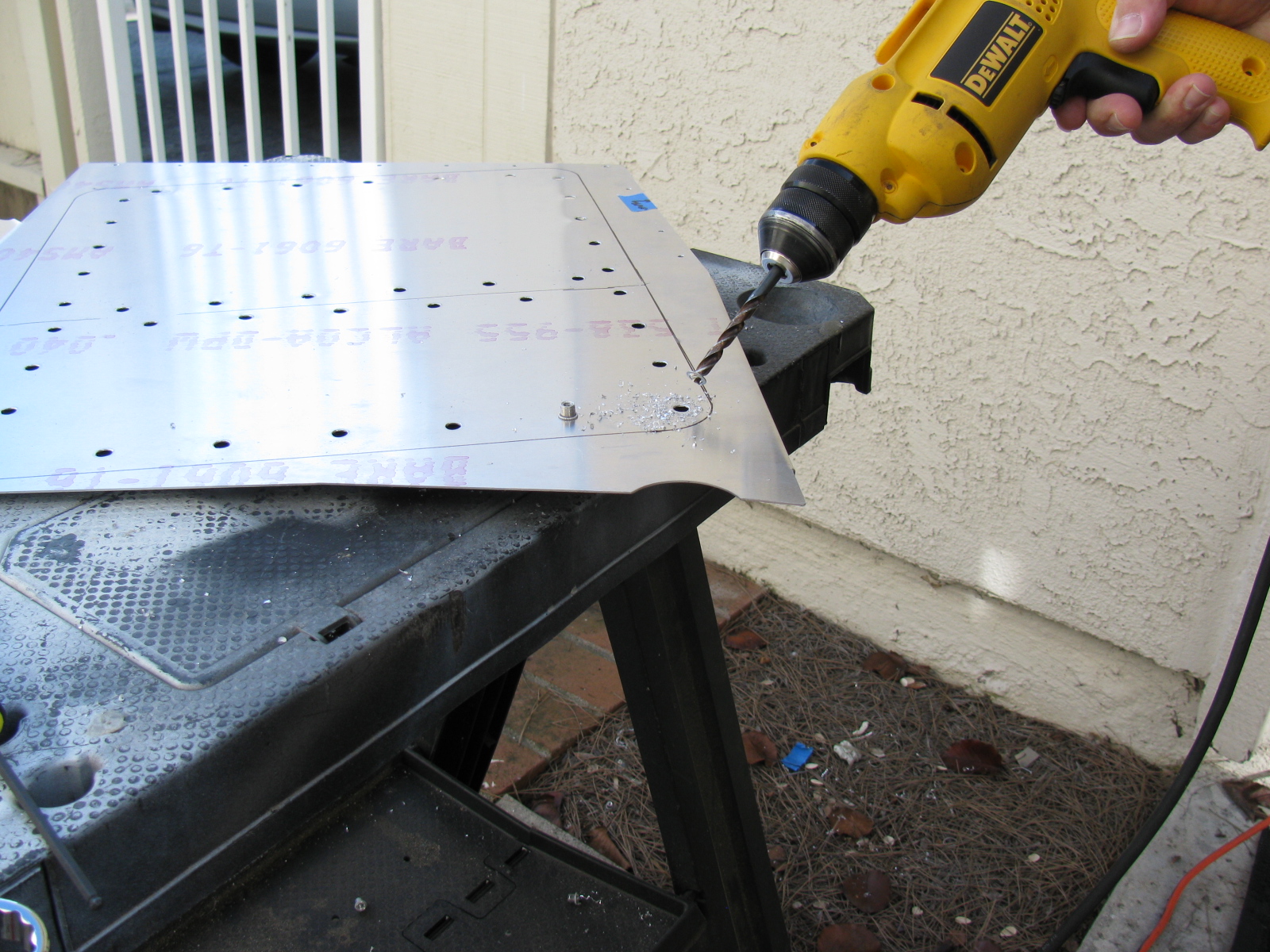
Taking off the greasy under coating was difficult, because the gooey paint clogged up the abrasive pads on my random orbit sander. So, I had to first use a wire brush on my drill to “scrape” off the greasy stuff, and then wash it down with acetone, like this:


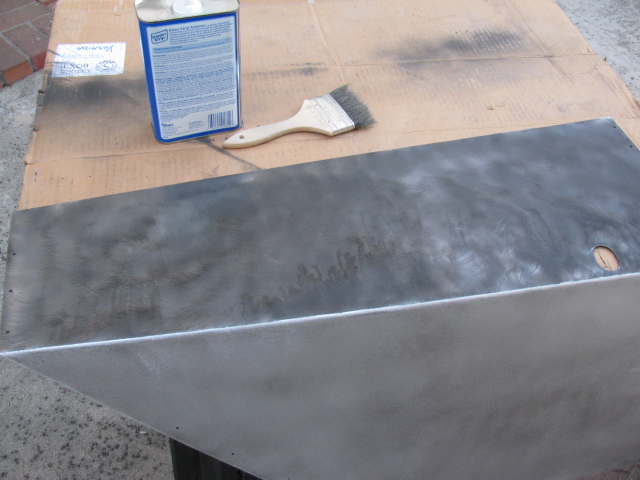
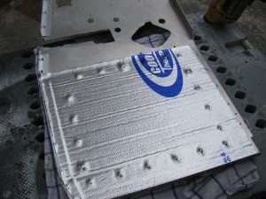
… and then sanded to bare metal with a 60 grit disc on my random orbit sander.

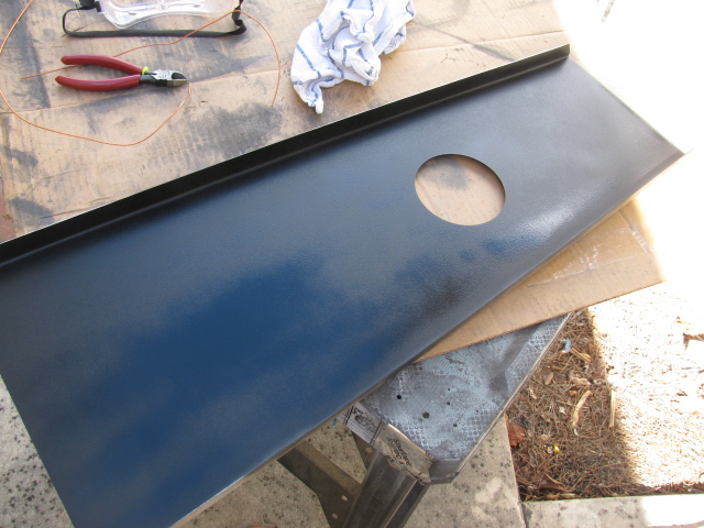
I washed the panels with dish washing liquid in my kitchen sink, and applied two coats of truck bed liner paint. Now the panels look much better. The truck bed paint has a slight wrinkle finish so I am not sure how hard this will be to keep clean. It is, however, better than that greasy under coating stuff. Here is a picture of the bottom surface of the transmission tunnel cover.

I will cover all interior surfaces with heat and sound barrier (Cool-It) and then put carpet over everything later.
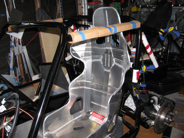
Since I am working on cockpit “fitment,” I wanted to dry-fit the Kirkey high back racing seats so I can adjust the position for pedal actuation.
The Factory Five Racing Complete Kit provides two options for seats, low-backs for the more traditional look, and a high back option that provides more back support. I went with the high backs. However, the seats come with nuts and bolts, and the instructions say to drill the seats and use the bolts to attach them to the floor.
I checked the forums and found a better solution. Thanks to posts by Rich A and rick8928, I copied what they did with their seat mounts. Their solution adds an adjustment feature to the seat mounts. The part numbers from Summit are still valid, although the prices have gone up a little. I bought two sets so the passenger seat will be adjustable, too. Thanks guys for helping me to not re-invent the wheel on this one!
Here are some pictures of my version…


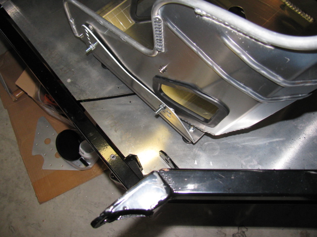
The last two images above show the seat belt mounting points.
Here is a cockpit view of the pedal box.

I am glad I have the seat adjusters, it should make getting in and out of the car easier. It looks like I will have to adjust the seat forward in order to reach the pedals comfortably, and then I can push the seat back to get out (and in) the car.
Heel-toe should be okay, I will have to bolt the seats into the car and move the seat forward to make sure.

Sharp-eyed viewers noticed the left side of the driver foot box is missing. Indeed it is. I made a small modification to this part – I cut the tabs off of the mating panel, and added small angle aluminum to the front piece, so I can rivet (maybe screw in) this panel later.

I should probably do the same thing to the right side of the pedal box, so I can access the gas pedal mounts for adjustment, although the engine might be in the way.
Stay tuned, more to come on the Factory Five Racing Type 65 Coupe Project.
After something like three or four false starts, I finally settled on a way to mount the external fuel pump on my Coupe. The final solution is so simple, I feel stupid….
First, I tried mounting the pump on the lower brace, under the IRS pumpkin. But that just did not look right, and it was difficult to access from either above or below the car. Then I tried mounting the pump on the Factory Five Metal battery box, but discovered the battery box blocks access to the fill and drain plugs on the differential.
Here is the final answer, a simple, flat plate of 1/8-inch aluminum. This will help simplify the fuel hose routing, too.

More Fabrication
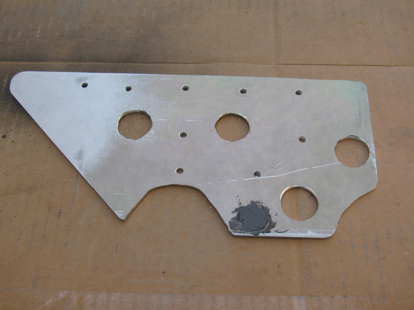
I made a pair of triangular plates to create a bulkhead to hold the e-brake cable and the fuel hoses (one for supply to the engine and one for the return into the tank) on the passenger side of the chassis. An identical plate for the driver side will be used for the other e-brake cable and any wiring harness going to the rear of the car.
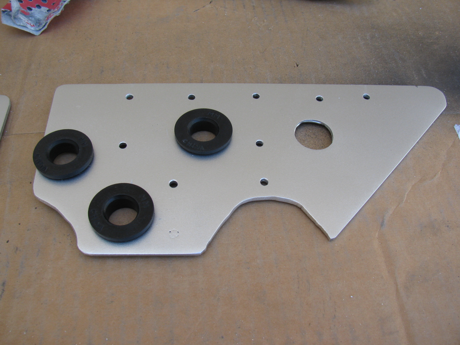
Since the 1/8-inch aluminum plate I am using for these brackets is scrap material, some extra holes are sometimes included in the items I make. When I am not able to re-use existing holes, I patch them with JB Weld or epoxy, then paint the item with high temperature BBQ paint. These brackets are finished in silver.


The large holes are cushioned with a PCV grommet; it is thick and large enough to pass the 3/8-inch fuel lines nicely.
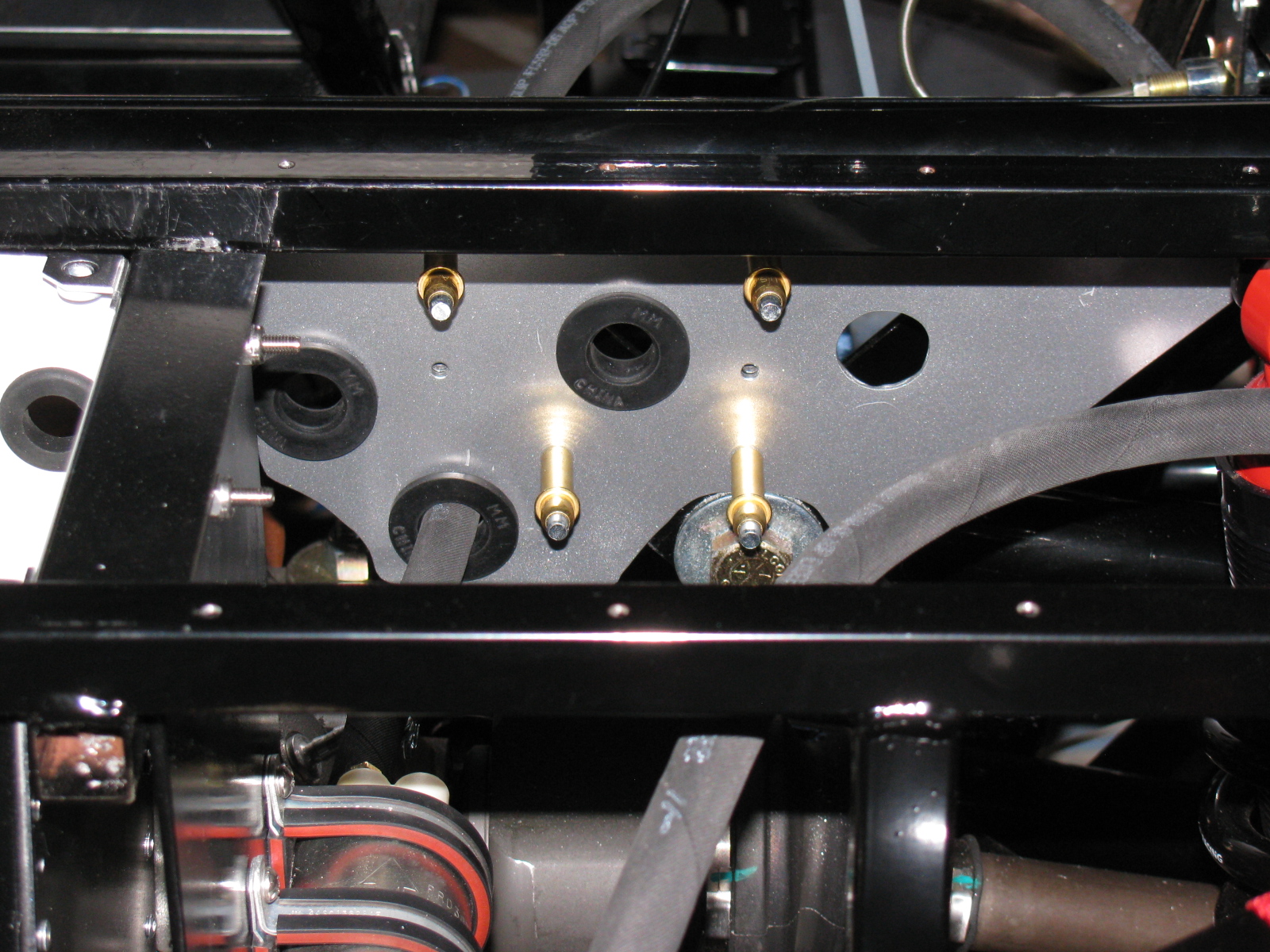
Here are some views of the passenger-side bracket installed with Clecos:


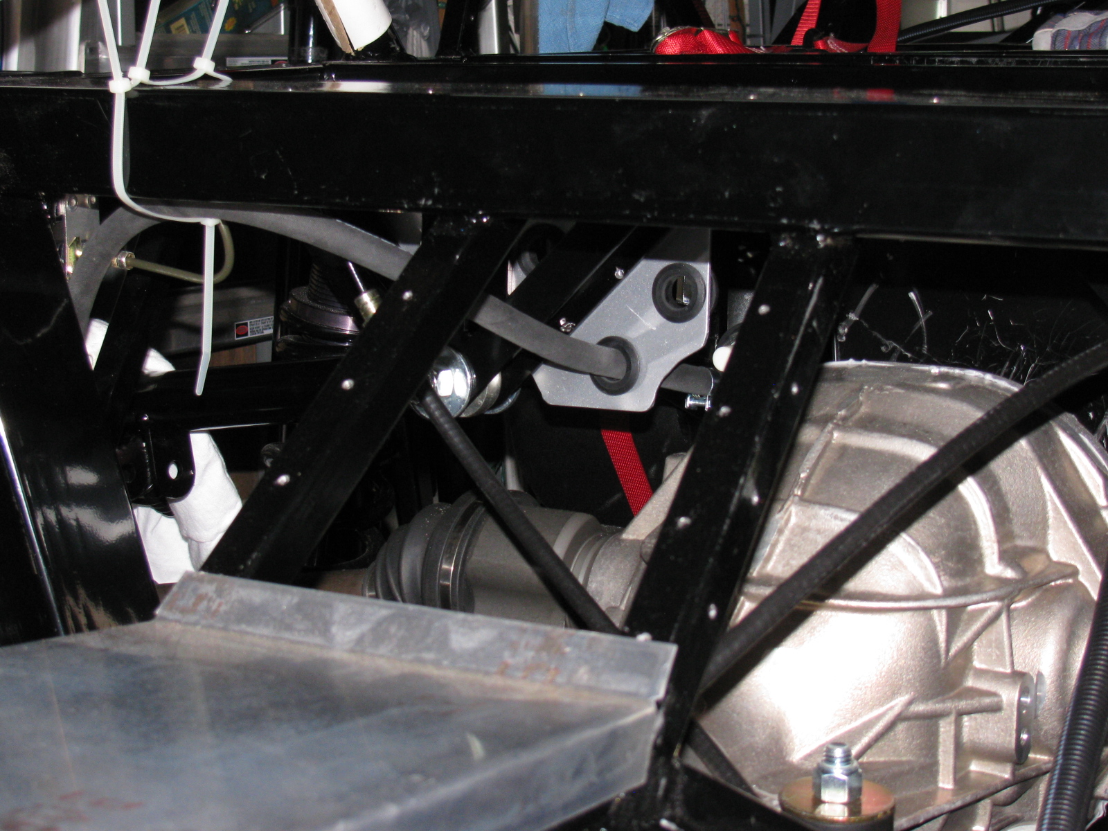
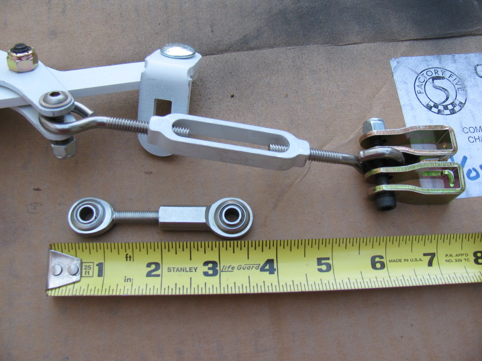
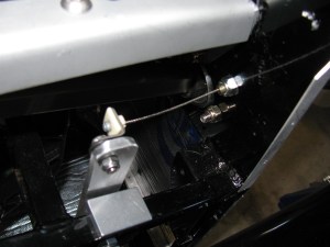
Next, I started laying out the e-brake cables and the complete kit e-brake handle. When I installed the rear brakes, I thought the cables looked too short. And last night I noticed that I am correct – the cables supplied with the IRS brake kit are about four to six inches too short.
I may have a solution to this, based on some Forum postings on this same topic — see the photo below. I do not like the turn buckle from the hardware store, I think I should replace it with a stainless steel clevis six to eight inches long to allow for adjustment. (McMaster-Carr items. . . )

UPDATE: I ordered an e-brake kit from Richard Oben of North Race Cars. (The same place I ordered my air conditioner – yet to be installed). The kit will move the e-brake to a more practical location at the top of the transmission tunnel.
Many builders of the Roadster as well as the Coupe do not like the way the brake cables rub against the big four inch tube. I will make a small Teflon block and mount it to the bottom of the chassis so the cable can slide more easily, and make it look much nicer. More details when I get to that step.
Main Wire Harness
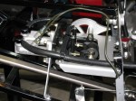
I started laying out the main wire harness. A few weeks ago, I painted the fuse panel with white appliance epoxy paint. This will brighten up the underside of the dash and will prevent corrosion. Based on something I read on the Roadster section of one of the F5R Forums, I added a small hinge to the fuse panel mounting plate. You can see the hinge on the right side of the bracket in this picture:

However, this is bad advice, at least for my Coupe application. This is not a good thing to do for several reasons:
1) It moves the fuse block about a quarter-inch forward into the footbox, and adds strain to several wires in the Ron Francis harness supplied with the Complete Kit.
2) The reason for the hinge was to make it possible to swing the entire panel down for easy servicing. However, this is impossible, since there is not enough slack and the thick harness will not allow the fuse panel to simply “swing down.”
3) The mounting holes must be very close to the edge of the 2-inch rail. Removing the hinge makes a better location for the mounting screws.
After removing the hinge, and mounting the fuse panel per the instructions, I noticed some “squishiness” in the fuse panel, which I do not like. I have not seen this mentioned in any post so I thought I would bring it up here.
The fuse panel is a piece of thin aluminum, laser cut to shape to hold the plastic fuse panel. Three zip screws (the self-tapping hex-head screws that held the cockpit aluminum in place when the kit was shipped) fasten it in place under the driver footbox, near the steering column.
All fine and dandy, but the fourth corner is “floating in space” and flexes easily. I decided to add a small aluminum bracket to make the fuse panel stronger (flex less). I hope the bracket does not get in the way of anything to be mounted later….


After several weeks, it is good to get back to work on the Factory Five Racing Type 65 Coupe. I finally completed drilling the rivet holes for all cockpit aluminum panels, and added a battery cut-off switch as you can see above.
Here is a hint for builders – there is a fairly large gap in the bottom right corner of the driver’s side floor and the “A” shaped piece that meets the transmission tunnel. I looked at several Coupes and Roadsters and they all have this space. However, by pushing on the A-shaped piece from behind (under the chassis and in the engine bay) – this gap can be closed up nicely. See below. . .


But what about this area, at the rear of the driver’s side door – indicated by a piece of blue masking tape – see that gap? Does something cover this space up or do I need to fabricate a replacement panel? Both sides look the same.

As mentioned in a previous post, I finally decided to mount the external fuel pump under the Factory Five Metal battery box. This is a protected location and is a low point on the chassis.

One problem will be access to the fill and drain holes for the Ford Racing differential. I had to drill out the rivets previously installed and tapped some 1/4-20 holes – this will enable the removal of the battery box when draining and filling the rear end fluid. Not the ideal situation, but I do not see too many alternatives to this arrangement.
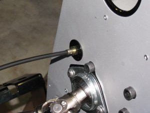
My Ford 302 V8 has an MSD Atomic electronic fuel injection system, and I am running both feed and return fuel lines. Here is a picture of the tank end. . .

The fuel line runs from the first filter (right side of the chassis) to the fuel pump, and goes around to the driver side. Then it goes under the rear end to the passenger side of the chassis, where it goes to a second fuel filter mounted under the passenger seat, and finally to the engine.
The same path will be used for the return system. Pretty much standard layout.
Next Build Session
Depending on the weather, I will remove all interior panels and paint the under side with automotive under body paint. It is a rubberized black paint which should deaden some road noise, insulate heat and protect the panels from road debris.
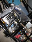
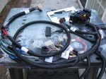
Another item on the next to do list is the wiring harness. Here is a look at the main portion. . .

It’s been a long time since I posted an update on the Factory Five Racing Coupe. Here is an update in pictures and captions . . .
-
-
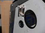
Type 65 Coupe complete kit brake reservoir bracket location
-
-
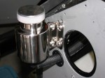
Polished stainless steel brake reservoir can, Type 65 Coupe, Complete Kit
-

-
I added a plastic grommet from the hardware store electrical section to prevent chafing the brake fluid hose.
-
-
I followed the hose layout as shown in the current Roadster build manual.
-
-
I used a big socket (35mm, I think) in a bench vise to bend my brake lines. Nothing fancy.
-

-
Brake lines are bent into rough shape, then taped in place along its route. Final bending is done on the chassis by hand.
-

-
Brake line held in place with tape, More adjustments are done by hand. Notice the way the excess lines are curved – this allows flexing in two planes – up and down and left and right. This is a 40-inch, pre-flared line I bought at a local car parts store. The supplied 60-inch line was way too long.
-

-
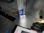
I start my brake line layout by marking the center of the span. This is the large rectangular tube going across the rear. The white wire (number 12 solid copper house wire) is used to make an extremely rough approximation of how the line will run.
-

-
Here you can see the white wire mock-up next to the steel brake line. The roughly Ohmega shape is centered above the IRS pumpkin.
-

-
I decided to run the rear brake line on the inside of the firewall. It will look cleaner in the engine bay and will help keep the line cooler.
-
-
I got lucky. I used a 60-inch line from the rear master cylinder, down the inside of the firewall, and ended up under the driver seat area. A second 60-inch line goes from the union to the rear brake tee. No custom length needed.
-
-
Here’s how the line goes up the support next to the lower rear sway arm. It will be slightly bent away from the chassis and held in place with the insulated line clips to prevent chafing.
-

-
Going up to meet the rear brake flex line, driver’s side.
-
-
A peek into the pedal box – I am still not quite sure how this is going to work. The sheet metal on the right is going to be covered by the Coupe body, so this will be riveted – or screwed – into place. The open side on the left is going to have a one-piece cover. Will this provide enough access for brake balance and clutch cable adjustments?
-

-
Inside the pedal box, showing the front brake line going to the master cylinder. Not as pretty as some others I have seen, but I can always re-do this later, right?
-
-
Here is a view of the rear brake line going to the second master cylinder. I drilled out one rivet fastening the sheet aluminum to the firewall and replaced it with an 8-32 stainless steel screw. It holds the line clip as well as the firewall panel.
-
-
Next on the to-do list: Wiring
-

-
Next on the to-do list: Fuel tank.
. . . and a BBQ Dessert Experiment
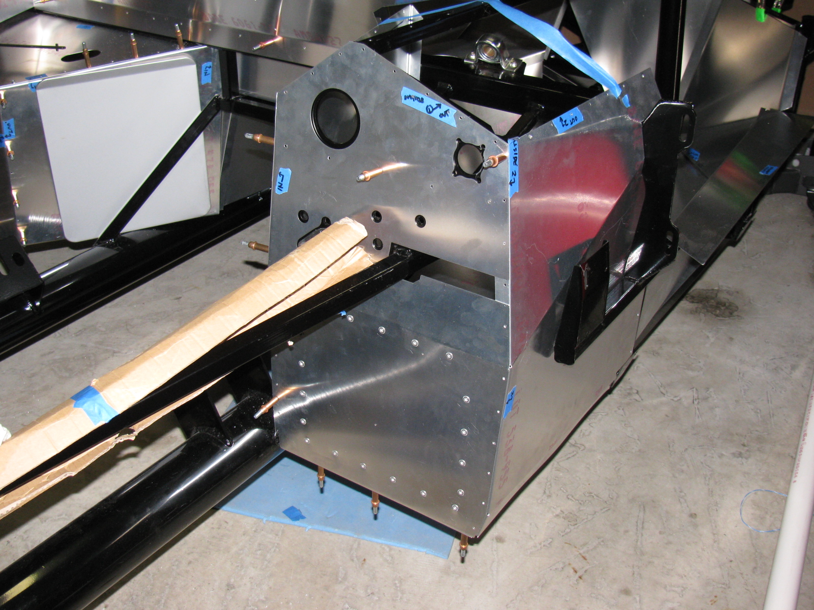
Work on the passenger and driver side foot boxes continues on the Factory Five Racing Type 65 Coupe.
I painted the engine side of the panels with silver BBQ paint, and left the interior side un-painted, since all panels will be covered with Cool-It heat and sound barrier. Panels that face the exterior of the car – like the foot box floors and the trunk area, will be painted with RustOleum truck bed liner. It is a textured black finish that will also help reduce sound and noise. Here are some images. ..


On the left is a detail of one of the cookie sheet heat shields, fastened to the firewall with 8-32 riv-nuts. The spacing is about one-quarter-inch. On the right is a view of the top of the heat shield, showing the nicely rolled edge.


Passenger side foot box appears on the left of the photo above. The photo on the right shows a closer look at the passenger foot box.


Photos above: Passenger foot box, before and after installing the Cool-It mats.


Above left: The top seam on the passenger foot box – this will be either trimmed or a strip of aluminum will be used to cover the mis-match. On the right, I added srtips of aluminum angle to the outer wall of the driver side foor box. This should make the outer wall easier to install.
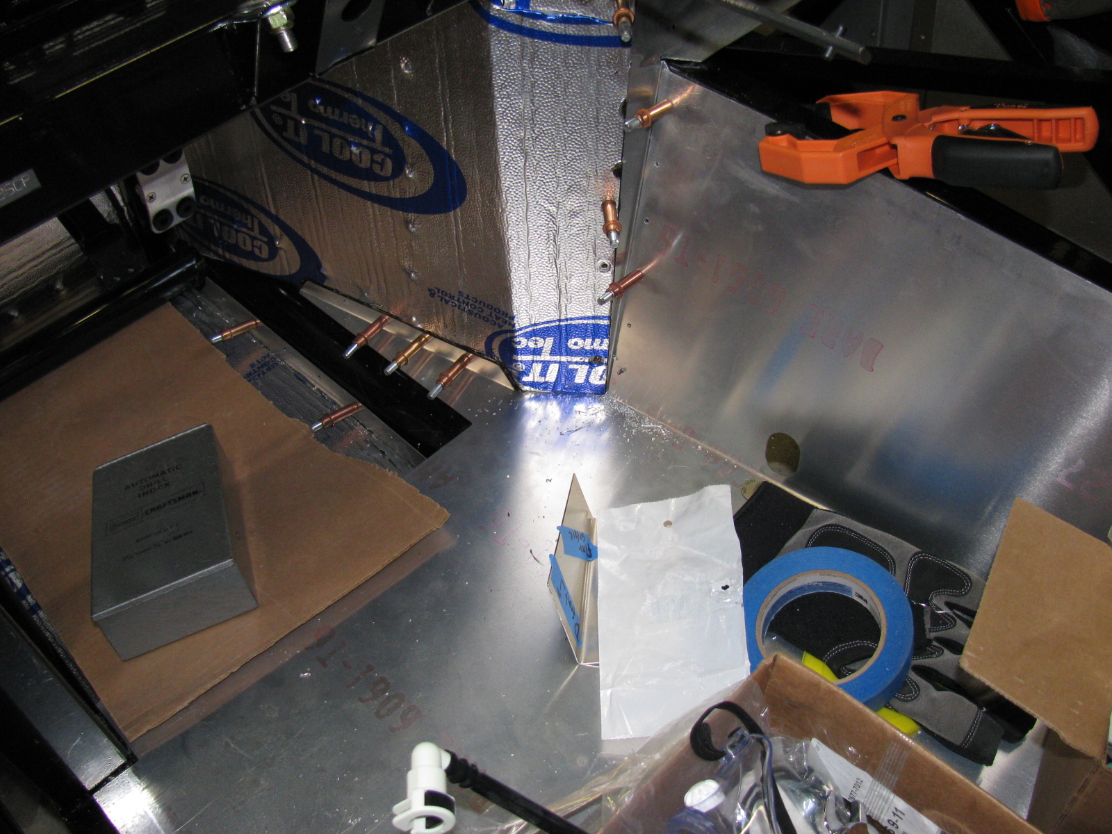
The next series of photos show how the interior panels go into place. The un-finished aluminum is difficult to photograph, I wish the manual would include an exploded view of the panels and how they fit into place. This is a complex jigsaw puzzle, and many of the parts must be flexed, trimmed and pulled into place. Clecos really help. This is one area where the manual offers good advice – the sections fit best when you follow the order outlined in the manual. Although many of the panels are marked with a part number, they do not indicate the orientation of the panel.
The foot box floors were very difficult to fit into place, so I sliced them into sections. If you look carefully you can see the saw kerfs (seams) on the floor panels. I chose the cuts carefully, in order to make sure I would have something solid to rivet to. In the areas without any supporting chassis tubes, I will install strips of aluminum bar stock.
The panels will be permanently attached later with silicone adhesive and rivets – at this stage, the panels are being “dry-fitted” with clecos to make sure everything is properly in place.


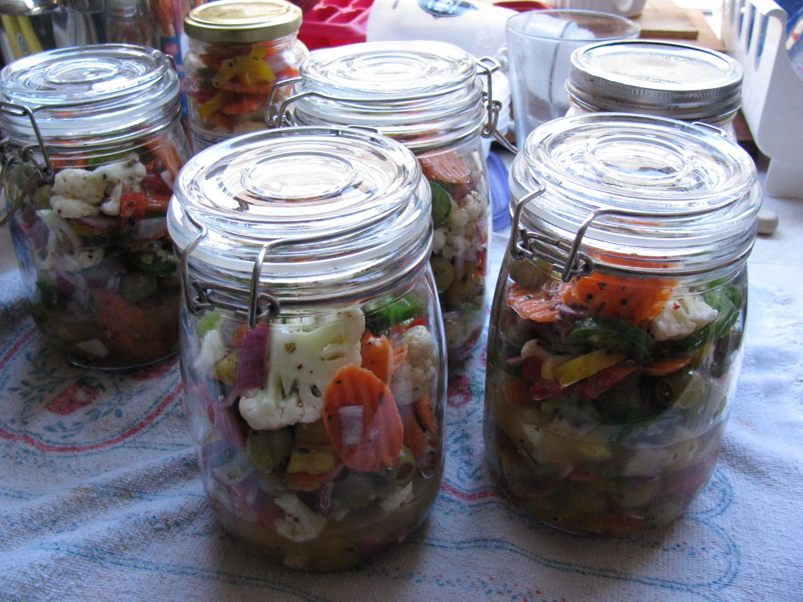
Somewhere during this building session, I made some time to pack my hot giardiniera into jars, and made a few deliveries. . .
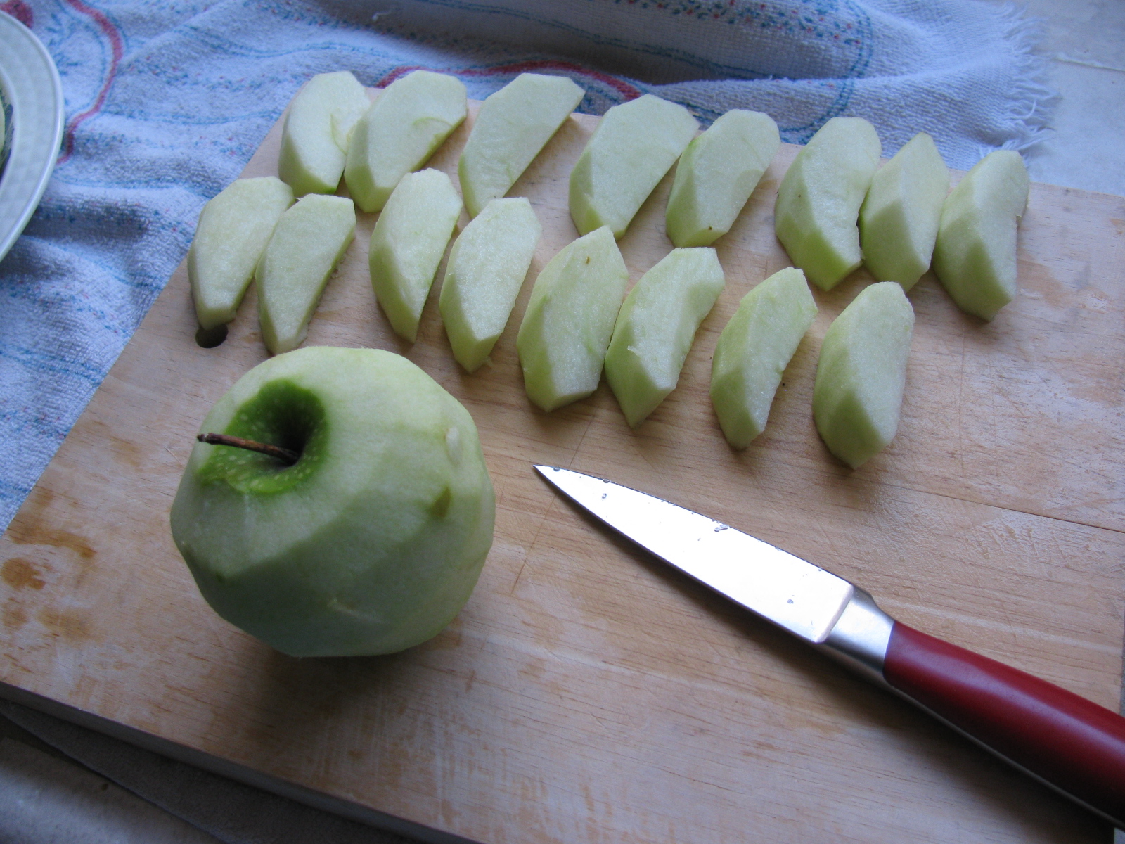
I also managed to do some BBQ experiments. This time I baked some apple turn-overs in the Big Green Egg. They turned out OK, but could be better. They are like just-right bites of apple pie. Here are some pictures. . .


It’s been a few weeks since I posted an update. Some people have been asking for some news, so here we go. . .
I am preparing the chassis so I can install the engine and transmission. This means that I have to finish the firewall, which means prepping and painting the foot boxes and routing and mounting the brake and fuel lines.
I decided to finish the engine bay with silver Rust-Oleum high temperature BBQ paint. This is a change from my thoughts on powder coating and appliance epoxy. . . The appliance epoxy has an upper temperature limit of 200 degrees F, and I think engine bay heat is higher than an oven. The BBQ paint is good for 1200 degrees F or something like that. Depending on how the engine bay looks, I may strip everything off and re-finish with powder coat later. But for now, the silver BBQ paint looks OK. The nice weather last week allowed me to do some rattle-can spraying outside.
I permanently mounted my first aluminum panel – the driver’s side foot box front. I am using Permatex Ultra Black number 2105 silicone adhesive. This is what Kirkham Motors uses for their builds, so I will use what they use. It can be used as an adhesive as well as a gasket, so this extends its usefulness around the shop.
References: Kirkham online build and Permatex Ultra Black goop


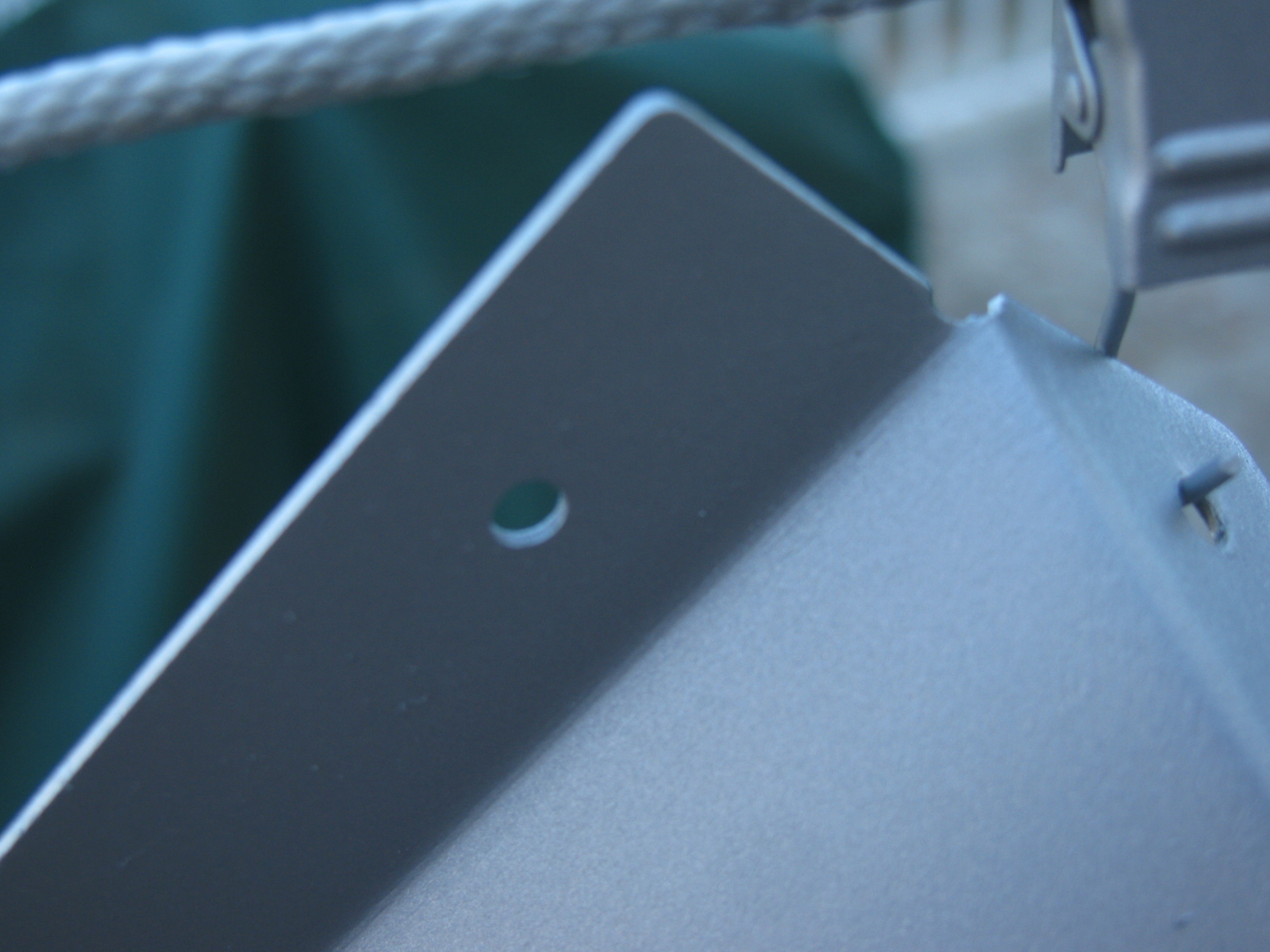
Above right is a close-up of the BBQ paint finish on one of the pedal box panels. Looks OK. There is a slight texture to the finish. The color is actually silver, the blue-ish tint is probably from sunlight diffracting from somewhere.

Above left, a “dry fit” of the driver side foot box front panel. You can see the cookie sheet heat shields in place. Above right, using the panel as a pattern to cut the insulation mat – just place the panel onto the backing side of the mat, press down and then cut with shears or a knife. Final trimming is done with a utility knife.
Cool-It heat and sound insulation is applied to the interior side of the foot box panel. The “bubbles” you see are from the riv-nuts and screws poking out from the other side. On the right, I wanted to make sure the adhesive stuck properly at the top of the panel, so I used some clamps to squeeze evenly. My good friend Norm Abram always says, “You can never have too many clamps.”
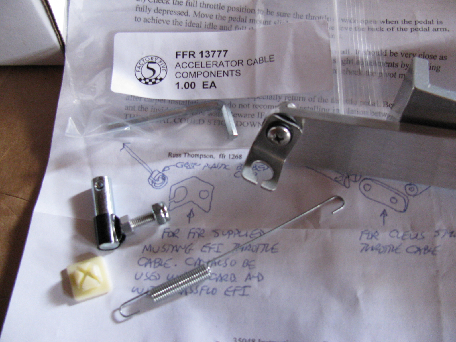
The Accelerator Cable and Pedal
I mounted the accelerator cable as well as the Russ Thompson gas pedal, sold by Breeze Automotive. The instructions are different from what is being supplied by Factory Five Racing now. (I am getting used to this. . . )

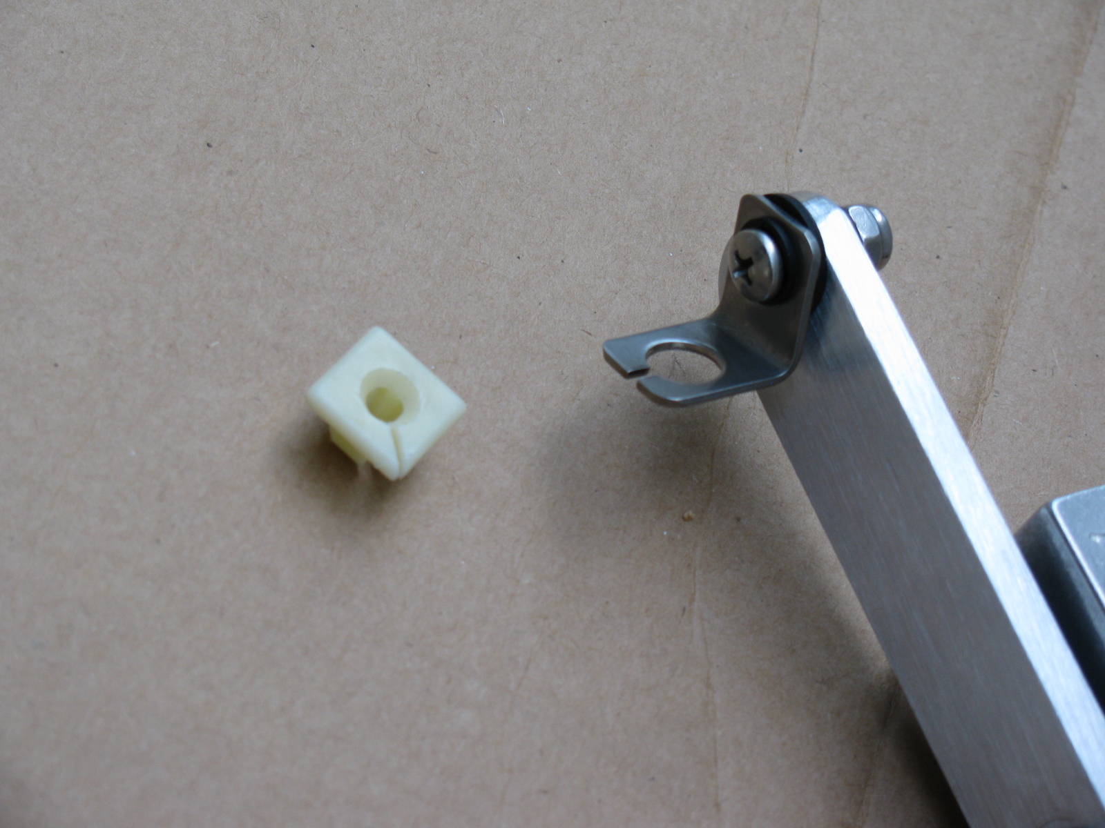
The picture above shows some of the gas pedal mounting parts that come with the Complete Kit. The Thompson / Breeze pedal instructions say something about a “green plastic barbed clip” at the end of the throttle cable. This green thing is no longer what comes with the kit. Instead, there is a little square “plug” that is too big to fit into the pedal mount.
Rather than cutting off the ball-end at the throttle cable or drill a bigger hole in the mount, I decided to carefully cut some of the plastic from the center barb so it would fit snugly into the mounting hole – not much has to be shaved off, it is something like a sixteenth of an inch or so. Then I made a slit in the square plastic thing as shown so the cable could slip in with the ball intact.


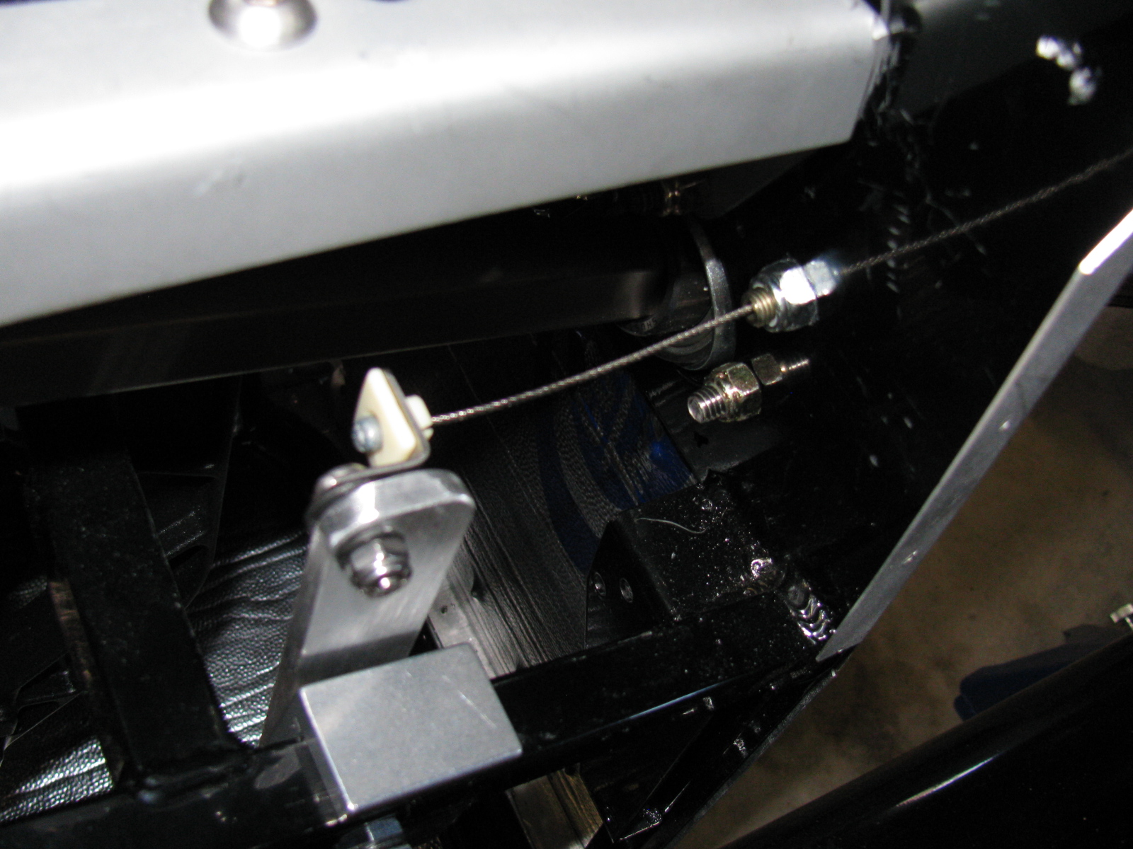
As you can see above, I added a fender washer (painted black) to the throttle cable mounting point, this is just for looks.
This is Irritating
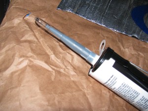
For some reason, this bothered me today, but then I realized not many tubes of caulk gun goop come with caps. Anyway, I used a pen cap to close the tube. I hope this works, I only needed a few beads for this build session.
Some Great Looking Door Panels on Order!
I ordered a set of leather door panels from Levy Racing earlier this week. They look like this:

Since the engine is in the middle of my garage, I really need to accelerate my building, or at least, get my chassis ready for engine installation.
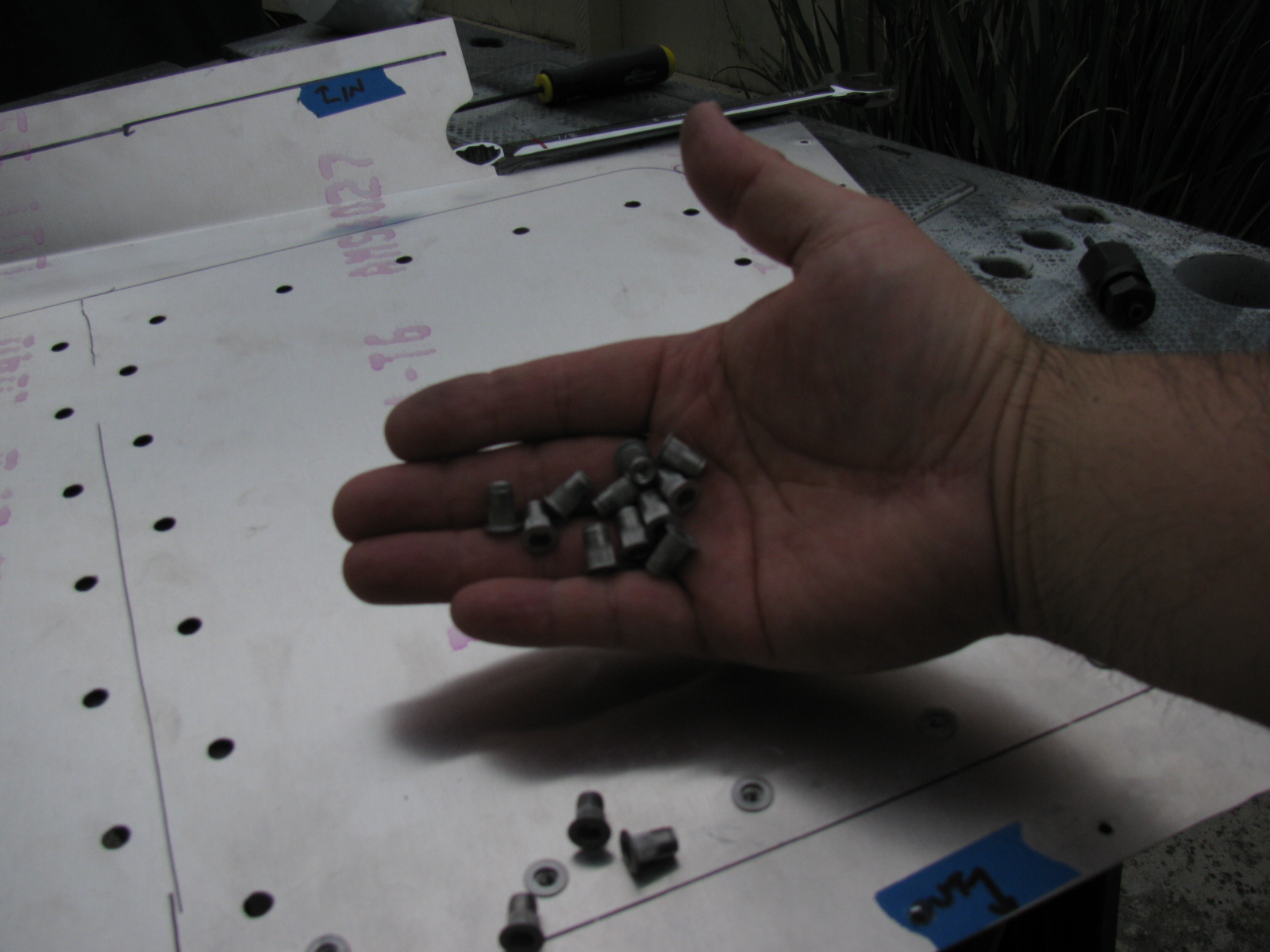
I looked at my cookie sheet heat shields and the mounting locations filled with 8-32 riv-nuts, and thought – shoot, the riv-nuts actually have a shaft that might be used as stand-offs for the shield plates. So I checked the length, and the threaded shafts are about a quarter-inch long, enough to be used as a spacer between the firewall and the heat shield. I may add another quarter-inch in certain places, if there is room.
So I spent a few hours removing all of the riv-nuts I installed a few weeks ago. Good thing I bought several hundred from McMaster-Carr. . . .
At least I am an expert on installing and extracting riv-nuts now.
Rivet Nuts and the Rivet Nut Tool
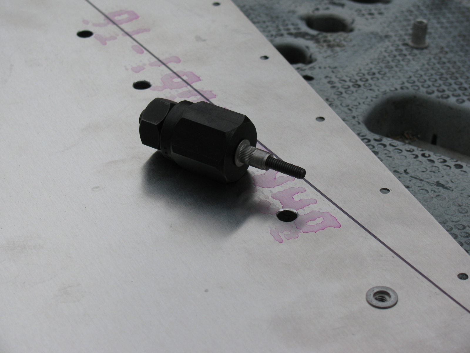
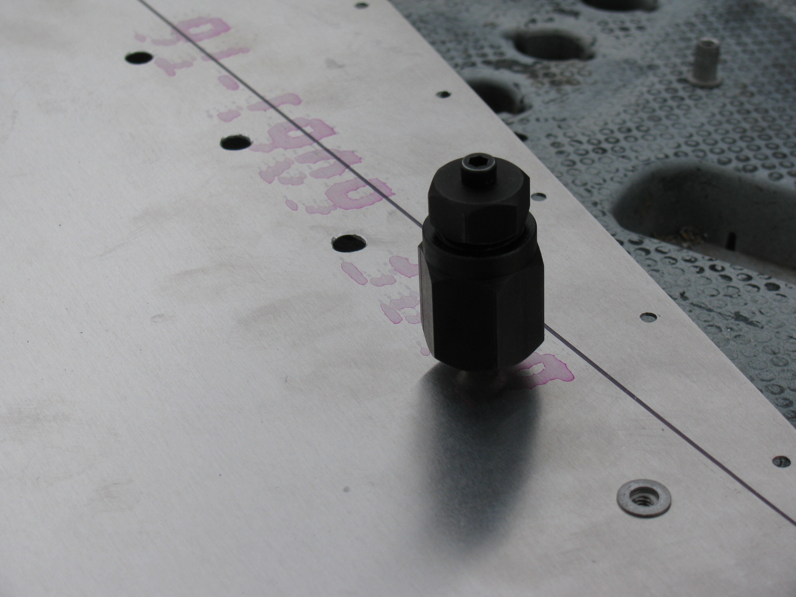
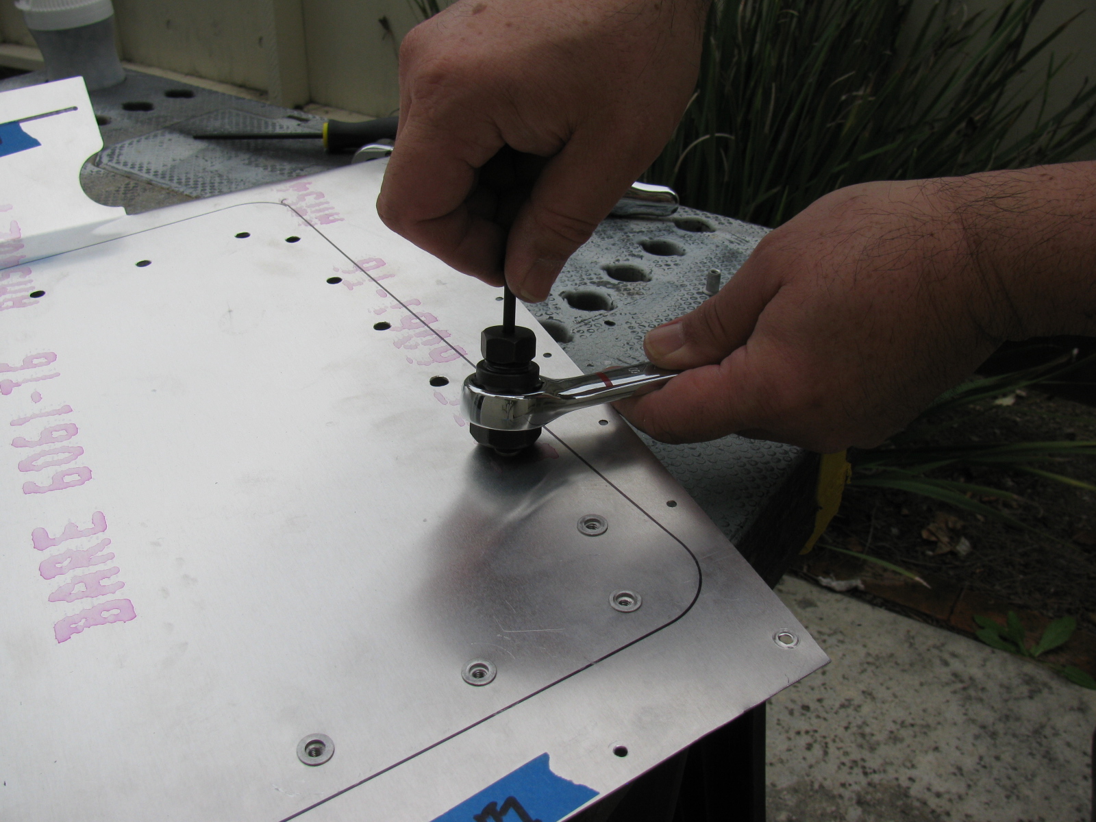
Here are some pictures of the riv-nut tool from McMaster-Carr and how it is used. Riv-nut fasteners are very handy if you need a threaded hole installed into a blind location, or when you do not have access to the back side of a mounting surface. I will use these fasteners for hatches and compartments in the trunk area of the Type 65 Coupe.
McMaster-Carr information
Wrench-drive rivet nut installation tool for 10-24 and 10-32 thread: 96349A203
Wrench-drive rivet nut installation tool for 8-32 thread: 96349A152
Wrench-drive rivet nut installation tool for 6-32 thread: 96349A101
Aluminum heavy-duty rivet nut, 6-32 internal thread, .080″-.130″ material thickness, packs of 25: 94020A315
Aluminum heavy-duty rivet nut, 8-32 internal thread, .080″-.130″ material thickness, packs of 25: 94020A323
Aluminum heavy-duty rivet nut, 8-32 internal thread, .020″-.080″ material thickness, packs of 25: 94020A319


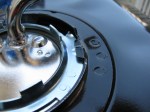
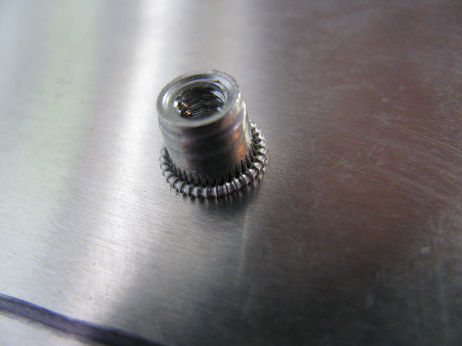
Above left – a picture of a properly installed riv-nut, viewed from the reverse (back) side. At right, a riv-nut improperly installed, viewed from the face (front) side. This one must be removed by drilling the riv-nut out. Below left, use a twist drill slightly smaller than the mounting hole, in this case, a 1/4-inch bit is being used to drill out the riv-nut. By slightly rocking the drill, the riv-nut will break apart and, usually, just fall out of its hole.


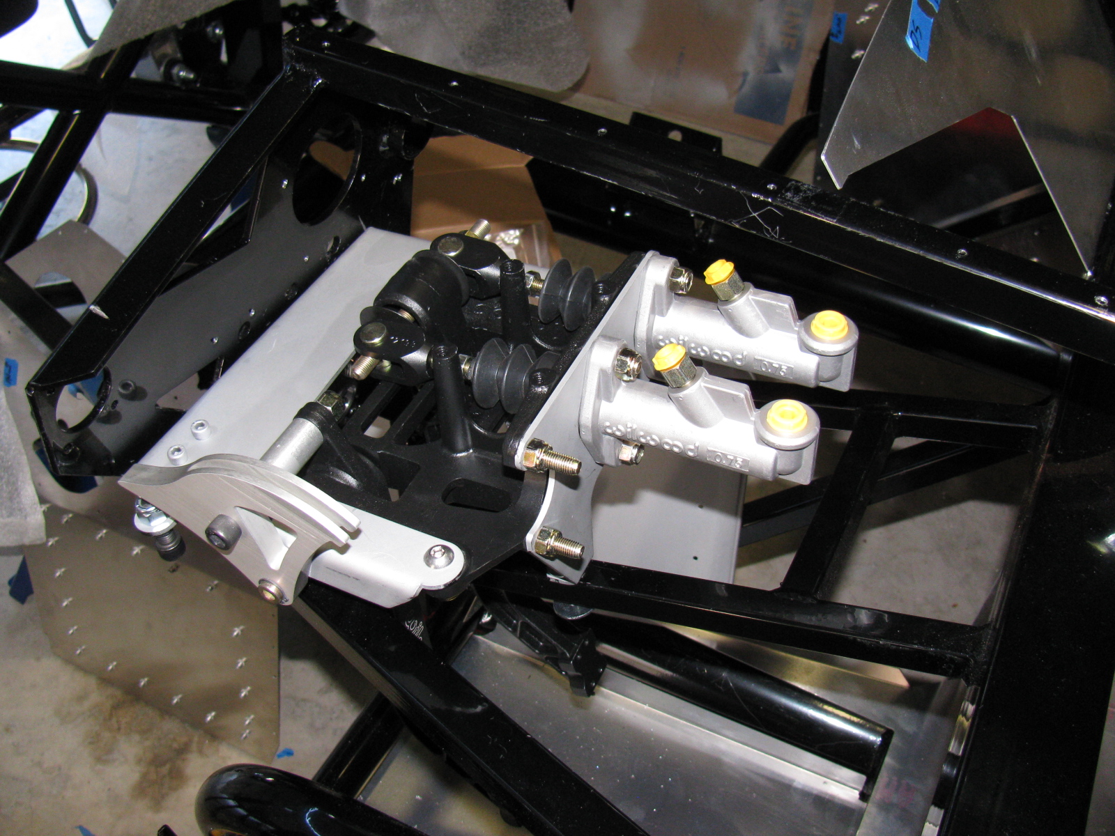
Give Me a Brake: The Wilwood Pedal Box
The pedal box is a challenge to install with the Factory Five Racing Assembly Manual, revision 3E, July 2011 – since there are no assembly instructions for the Wilwood Complete Kit pedal box.
Fortunately, a dedicated Type 65 Coupe builder named Chris has an excellent photo album of his Coupe build, with many detailed images. Without his documentation – it would have been impossible to assemble this part of the kit. Take a look at cbergquist1’s photostream on Flickr.
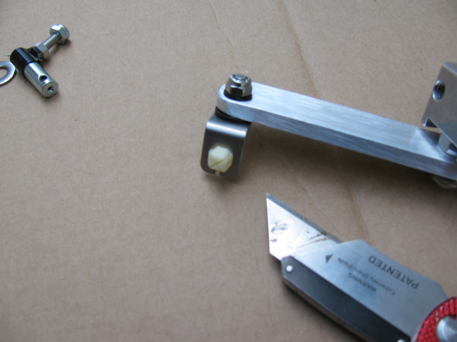
Here are some pictures of my pedal box, including a trouble spot I ran into, and how I had to fix it. . . .


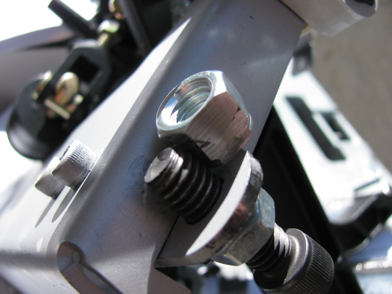
This is the clutch quadrant adjuster (above). This Nylok had to be ground down to fit properly. The hole in the adjuster plate is too close to the master cylinder mounting plate. A better solution would be to eliminate the Nylok altogether and thread the small plate. Then the lock nut and Allen bolt are used to make clutch travel adjustments.


Now I have to find a place to mount the master cylinder reservoir. There are some rare posts about this, but most of them are for the Factory Five Racing Roadster.
I think I will mount mine at or near the peak of the driver’s side footbox/firewall. This location should be away from too much heat, and should be in the clear for fluid bleeding, checks and re-filling. We will see. . .
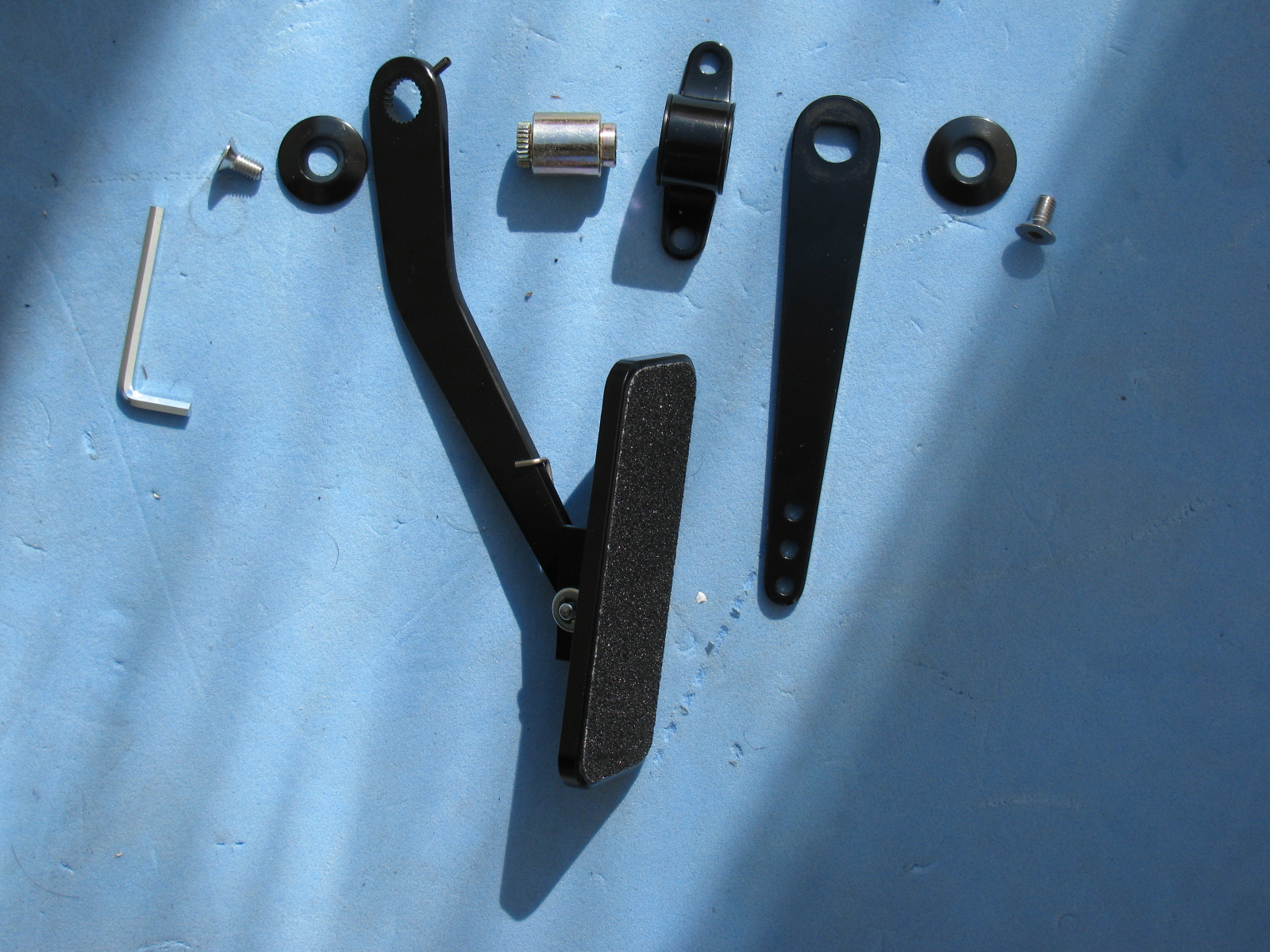
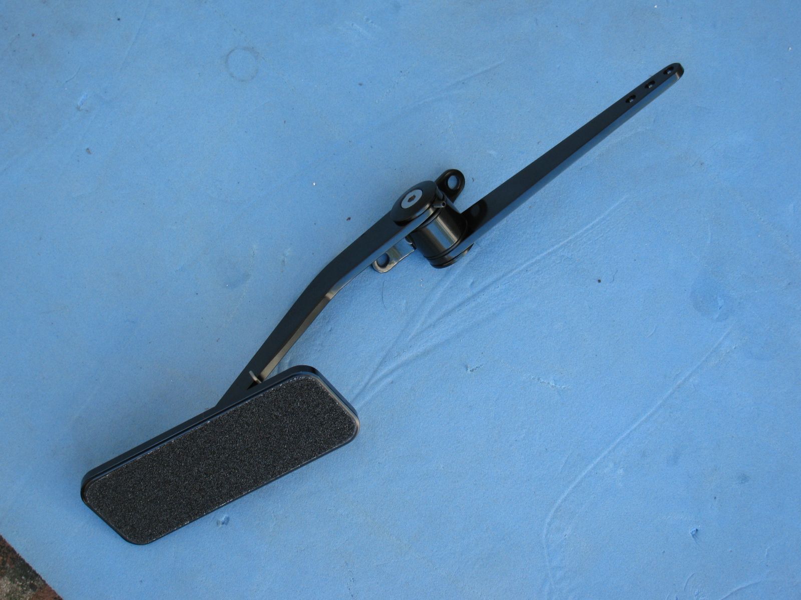
The Gas Pedal


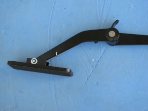

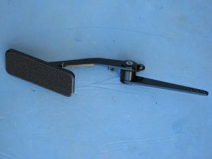
Part of the pedal box area is the accelerator pedal. Again, instructions are very skimpy on how to put this thing together. Here are some pictures of the gas pedal parts and how to dis-assemble the unit as it comes out of the box, and where it mounts onto the firewall area. Adjustments for the pedal box and accelerator pedal will happen later.
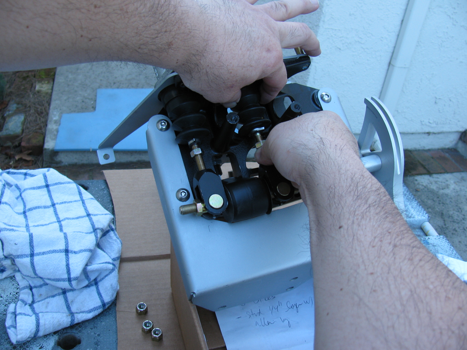
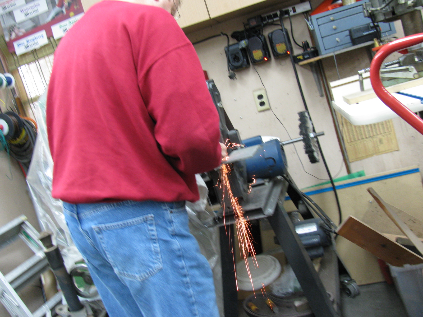
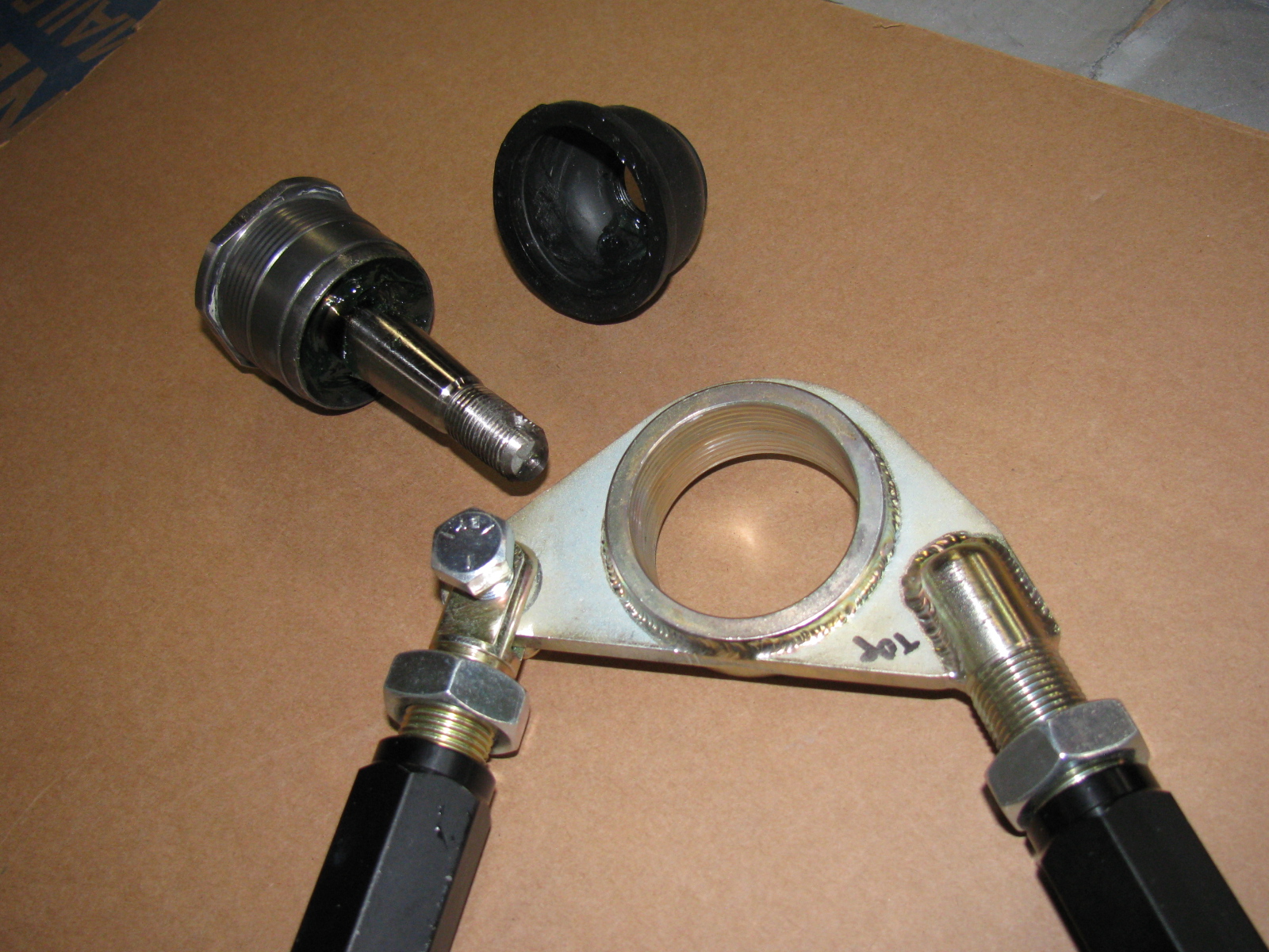
My go-to car builder friend Spider Larry once again came through for me. Using a Mapp gas torch and a piece of pipe, he separated the ball joint from the top mount for the passenger side suspension. Here are some pictures from the dis-assembly and re-assembly process on the Type 65 Coupe IFS, passenger side.


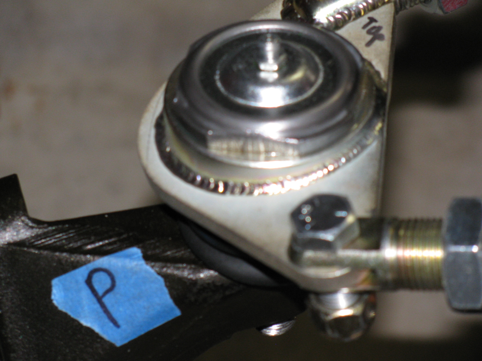
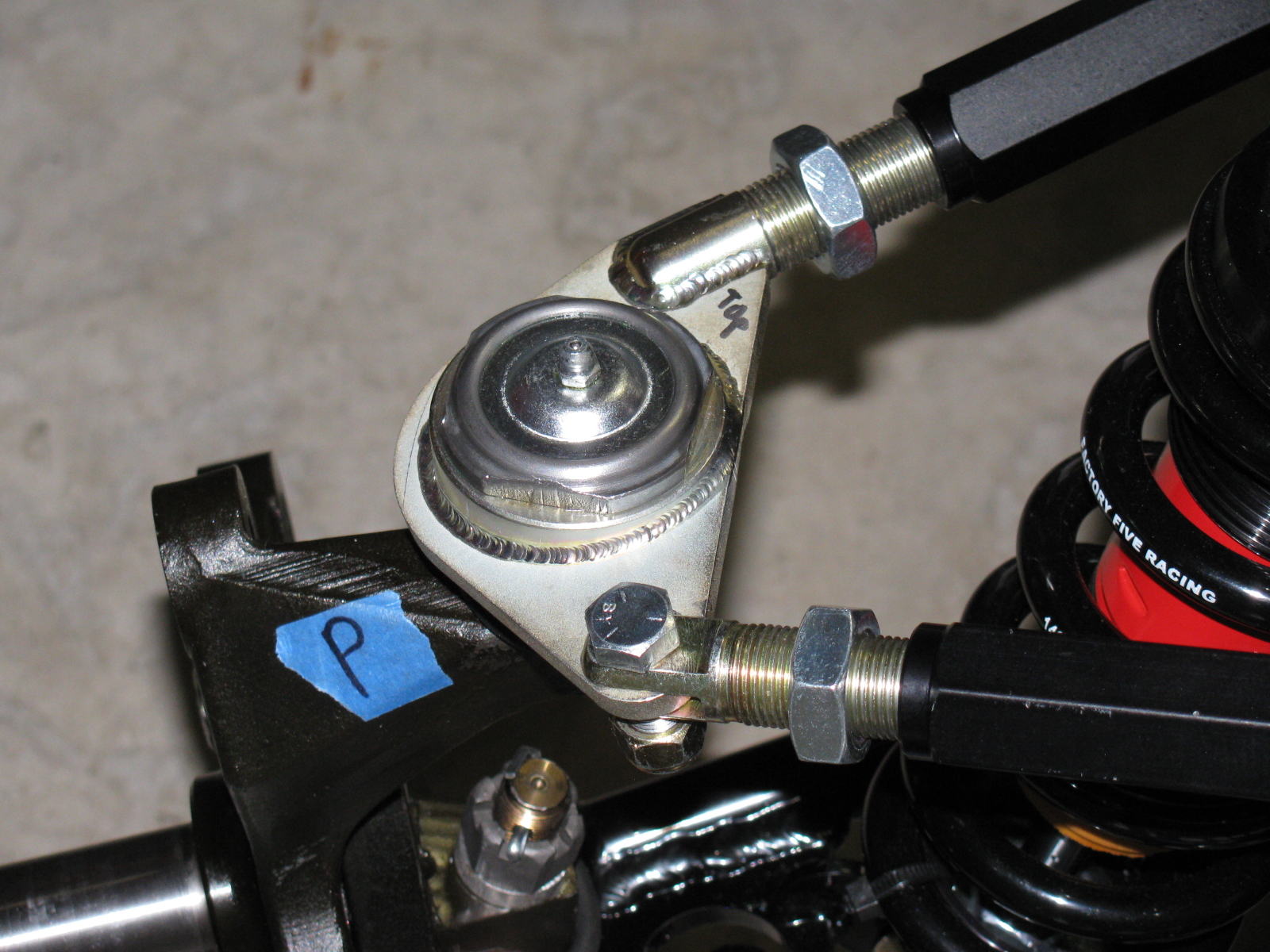
Here is the correct passenger side upper control arm and ball joint assembly:


The driver side looks like this:


So you MUST ignore the manual when it says to create a “left and a right unit with the ‘solid corner’ pointing to the front of the car.”
Footbox Heat Shields
I located, dry-fit, and drilled mounting holes for the driver and passenger footbox heatshields. The material is cookie sheet steel from the local grocery store. They have a nice rolled edge and will help deflect heat from the engine bay coming into the car interior. I am using riv-nuts and spacers to mount these sheets – er – heat shields to the footboxes.
I used BBQ paint for the shields, but may decide to powder coat the engine bay sheet metal parts, including the heat shields.
But I have to decide this quickly, since the engine is scheduled to be delivered within a few days!
Here’s the driver footbox with riv-nuts installed. All aluminum panels for the engine bay will be powder coated, the others will be painted.

Air Conditioning
Here is a picture of the air conditioner unit and where it will go. It fits behind the passenger side dashboard area, where a glovebox wold normally go. I need to allow space for the ducting and the windshield wiper mechanism, which mounts in the same area. A box to house the A/C unit will have to be fabricated.

The IRS – Independent Rear Suspension
Note to builders: This procedure is quite difficult, even with a helper or two. It is highly recommended to keep small children away to protect them from hearing rated-R and -X words and phrases loudly coming from the underside of the chassis and to keep them safe from thrown objects.
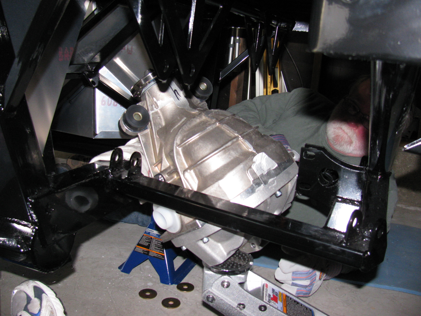
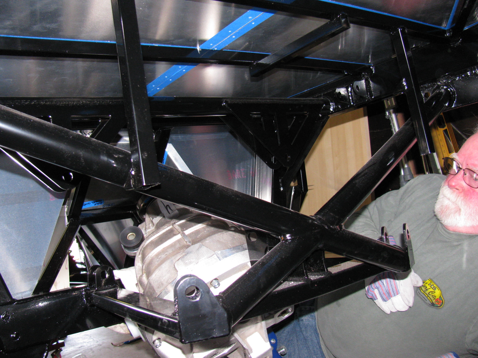
Since my ham radio friend Larry was going to stop by for a visit, I decided it would be a great time to get him to help me boost the rear differential (pumpkin) into the rear suspension cage. The Factory Five Racing assembly manual calls this unit the “IRS center section.”
There are many posts on how difficult this step is. The manual says, “It installs from the bottom with the driveshaft flange pointing straight up and the axle holes lined up front to back with the chassis.”
Err. So that means the giant 70 pound, lop-sided bowling ball like thing must be pushed up sideways, 90 degrees from the way it mounts onto the frame, and then must be twisted 90 degrees in the opposite direction to drop into place. This cannot be done safely with just one person. I found out that this is actually impossible to do with two people.
After several long hours and a phone call to Spider Larry, the pumpkin still refused to go into place.
I began to think about getting a grinder and removing any offending protrusions on the differential case and chassis to make this thing fit. My ham friend Larry had to leave, but a neighbor showed up, who also happened to be a car builder. I put Phil to work right away…
We tried a different route, maybe through the X-member at the rear of the chassis could work. So we used the jack to lift the differential high enough to check. We made a few measurements. No way.
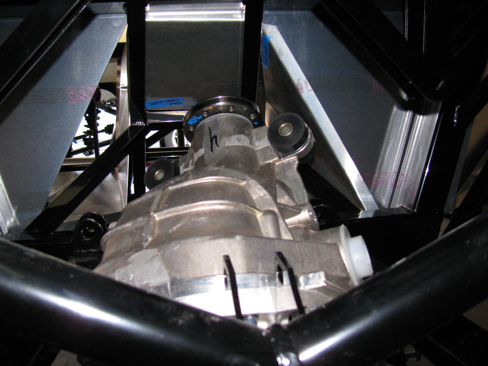
We measured again, and noticed that no matter how you turn this pumpkin, it will not fit past the rear cover mounting plates.
We decided to remove the rear cover.
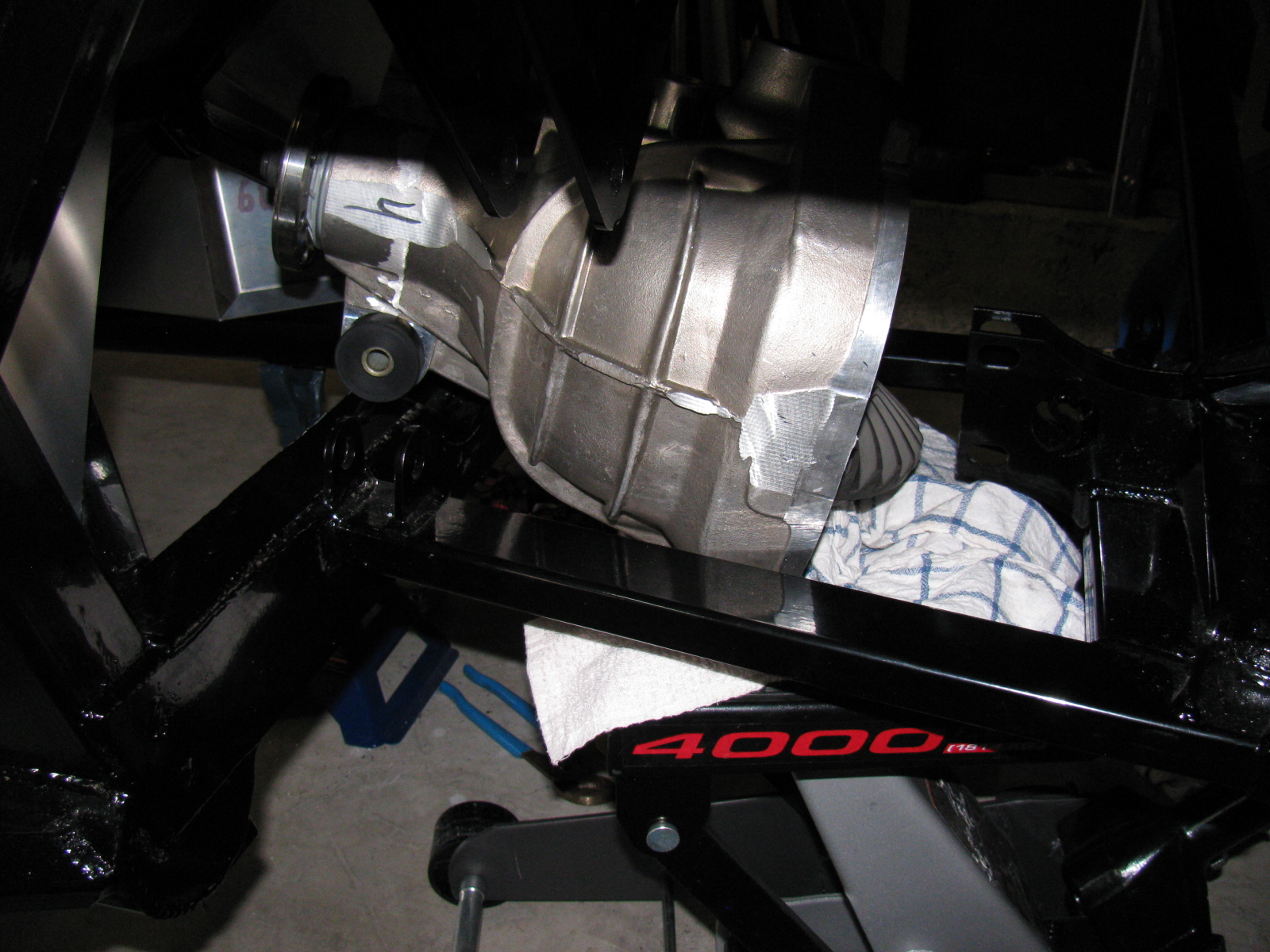
After unscrewing ten Allen bolts, and giving the rear cover a light tap with a rubber mallet, the cover popped off, very much like breaking an egg. To gain another inch of clearance, we removed the two plastic dust caps from the axle holes. Verifying that the diff does NOT have to come apart to mount the rear brakes, we put it back on the jack. Modifying the instructions, we lifted it with the driveshaft flange pointing up and the axle holes at a 45 degree (not 90 degree) angle, and pumped the jack. Now it went past the offending rear mounting plates, and into place.
Of course, now the differential must be re-sealed, so we tried a dry run with the rear cover. Yes, this will work. I currently have the pumpkin suspended above the mounting location, held in place with the jack, a 2×4, and a nylon strap. I will finish mounting this beast at the next build session.
Here are lots of pictures of the wrong way to do this. A video of this procedure would be most helpful, but I am sure most builders will have enough in their hands to not have a camera operator getting in the way.


So – take my advice, save at least 6 hours and lots of non-child-approved words and thrown objects, and remove the differential rear cover before you install your IRS center section. . . .


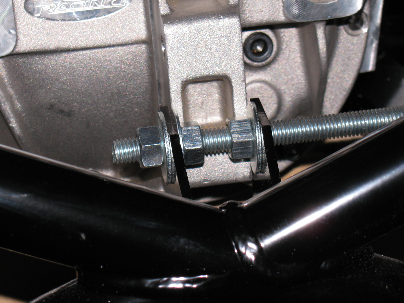
The rear mounting tabs (with the nice “5” logo laser-cut into them) are too close – use the threaded rod-expander trick to make it fit.
By the way – anyone else missing two nuts and bolts for the pumpkin mount? My parts list is correct, and yet I am still missing two fasteners for the standard width IRS differential.

I discovered I have the wrong adapter plates for the rear disc brakes, These are for the non-IRS version of the car. Jason at The Factory is sending the correct parts to me……