Archive for the ‘IFS’ Tag
It has been raining off and on all week, and continued through this past weekend. This is a good thing, since I can avoid yard work, and even better – I can spend more time in the garage. However, the garage has been cold, 40 degrees F. This pretty much kills any plans for painting anything.
Since the 80 pound metal medicine ball – also known as the pumpkin, center section, differential and other names – is re-sealed and mounted, the rest of the independent rear suspension assembly is going smoothly.
Learning something from the front suspension experience, I decided to assemble all the pieces on one side of the car first, and only hand-tighten the fasteners. This will prevent time-consuming error-fixing.
There is a saying on the Factory Five Forums – it goes something like, “if there aren’t any pictures, it didn’t happen.”
So, since there aren’t any pictures of the parts I installed backwards, it didn’t happen, right?
Let’s just say the assembly manual lacks good pictures to help us understand how to orient things properly. Many of the pictures are cropped too tightly, and do not show the nearby parts to help us visualize relationships to other parts or reference points.
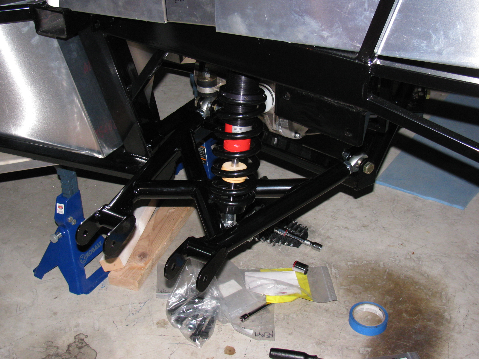
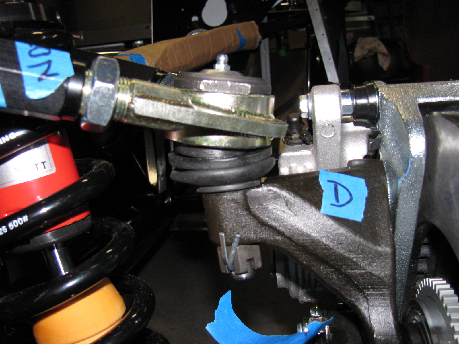
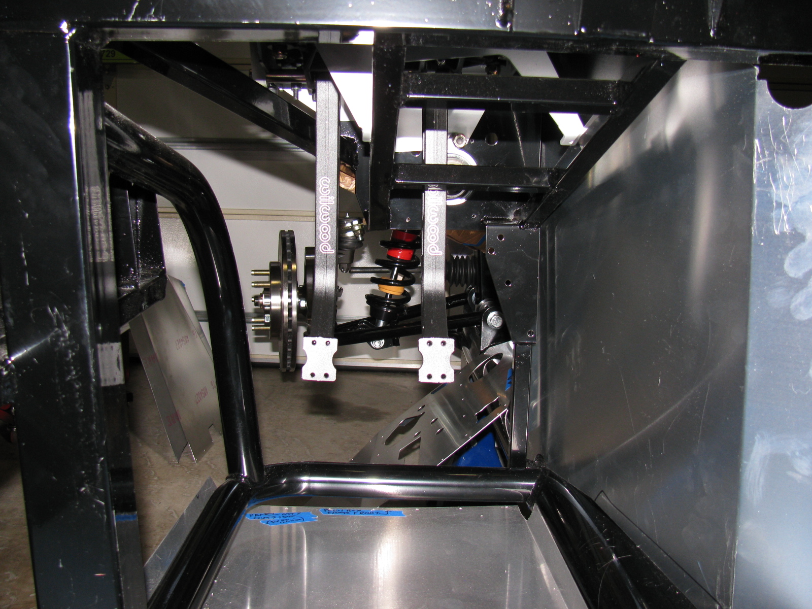
Here are some pictures of the driver side lower control arm and coil-over-shock being installed. . .


While mounting the lower control arms, I kept dropping a stack of small shims (they look like thin washers) needed between the chassis mounting tabs. Of course, since they are round, they roll all over and under the strangest places. I had to use a small magnet to retrieve several of them.
The magnet made me think of a great way to hold and install these small shims on the mounts. Take a look. . .

The little magnet holds the stack of shims together, and by wiggling, pushing and pulling on the suspension parts, the bolt will slide through the stack. This works great, and it makes me feel happy rather than mad while underneath the chassis.
Of course, this only works if the parts are ferrous. The aluminum spacers are another story.
The spindles, upper control arms, and CV axles are next. Stay tuned . . . .
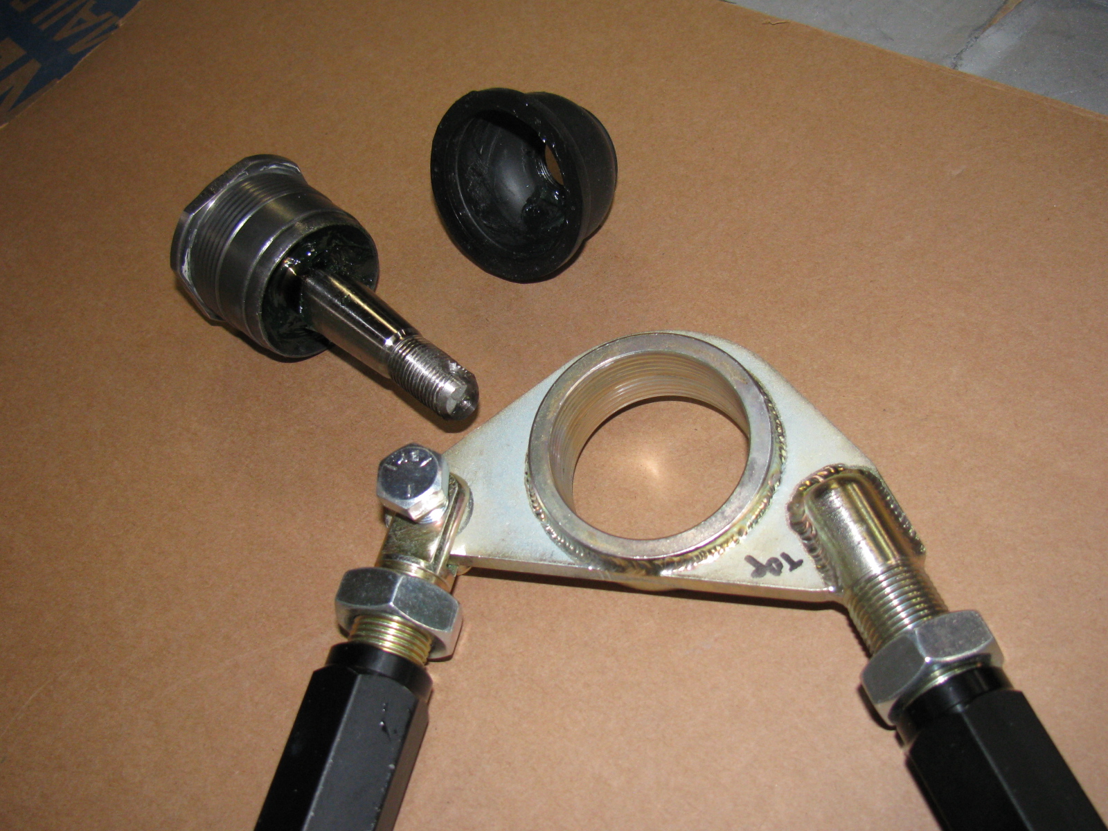
My go-to car builder friend Spider Larry once again came through for me. Using a Mapp gas torch and a piece of pipe, he separated the ball joint from the top mount for the passenger side suspension. Here are some pictures from the dis-assembly and re-assembly process on the Type 65 Coupe IFS, passenger side.


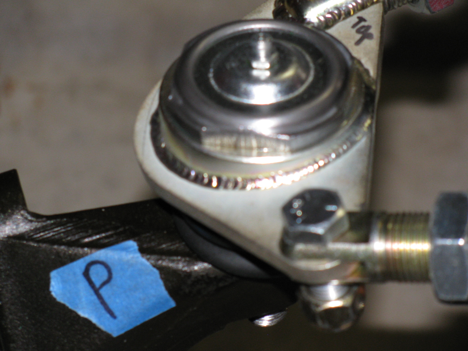
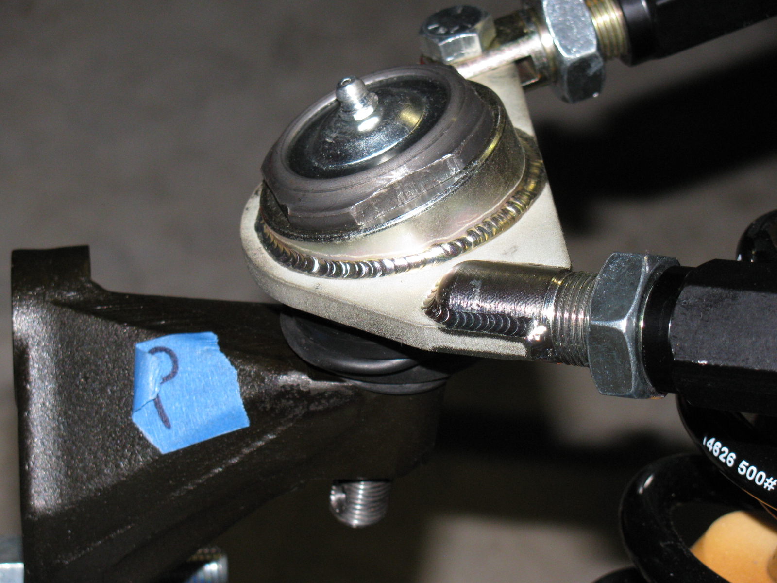
Here is the correct passenger side upper control arm and ball joint assembly:


The driver side looks like this:


So you MUST ignore the manual when it says to create a “left and a right unit with the ‘solid corner’ pointing to the front of the car.”
Footbox Heat Shields
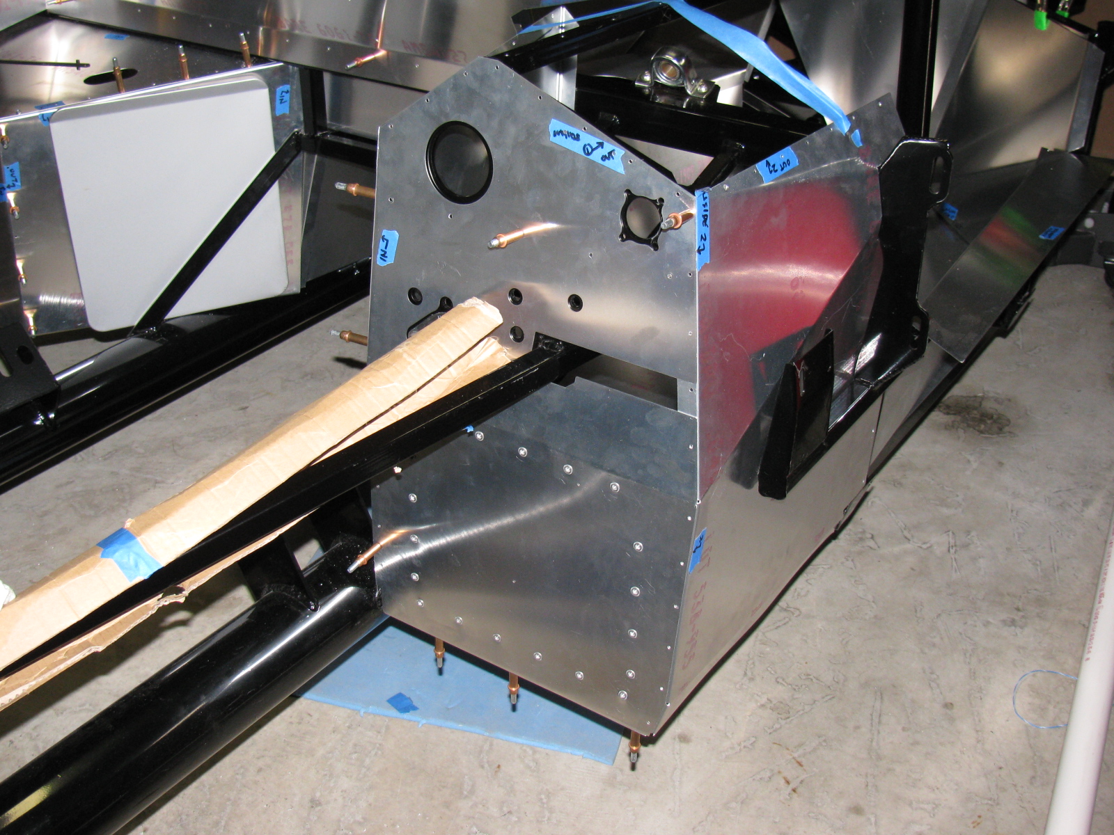
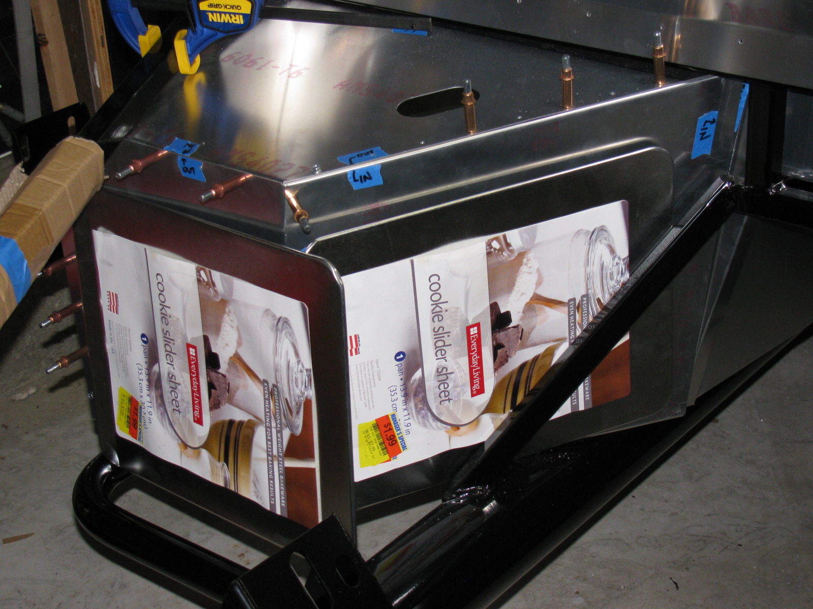
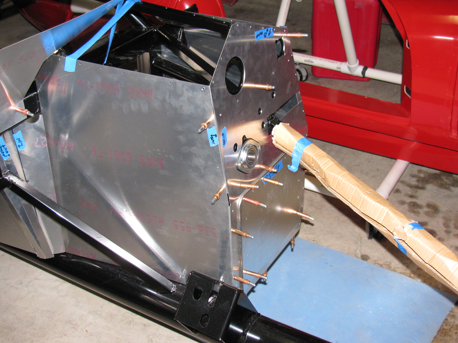
I located, dry-fit, and drilled mounting holes for the driver and passenger footbox heatshields. The material is cookie sheet steel from the local grocery store. They have a nice rolled edge and will help deflect heat from the engine bay coming into the car interior. I am using riv-nuts and spacers to mount these sheets – er – heat shields to the footboxes.
I used BBQ paint for the shields, but may decide to powder coat the engine bay sheet metal parts, including the heat shields.
But I have to decide this quickly, since the engine is scheduled to be delivered within a few days!
Here’s the driver footbox with riv-nuts installed. All aluminum panels for the engine bay will be powder coated, the others will be painted.

Air Conditioning
Here is a picture of the air conditioner unit and where it will go. It fits behind the passenger side dashboard area, where a glovebox wold normally go. I need to allow space for the ducting and the windshield wiper mechanism, which mounts in the same area. A box to house the A/C unit will have to be fabricated.

The IRS – Independent Rear Suspension
Note to builders: This procedure is quite difficult, even with a helper or two. It is highly recommended to keep small children away to protect them from hearing rated-R and -X words and phrases loudly coming from the underside of the chassis and to keep them safe from thrown objects.
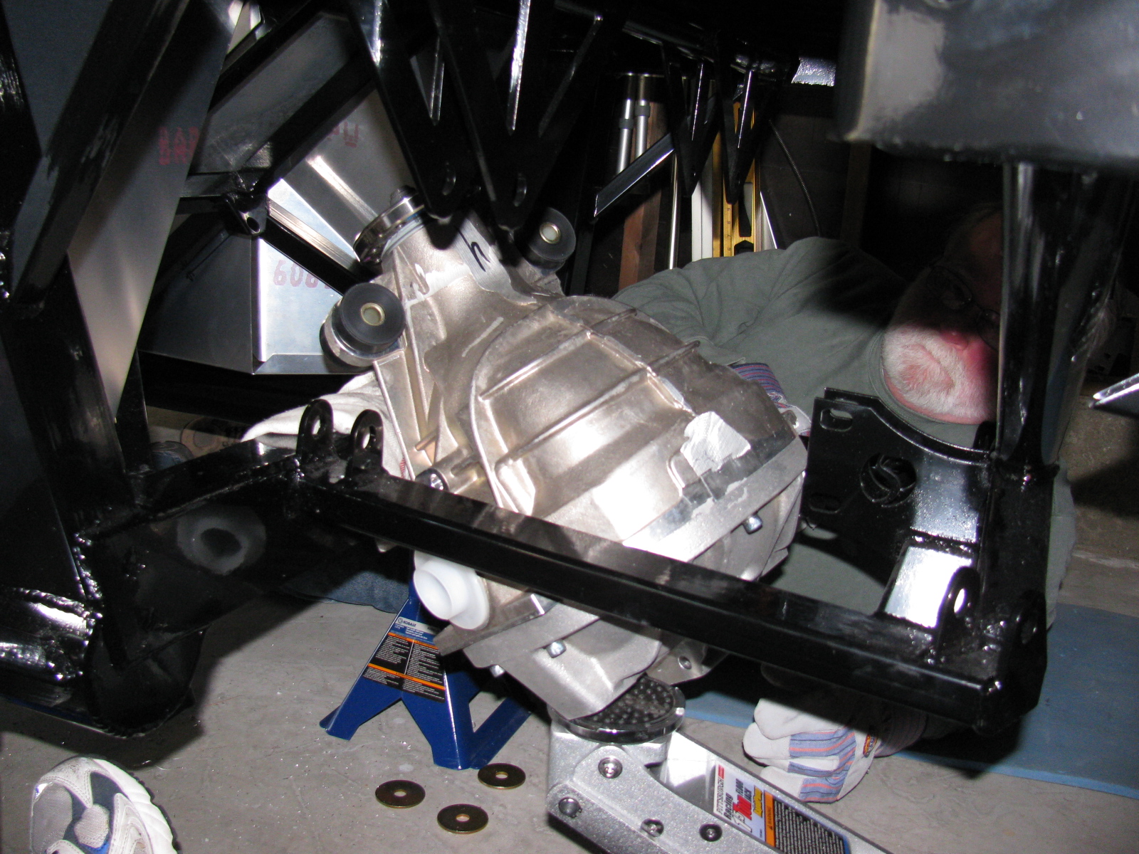
Since my ham radio friend Larry was going to stop by for a visit, I decided it would be a great time to get him to help me boost the rear differential (pumpkin) into the rear suspension cage. The Factory Five Racing assembly manual calls this unit the “IRS center section.”
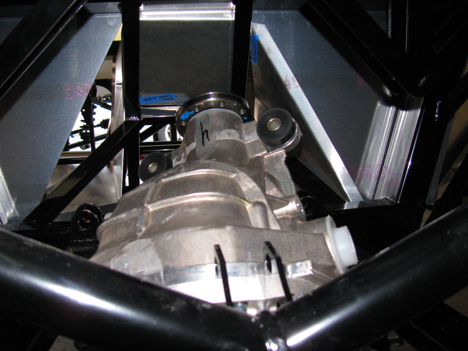
There are many posts on how difficult this step is. The manual says, “It installs from the bottom with the driveshaft flange pointing straight up and the axle holes lined up front to back with the chassis.”
Err. So that means the giant 70 pound, lop-sided bowling ball like thing must be pushed up sideways, 90 degrees from the way it mounts onto the frame, and then must be twisted 90 degrees in the opposite direction to drop into place. This cannot be done safely with just one person. I found out that this is actually impossible to do with two people.
After several long hours and a phone call to Spider Larry, the pumpkin still refused to go into place.
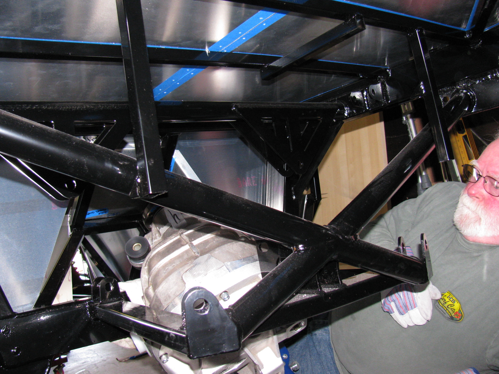
I began to think about getting a grinder and removing any offending protrusions on the differential case and chassis to make this thing fit. My ham friend Larry had to leave, but a neighbor showed up, who also happened to be a car builder. I put Phil to work right away…
We tried a different route, maybe through the X-member at the rear of the chassis could work. So we used the jack to lift the differential high enough to check. We made a few measurements. No way.
We measured again, and noticed that no matter how you turn this pumpkin, it will not fit past the rear cover mounting plates.
We decided to remove the rear cover.
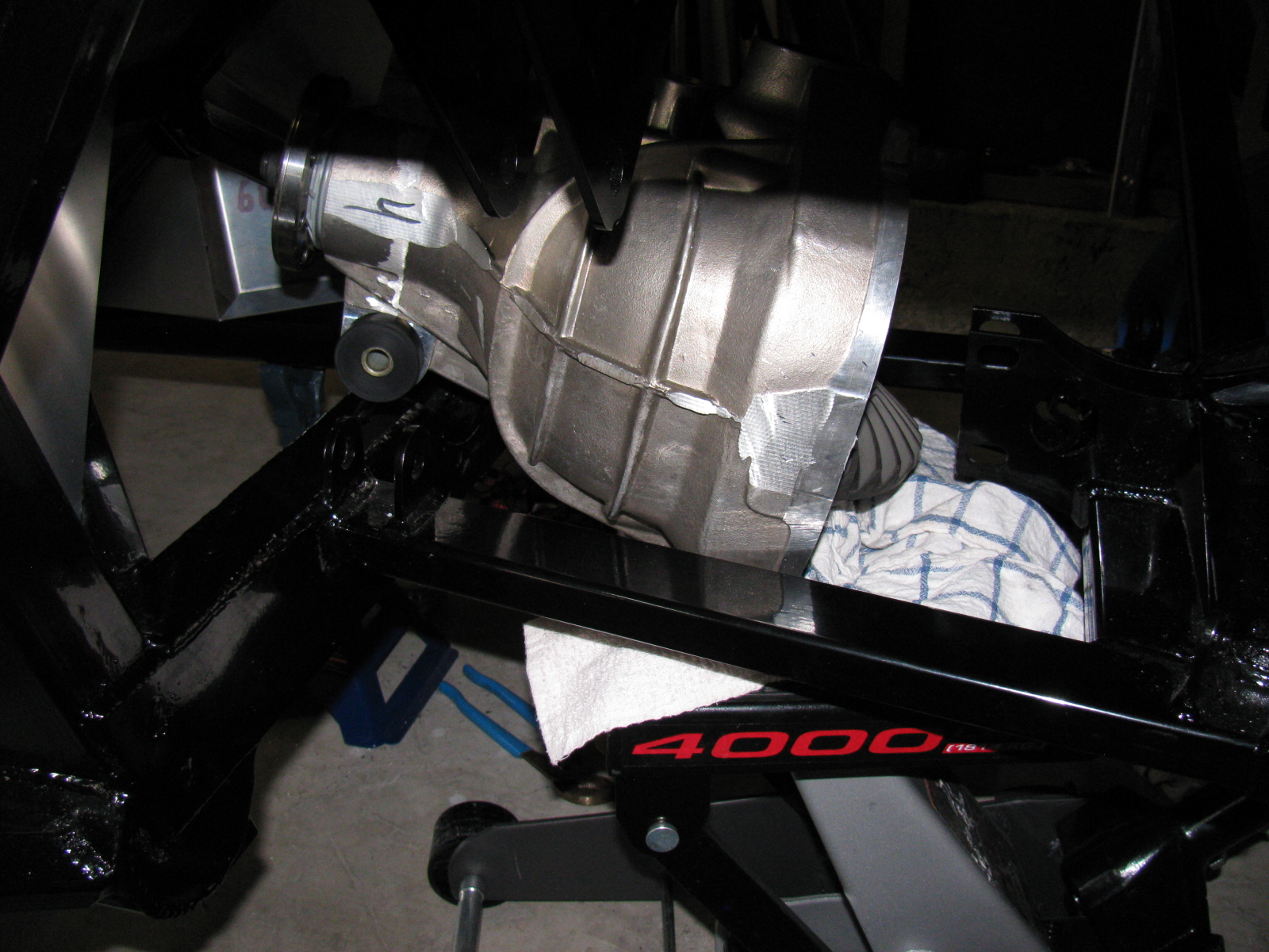
After unscrewing ten Allen bolts, and giving the rear cover a light tap with a rubber mallet, the cover popped off, very much like breaking an egg. To gain another inch of clearance, we removed the two plastic dust caps from the axle holes. Verifying that the diff does NOT have to come apart to mount the rear brakes, we put it back on the jack. Modifying the instructions, we lifted it with the driveshaft flange pointing up and the axle holes at a 45 degree (not 90 degree) angle, and pumped the jack. Now it went past the offending rear mounting plates, and into place.
Of course, now the differential must be re-sealed, so we tried a dry run with the rear cover. Yes, this will work. I currently have the pumpkin suspended above the mounting location, held in place with the jack, a 2×4, and a nylon strap. I will finish mounting this beast at the next build session.
Here are lots of pictures of the wrong way to do this. A video of this procedure would be most helpful, but I am sure most builders will have enough in their hands to not have a camera operator getting in the way.


So – take my advice, save at least 6 hours and lots of non-child-approved words and thrown objects, and remove the differential rear cover before you install your IRS center section. . . .


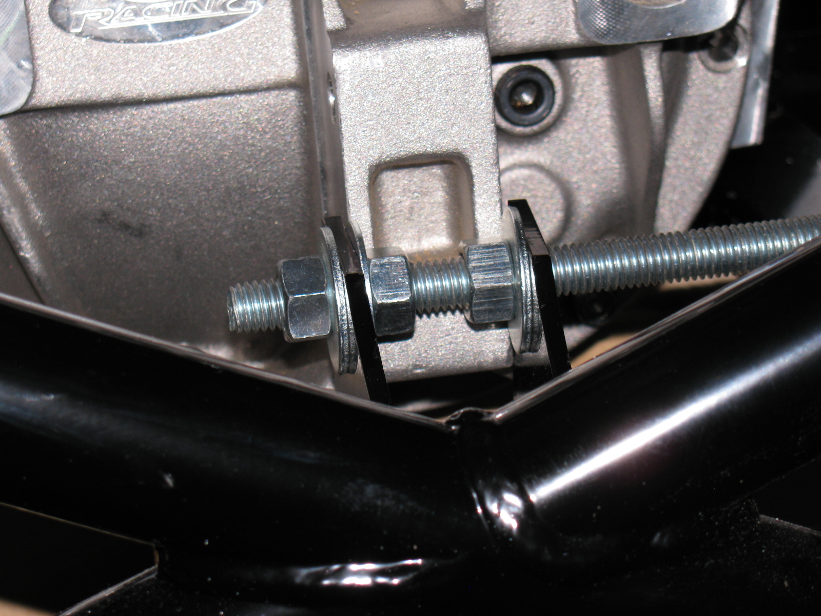
The rear mounting tabs (with the nice “5” logo laser-cut into them) are too close – use the threaded rod-expander trick to make it fit.
By the way – anyone else missing two nuts and bolts for the pumpkin mount? My parts list is correct, and yet I am still missing two fasteners for the standard width IRS differential.

I discovered I have the wrong adapter plates for the rear disc brakes, These are for the non-IRS version of the car. Jason at The Factory is sending the correct parts to me……

The front IFS is still not right, and the responses from the forums and the directions are confirmed by Jason at Factory Five Racing. Now the difficult task involves more un-building and hoping parts are not damaged. The ball joint on the passenger side needs to be removed and the upper A-arm top plate has to be flipped over. This is a direct result of an error in the Factory Five Racing Type 65 Coupe manual (revision 3E, July 2011) on pages 60 and 61 and 63 and 64.
The manual says to install the ball joint into the upper control arm to make “a left and a right.” I did this, and now must dis-assemble one of the ball joints. A new upper control arm is more than $200, so this is a costly error if I am not able to correct this.
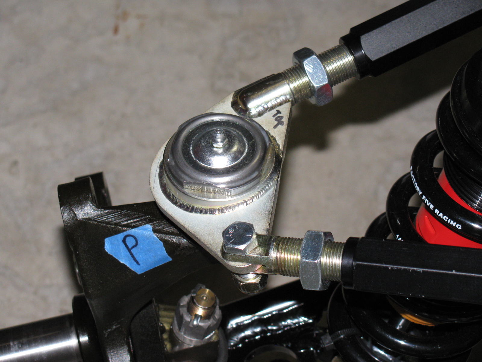
The correct orientation is shown on the driver’s side of the suspension. The passenger side is incorrect. This assembly is difficult to describe in words, so it is best shown with pictures.
Here is the driver side showing the upper control arm and the ball joint mount on the plate – see the wedge-shaped, “thicker” end at the apex of the triangular plate? This is correct.


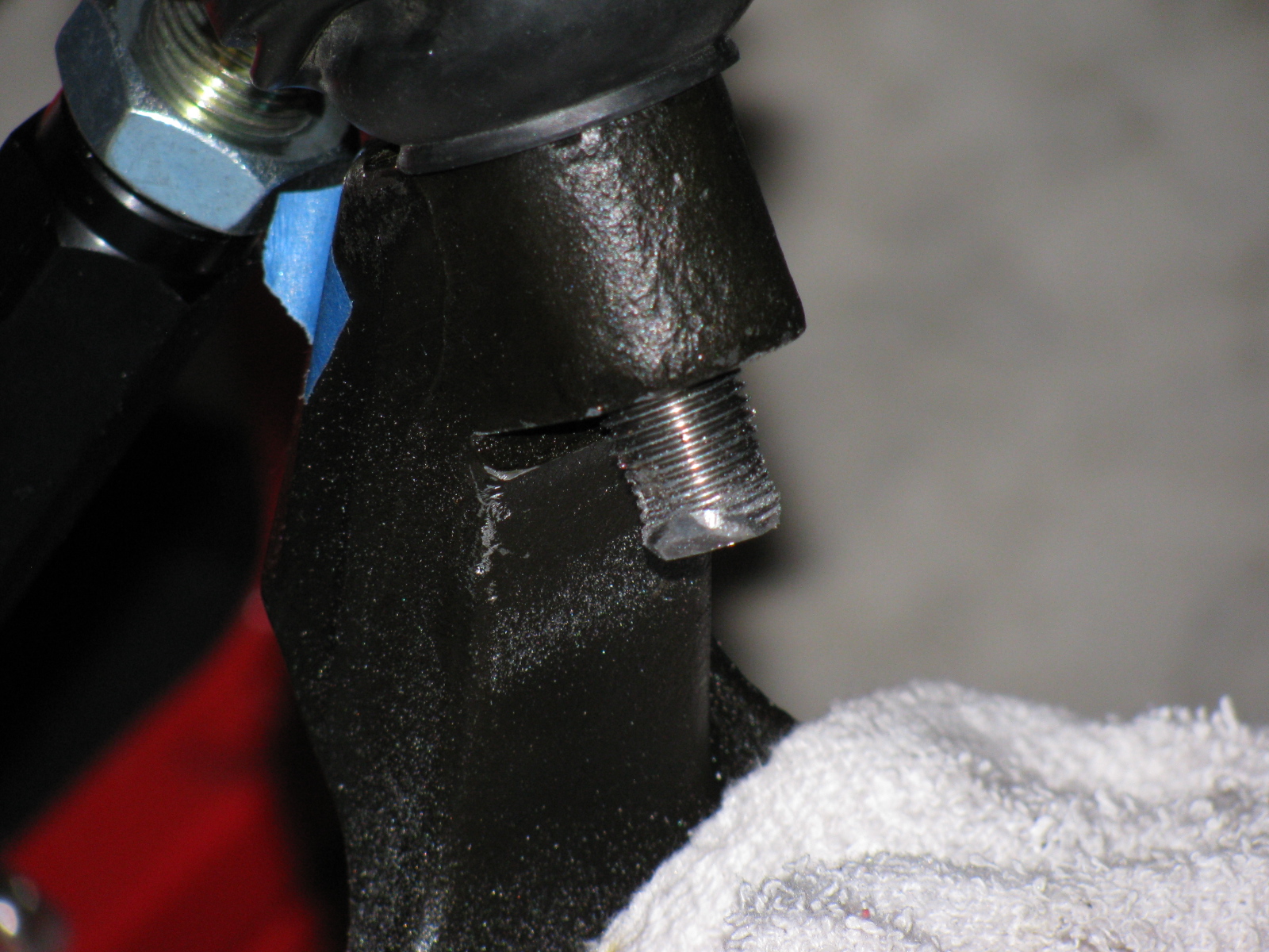
This is the passenger side upper control arm. See the thicker wedge-shape on the opposite side of the apex? This is incorrect (wrong).


I dis-assembled most of the front suspension to get to this ball joint. However, the ball joint fits into the spindle via a tapered hole. . . meaning that some force must be applied to remove the ball joint stem from the spindle. I started by tapping – then pounding – with my plastic hammer, since I did not want to damage anything. No good. I changed to a scrap of oak and my ball-peen hammer and hit it hard for several minutes. Still no good. I got rid of the piece of wood and really slammed with the ball-peen hammer. Finally, the stem popped loose.
Of course, this created a mushroom on the ball joint stem, and it would not come out of the hole. I filed around the mushroom and finally separated the ball joint from the spindle. I should be able to file or grind the stem so the ball joint can be re-used.

Mushroom on the stem!
Removing the ball joint requires dis-assembly with 450 degrees F (since I used Permatex medium strength thread locker blue), a vise and a big wrench with lots of grip and torque.
I tried several times, but my vise just isn’t gripping the ball joint properly, it slips off. I need a bigger vise and a torch for this. My bench vise is too small.
Cutting the Dash
Since I could not remove the ball joint, I decided to move to another part of my project – cutting the dashboard in half. This is a popular modification that will increase access into the area between the dashboard and the firewall. This area will soon be stuffed with wiring and air conditioner ducting, so the dashboard had to be cut sooner or later.
I wondered how this was done, should I leave a “lip” on one of the sections so I can patch the panels together? Or do I just slice along the fold? What is the safest way to do this with my power jig saw?
It turned out to be easier than I thought. Here are some pictures of the cutting operation . . .

I used some duct tape and a wood scrap to hold the dashboard in place for the cut. My trusty Makita power jig saw did the trick.

I will use a piece of aluminum angle stock to mend the two sections together.
I may make a new dashboard front panel, especially since the original one has several things wrong. For example, I ordered the “modern gauges” option. There is no mention that the modern gauges are smaller than the vintage gauges. The dashboard comes with cut-outs for the larger gauges, and a triangular-shaped adapter plate for the smaller gauges. Also, the steering column hole is in the wrong place, as mentioned in a previous posting. If I knew this was going to happen, I would have ordered a plain, non-drilled dashboard – so if you are planning your order – consider asking for an un-cut, un-drilled dashboard and make custom cut-outs where you want them.
Cookie Sheet Heat Shields
A few weeks ago, I found these cookie sheets in the close-out bin at the grocery store. They have nicely rolled edges and they happen to be almost the right size for the footboxes.


The amazing part about these cookie sheets is the angle at one end – it exactly matches the angle at the back of the driver-side footbox. I will mount them with 8-32 machine screws, spacers and locking nuts. I will also add a layer of insulation (Cool-It mat) between the heat shield and the footbox panels.
I am no longer sure if I want to use the Rust-Oleum BBQ paint for my firewall and other panels. I did a paint test this weekend, and the paint is quite soft, and scratches easily.
The Battery Mounting Plate
After noticing how soft that BBQ paint is, I decided to do some more paint testing. This is the battery mounting plate. It is made of steel, and it is already starting to rust. So I decided I should paint this part and the other steel items soon.

I used Rustoleum Appliance Epoxy paint for this test. This is my standard paint for radio and electronics projects. The finish is very hard and glossy, the cured surface is washable and no primer is needed. However, it is not meant for heat, the maximum temperature is 200 degrees F.
I prep the surface by scuffing the surface with 80- or 150-grit sandpaper on a random orbit sander, followed by a dish soap and water wash. I apply the paint in three or four very light fog coats and the surface becomes slightly textured. I may go with this paint, if I can find a suitable color. The last time I looked at spray paints, this appliance finish comes in white, almond and black. Too bad it does not come in silver or gray.
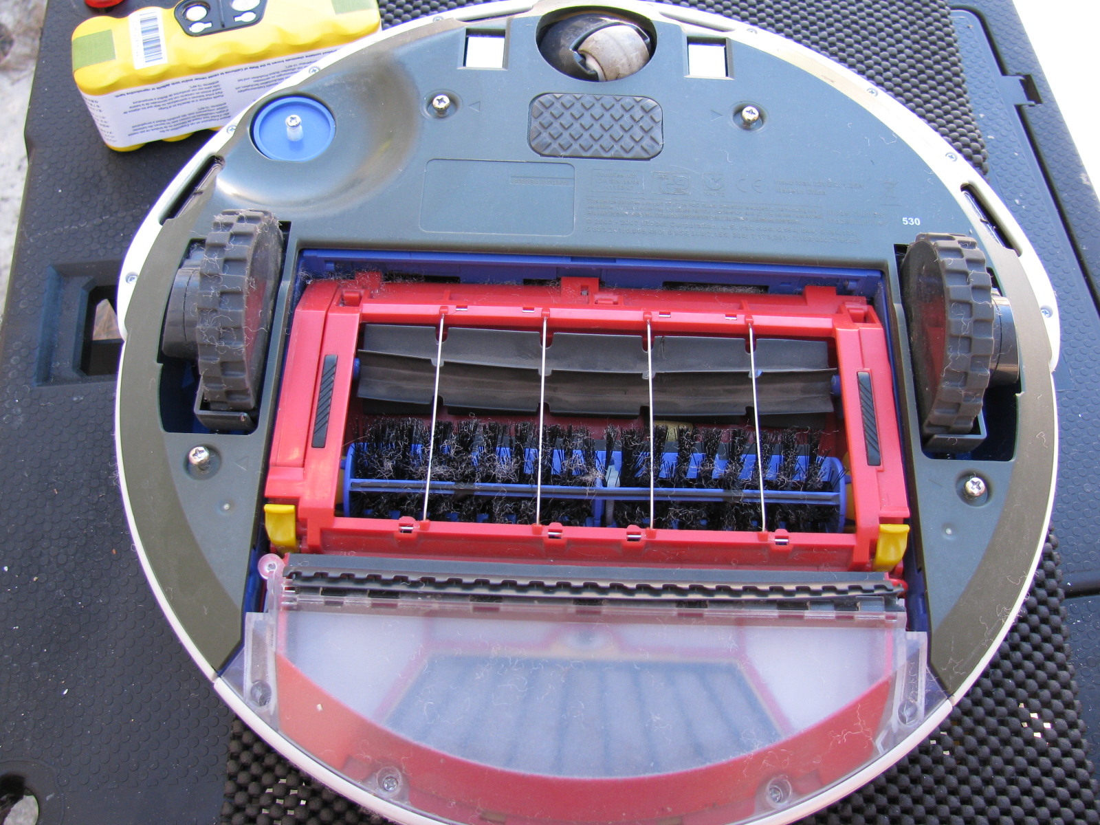
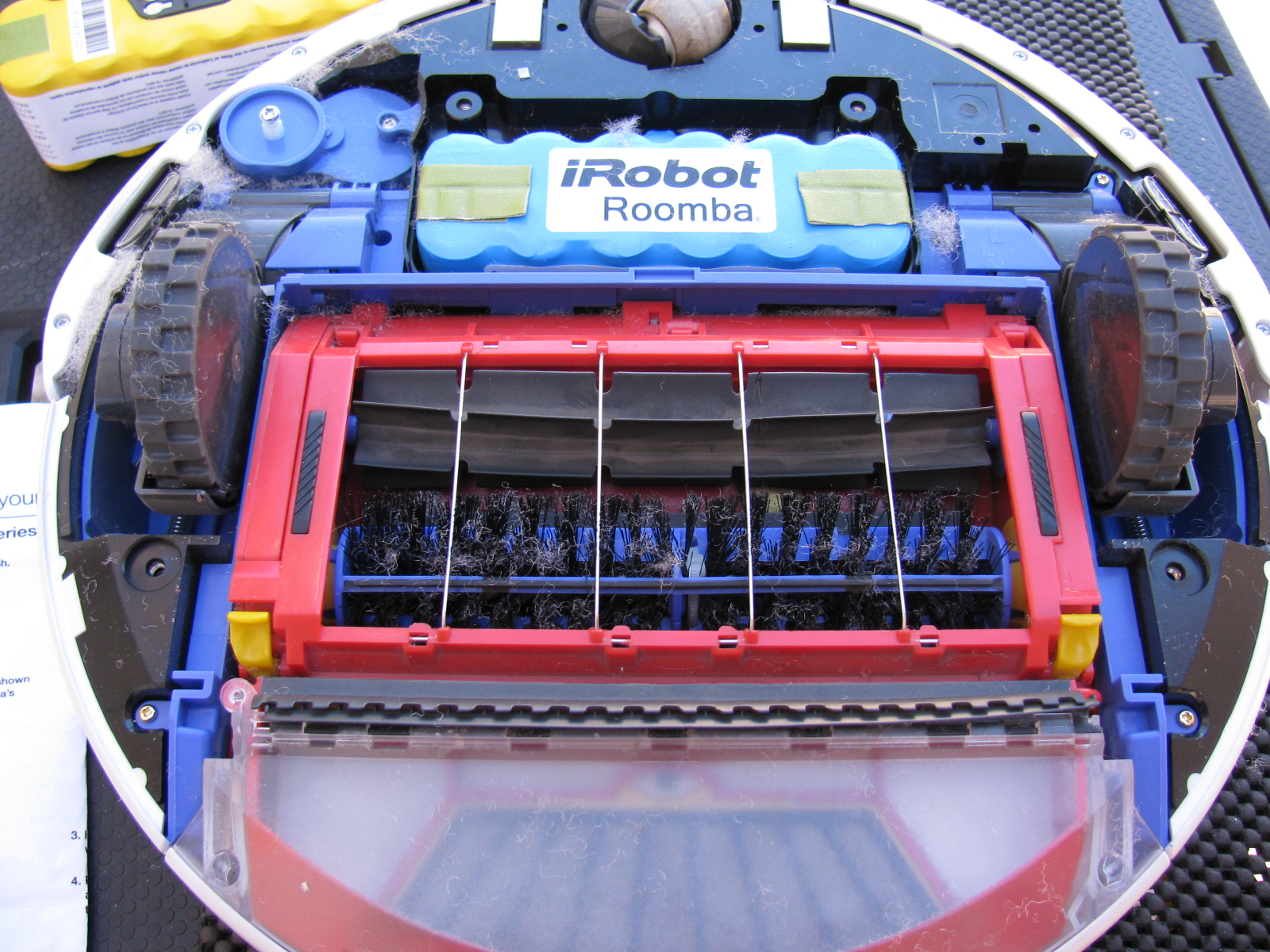
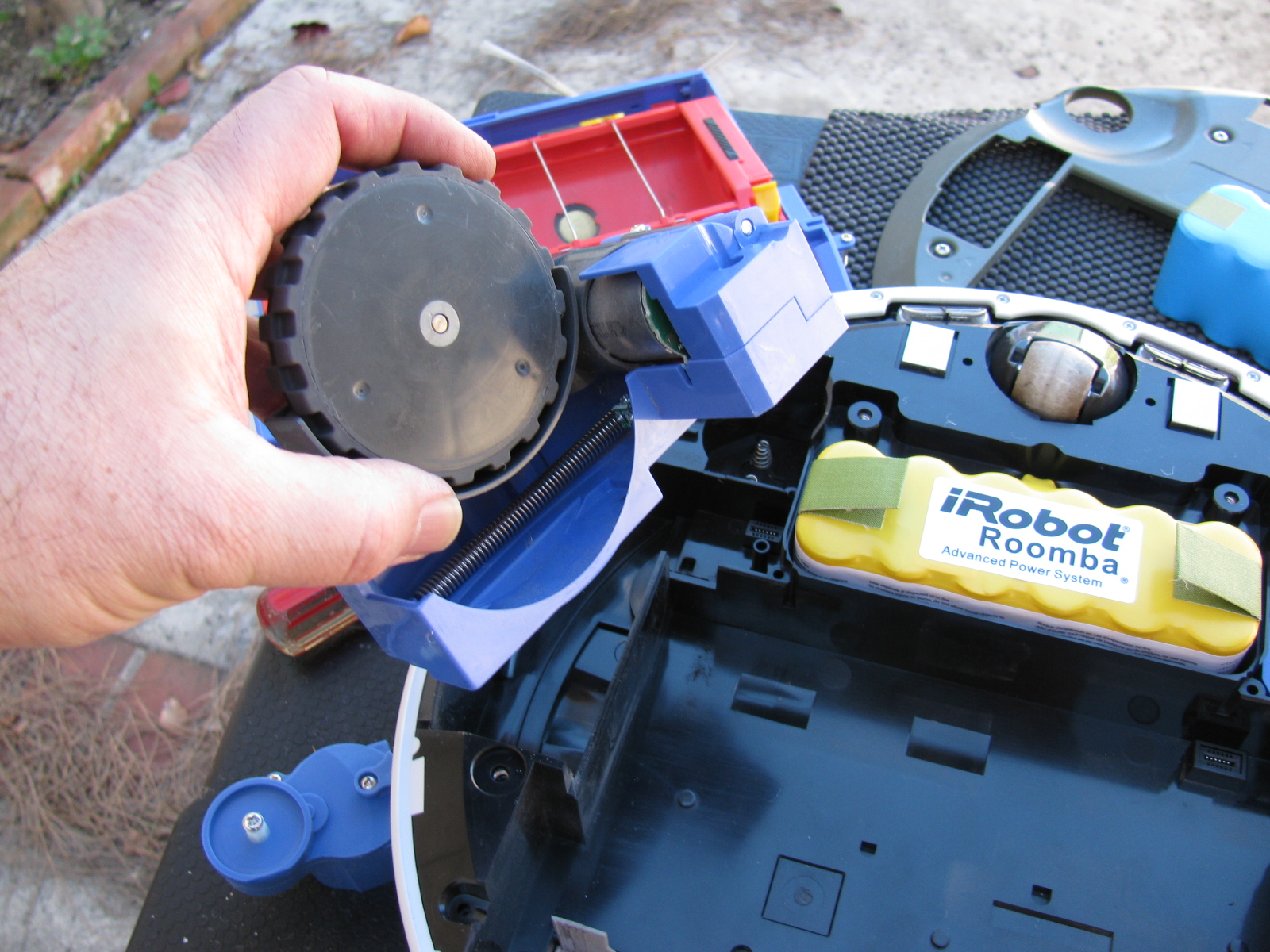
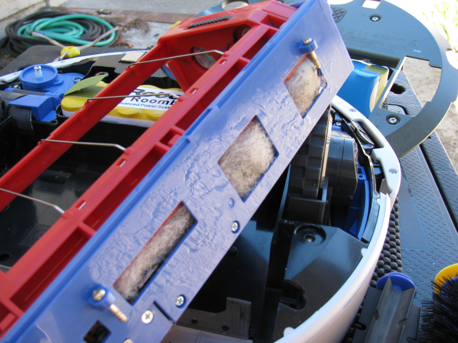
Roomba Battery-Ectomy – Vacuum Cleaner Battery Replacement
After almost three or four years, the battery pack in my Roomba 530 stopped taking a full charge. I re-newed the charge cycle several times, but the Roomba would run out of charge before completing a single room. So I performed a battery-ectomy on the Roomba. It needed a good cleaning inside the chassis anyway, so this was something I needed to do. You can see the debris inside the mechanisms that are impossible to clean unless you open the case. I used my shop vac to suck out the junk inside the various nooks and crannies inside the Roomba. The new battery has a larger capacity and should provide a longer running time. This will be good, since Roomba will help increase my time in the garage and other non-house cleaning activities. . . .
Here are some pictures. . .


I am working on several things on the car at the same time. Whenever I get stuck or run into a problem, I move to a different part of the car to build. At some point, things will meet up and progress in a more orderly fashion, but at this stage, nothing is complete.
This Factory Five Racing Coupe project is consuming my life. Even when I am sleeping, I have dreams about the car, the building process or driving the car.
But lately I have been having nightmares about the car….
Front Suspension Re-Do
I managed to install a part on the front suspension upside down and backwards. Of course, like a lot of automotive things, in order to get to that part, a lot of other parts must be removed first. Some parts required a tremendous amount of torque to install. These are parts that should never “fall off” like anything in the front suspension and wheel mounts.
So, one of the chores I had to do was to remove the front wheel bearings and hubs. I tried to remove the mechanical lock nut with my ratchet, but it would not budge. This is a good thing, since this one nut fastens the wheel to the car. Installing these parts required several very hard whacks with my plastic hammer and several Rated R and X words and phrases. I could not help but wonder how those parts would come off if I ever needed to repair or replace them.
Reading the forums made me lose a lot of sleep, since it seems that a lot of fellow builders have had trouble with this part, too. I bought an AC-operated impact wrench and some very large (36mm) impact sockets to remove the hub nuts. As a back-up, I also bought a large 1/2-inch drive breaker bar and a piece of pipe to increase the torque if needed.
I called my friend Larry over for some assistance.

Surprisingly, the breaker bar made the hub nut come right off. Even more surprising is the condition of the spindle where the wheel and bearing mounts – it still looks brand-new and without any distortions or scratches.

After purchasing the impact wrench, Larry sent me an e-mail advising me to not use an impact wrench on the front hubs, because this may damage the wheel bearings. I took this advice, and returned the impact wrench. Good thing I did not open the box. . .
Interior (Cockpit) Aluminum Panels
After the problem with building the IFS, I decided to “dry-fit” all parts from now on. This way I can verify everything is correct – or fix things that are wrong – before tightening the parts into place.
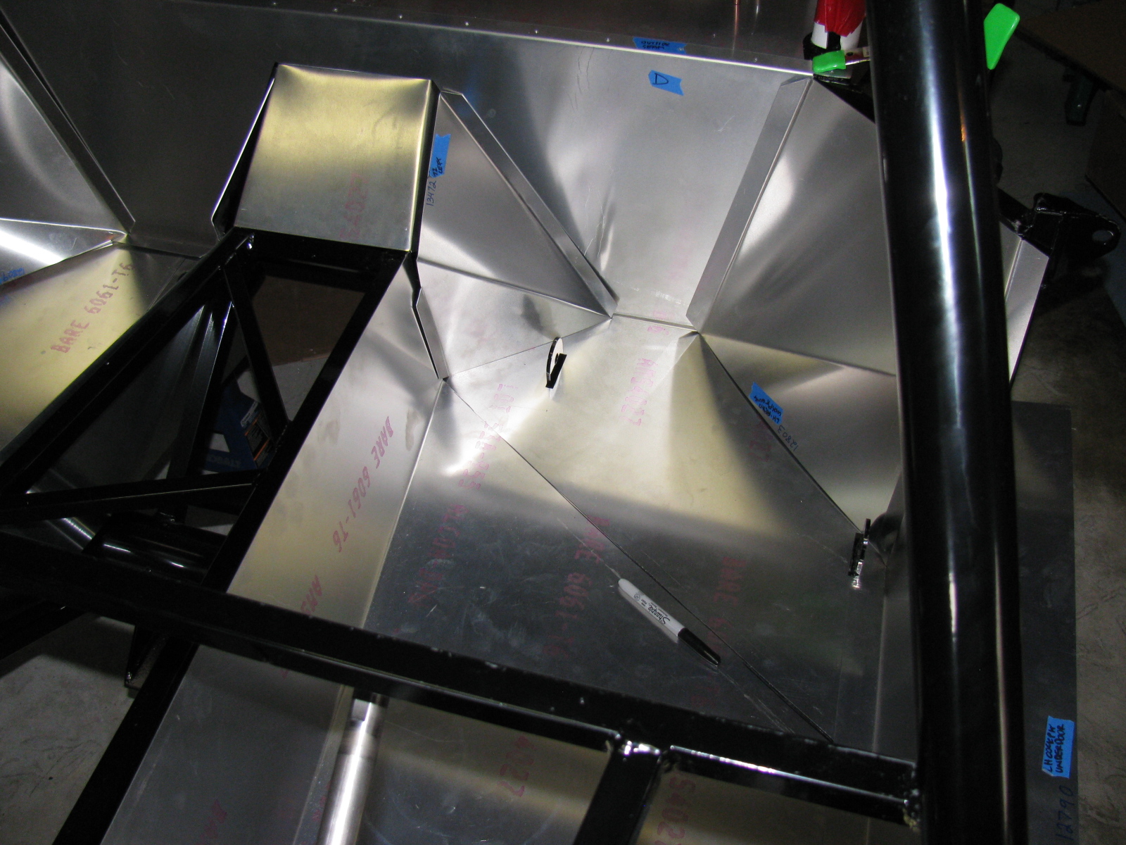
I decided to do some more work on the interior sheet aluminum. Compared to some of the other tasks, fitting the aluminum is easy. I made some diagonal cuts along the floor to make the parts fit easier, and to prevent scratching the nearby interior panels. By cutting the single large pieces into multiple smaller pieces, they will drop into place, rather than bend and scrape into place – preserving the painted surfaces.

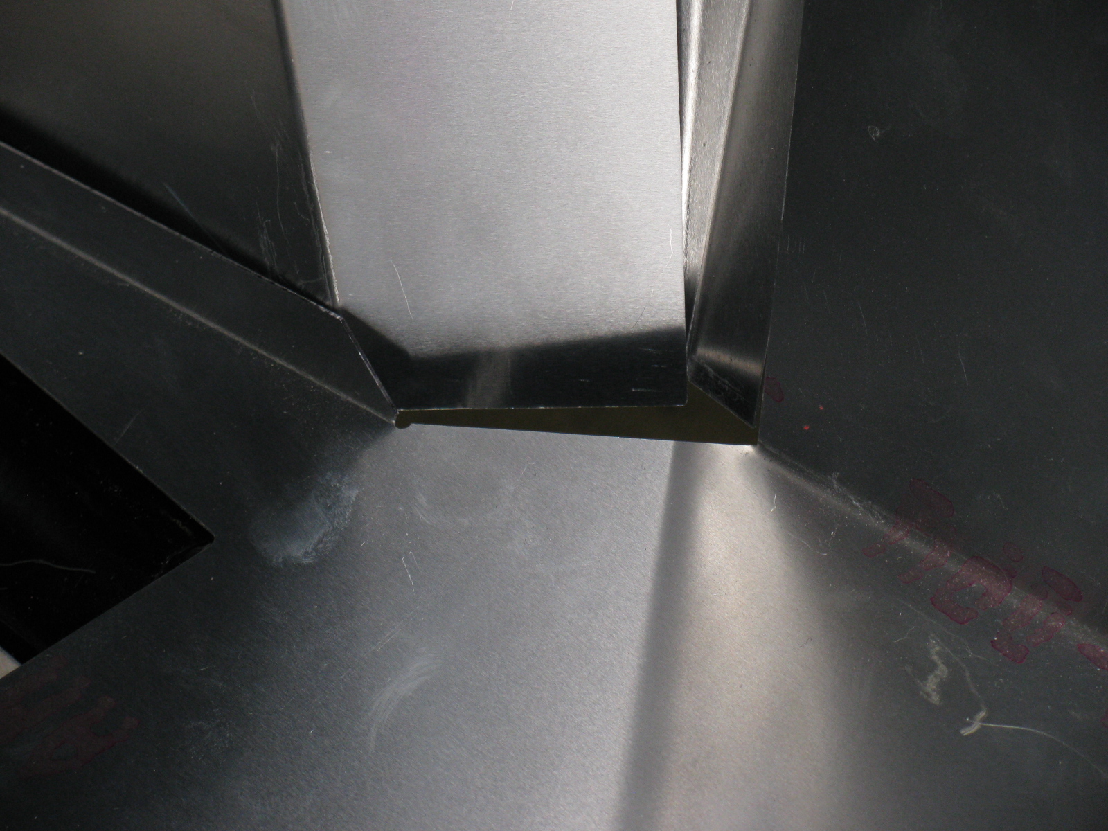
The seams and bend directions are hard to see in these pictures, the aluminum sheets do not provide enough contrast. I may use masking tape to show where the parts go and where the seams meet next time. As I said, this is the first attempt to fit the cockpit aluminum. Based on old Factory Five Racing forum posts, it looks like my aluminum panels have been improved somewhat. The only poorly fitting space is this big gap on the driver side, right at the corner of the transmission tunnel.

I may either trim the mounting tab behind one of the panels, or just install some sort of patch over the top. Overall, though, this Generation 2 Coupe seems to have better-fitting interior panels, so far.
Dashboard
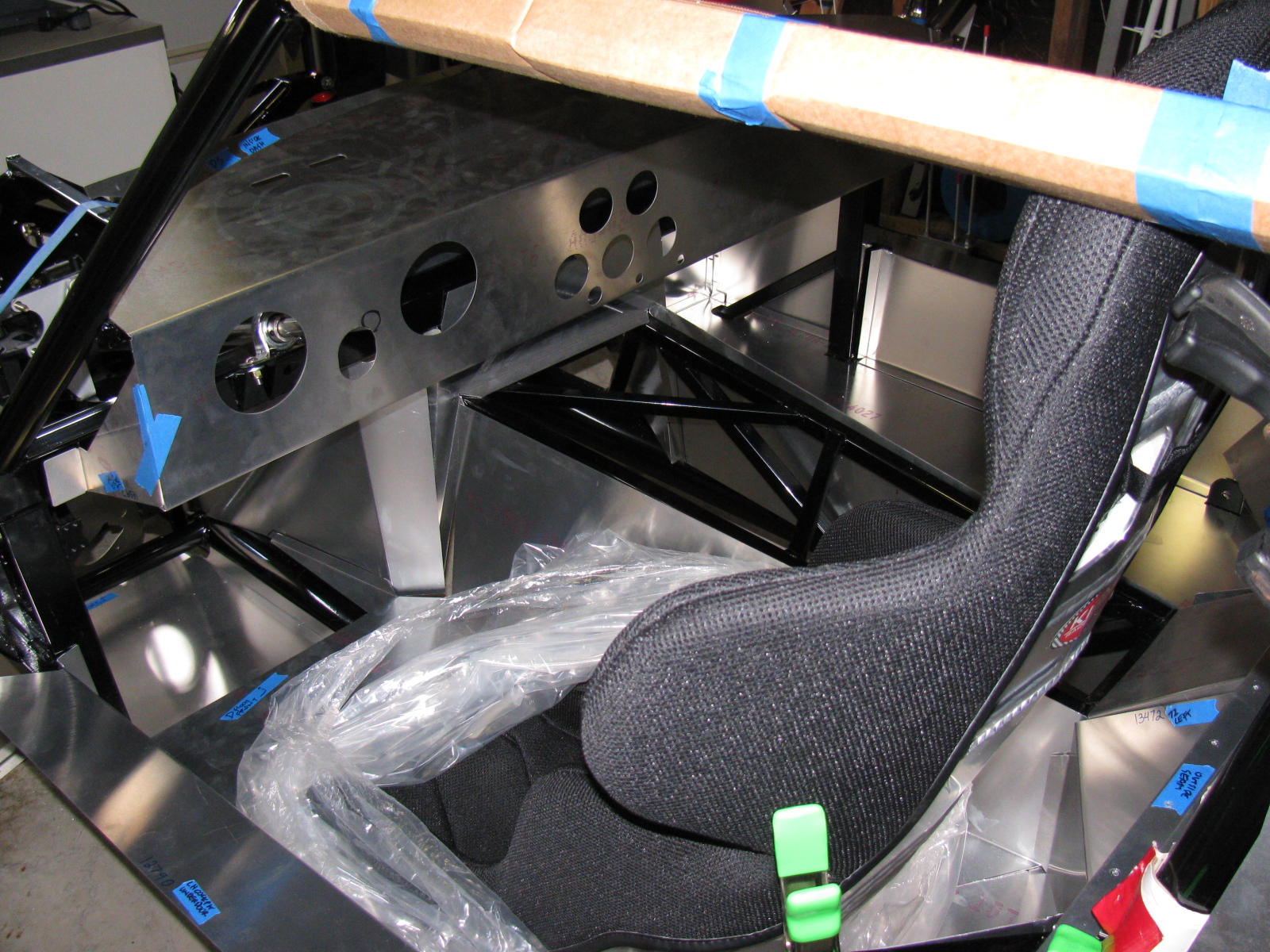
Here is an example of something gone wrong —

Notice the odd-shaped hole for the steering column? The mounting location for the steering shaft is not straight and parallel along the ladder structure in the driver side footbox and clutch quadrant. As I examined all the parts in this area, I believe the factory did this because of an interference issue with the brake pedal. If the steering column shaft were to run parallel to the ladder structure, it would block the brake pedal actuator. Moving the mount – but not compensating for this on the dashboard panel – makes this problem look worse than it may be.
I used a nibbling tool, a round file and a sanding drum to enlarge the hole for the steering shaft.


A popular modification to the dashboard is to cut along the bend, making the one long piece dashboard into two long pieces. This enables access to the inside of the dash from the top as well as the front, and will make installing and maintaining dash components such as gauges, air conditioner and plumbing much easier. I will make this cut at the next build session.
I just have to figure out a way to disguise the big and ugly hole in the dashboard. . .
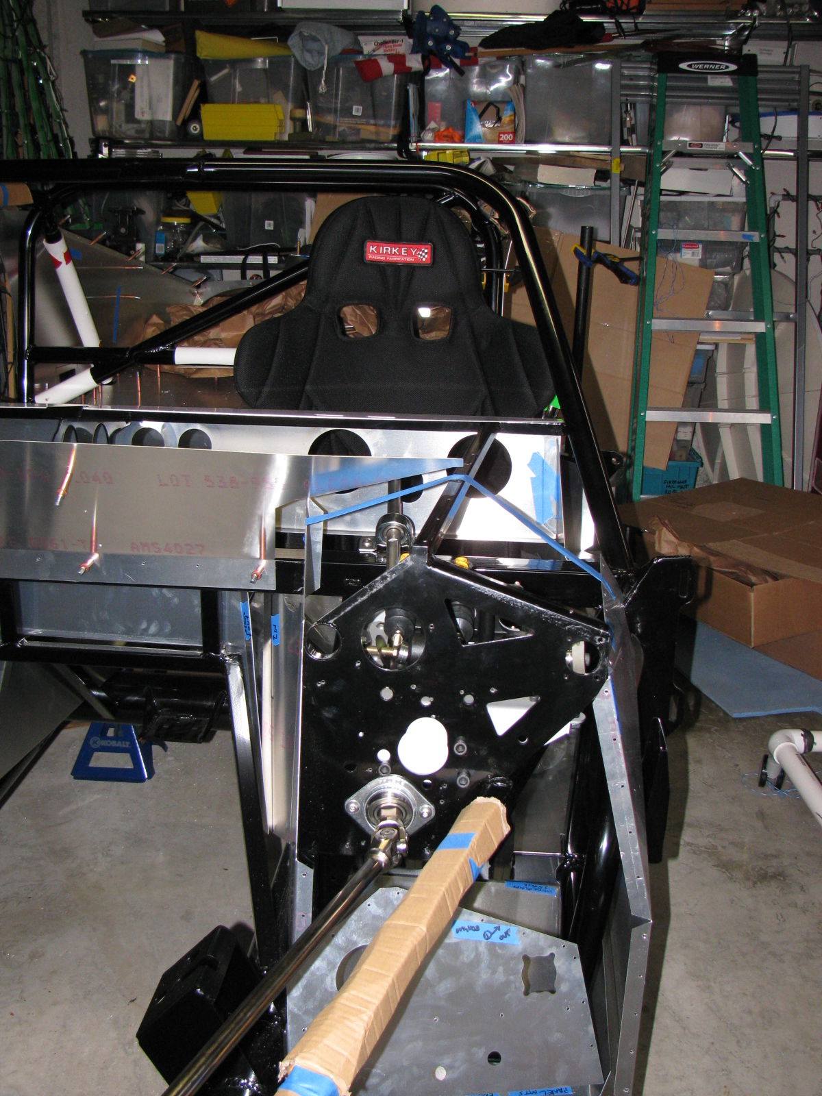
The Racing Seats
I placed the Kirkey high-back racing seats to see how it fits, and although the steering wheel is a bit toward the passenger side, I think it will be all right.


Clutch Quadrant and Pedal Box
Many Coupe builders owe a lot to a guy named Chris, who has documented his Type 65 Coupe build experience with lots of pictures. (I added a link to his flickr photostream in the Automotive Links section.) The Factory Five Racing assembly manual left an entire section out for us Complete Kit builders. There are no instructions for the Wilwood pedal box and clutch quadrant assembly. Thanks Chris for sharing your images!
Anyway – here are some pictures of my Wilwood pedal box and clutch quadrant. I do not have too many fitment issues here, except for the mounting points to the 3/4-inch tubes – I will have to wedge the mounts at the firewall in order to securely mount the pedal box to the ladder structure. I painted my footbox mounting plate with silver Rust-Oleum BBQ paint. I wanted to do a test to see how the color came out and how durable the finish is. I like the color, it is much better than the raw steel and hopefully will prevent any rust from forming inside the car.


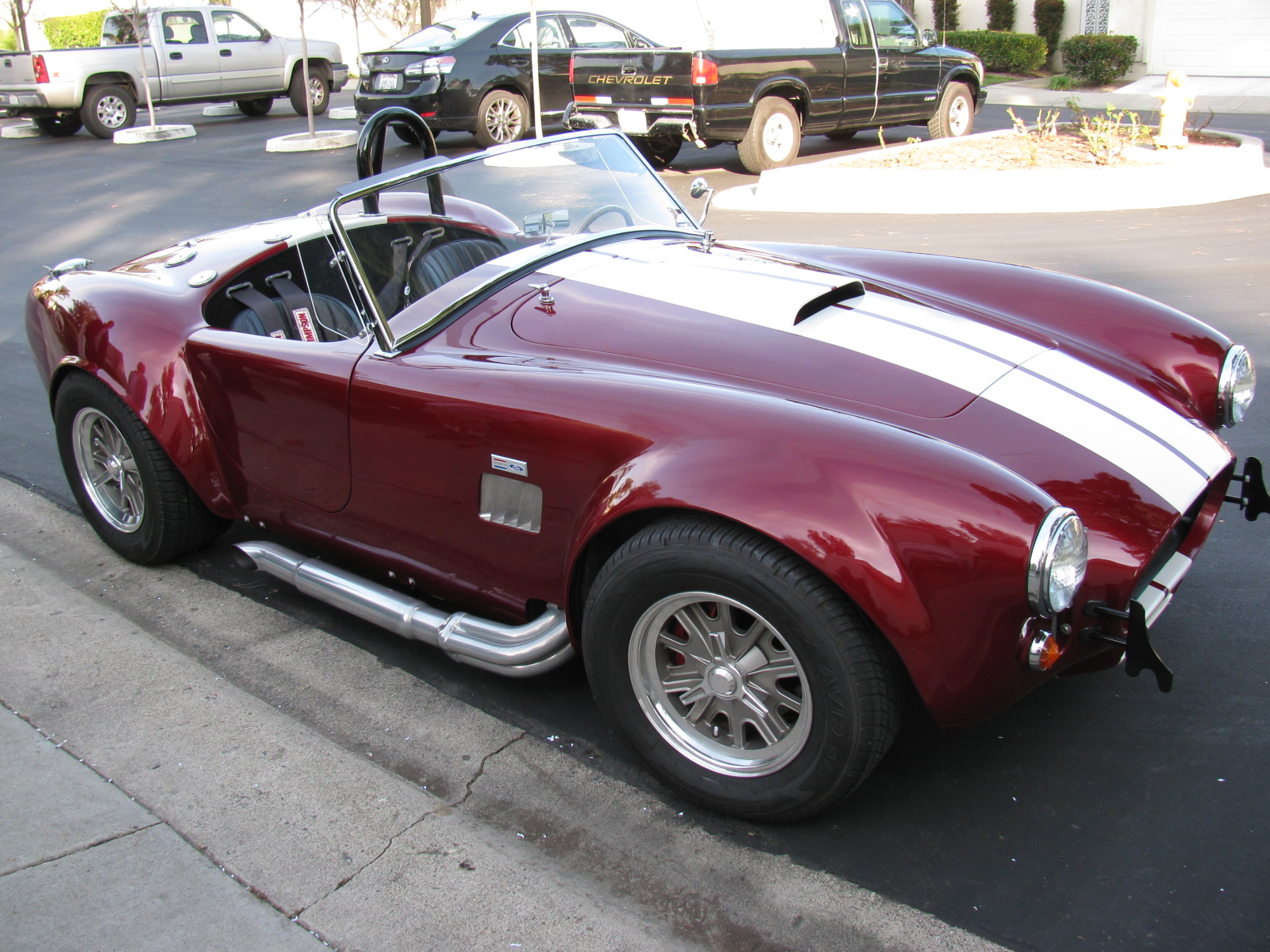
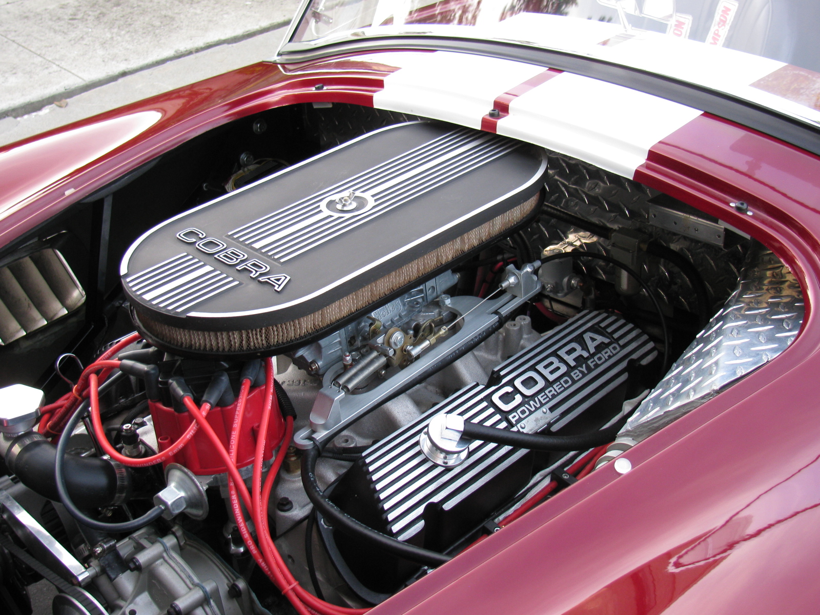
A Roadster Driver Visits
Rick, a neighbor and Roadster owner, stopped by for a visit. Here are some pictures of his very nice car. Rick did the paint job by himself in his garage – I am very impressed with the way the finish came out – take a look!


The front steering arms came in the day before Thanksgiving. That meant that I could continue building the front suspension. These little cast iron parts were the things holding my progress:

I installed the steering arms without too much drama. Installing the front hubs onto the spindles was another matter. The instruction manual says something about them being a tight fit, and that is true. I did not want to damage anything, so I used a PVC pipe elbow (remember the body dolly? This was a left-over part from that…) to protect the hub, and I used a plastic hammer to pound the hub into place. A few whacks and it slid right in. I hope that I won’t have to remove them someday – they are stuck on really tight.

And yes, a coupler or a T would have made a better anvil, but all I had on-hand was this elbow. Anyway – the hubs are now mounted to the spindles.

Torque spec for the hubs is 225 to 250 lbs/ft. This is a lot. The nut takes a 36mm socket and I bought one earlier (Coin Star money) just for this step. It took a lot of cranking on my 1/2-inch torque wrench to meet that 250 lb mark. I thought I was going to lift the chassis off the jack stands!
Thanksgiving Ribs
Meanwhile, I prepared some Kansas City Style pork spare ribs for Thanksgiving dinner at my sister’s house. I was in a hurry, and forgot to completely trim the ribs (the cartilaginous tips). I did, however, remember to remove the pleura – the silver skin on the back of the ribs.
If you don’t know about removing the skin from spare ribs, then I am sure you may have experienced eating that stuff somewhere. The pleura is the tough membrane that you might see on the back of the ribs. If left on, it blocks the spices and will never get soft after cooking – it is sort of like chewing gum, and ruins the eating experience….
Anyway, they were still very tasty, although I was out of paprika. No one else noticed it missing – but I sure did.

Ribs with a dry rub. I made two racks for Thanksgiving this year.

Smoky goodness.
After Thanksgiving Turkey
Per my tradition, the day after Thanksgiving, I went to the local grocery store and found a good deal on a fresh 12-lb turkey. I decided to try a recipe from Steven Raichlen’s Primal Grill TV show – see Orange Brined Turkey.
Strangely, both the book and the website say this is for turkey breasts. On the DVD, Steven smokes a whole 12-lb turkey. At any rate, I salivated over this since last year, and finally got to try it. Take a look at my version The bird is a hen, just over 12 pounds . . .

Orange brine for the turkey.

I need a bigger bucket or something for brining the turkey. I turned her (it’s a hen) over in the middle of the night.
Back to Work on the Coupe
Since the turkey had to soak over-night, I went back to the Coupe project. I started to assemble the front disc brakes, when another delay came along: No “supplied grease” for the disc brake slider pins. So I went onto the Factory Five forums and searched on what sort of special grease this might be. I almost skipped this step, but I am glad I did not. Lots of bad things can happen if the brake calipers stopped sliding on the slider pins.
Turns out the grease is special – the grease must be silicone-based, high temperature and must not affect rubber. So I did some more research and found this stuff: Permatex Ultra Disc Brake Caliper Lube Silicone Formula Item #24115. High temperature, silicone based and intended for brake caliper use.
There are some little spring clips that go into the brake housing, and some rubber boots that fit onto the caliper slider pins. The pictures are not too clear and I had to do some fiddling with the parts to make things look right. Here are some pictures that may help other builders. . .

This is the clip that goes into the long slot in the middle of the housing. If you are struggling to get it in, it is probably backwards. Hold it like this and insert it into the housing from the inside. It will just pop into place with a little bit of pressure.

The caliper slider pin boot is easier to install if you “un-curl” it first, like this.

Then you can push the little lip into the shallow groove in the pin. . .

. . . to make it look like this.
Since I was at the car parts store, I also bought a box of disposable gloves and some adhesive for the aluminum panels. There’s a ton of postings on what adhesive to use on the Factory Five Racing car projects. Many different adhesives are mentioned. But there was one build gallery that I found, and I am going to use the product they used – it is Permatex Ultra Black RTV silicone gasket maker, Item #24105. This is what Kirkham Motorsports uses in their projects, so I figure it would be acceptable in my Coupe build. Kirkham has an online assembly manual posted, it basically follows David Kirkham building one of his cars: Kirkham Motorsports Assembly Manual.
What Good is a Sale on Something When It’s Out of Stock?
Since I was running about getting the grease and other stuff, I decided to go tool shopping. A local hardware store chain had a 50 percent off sale on Makita and Milwaukee power tools this weekend – I thought this was the perfect time to go get that right angle drill I wanted. I got to the store, only to find no Makita or Milwaukee right angle drills available. I went to two stores and wasted half of my day looking for the thing. I decided to look for an alternative to the right angle drill – how about a right angle drive attachment? I did not find one of those, either. So I left the hardware store empty-handed – I think this was the first time that ever happened!
Back to the Turkey
After an overnight soak, the turkey is ready for the smoker.

Getting the Big Green Egg up to temperature (250 degrees F). Hickory chips were added.


I can never resist peeking. Orange brined turkey, after the first hour.

After the 2nd hour. I rubbed the turkey with butter and continued to smoke.

After 4 hours. Almost done.

Total time in the smoker: About 5 hours. Temperature in the thigh 170 degrees F. After a 15 minute rest, time to carve!


Yes, this is as tender and juicy as it looks. The mayo-mustard-triple sec dressing that is part of this recipe is very good. I think I will try this with lemons next time.
So not much work completed on the Coupe today, but the holiday weekend is not quite over. I hope to complete the front end tomorrow.
I’ve been busy with work and other chores so haven’t had much time to work on the car and update these pages – but – here is a re-cap of the work done over the last few sessions.
The day after the Welcome BBQ, I built a PVC pipe dolly for the Coupe body. It is made of 1-1/2 inch PVC pipe, some Ts, some 90 degree elbows and some casters from the “As-Is” bin at the local Ikea furniture store. I chose the plastic pipe because I had some connectors and lengths of pipe leftover from some other project. If I were to do this over, I would have made the dolly with 2 x 4s.


Next, I removed all the sheet aluminum from the chassis, marking the outlines of chassis tubes underneath. This is done to indicate where to drill holes for the pop rivets that are used to mount the sheet material on the finished car. This went pretty smoothly – except for the trunk area. It reminded me of one of those mechanical puzzles – you have to warp the trunk floor upwards and then slide and pull it toward the front of the car and then through the roof section. Or something like that. It is a tapered shape. After scratching the area just behind the seats – where the roll bar attaches – I decided there had to be a better way to get the trunk floor in and out of the chassis – this would be more important later in the build, because I will paint the trunk area. I decided to cut the trunk floor in half length-wise. Later, I found some posts in the forums that mentioned this, so I kind of re-invented the wheel on this one.
I used my power jig saw and a fresh metal cutting blade for this. My long saw guide was in another garage, so I had to come up with an alternative straight edge – a really long power strip worked fine. I centered a line on the trunk floor, and made the cut. You can see the wax along the cut line, this lubricates the blade and helps prevent the aluminum from clogging the blade.


The independent front suspension (IFS) came next. The steering arms are on back-order, but I decided to start building this section. The parts are beautiful, nicely powder-coated black. Some parts have a neat little detail built into them – see the “5” on the front lower control arm? Sort of like the hardware version of an “Easter Egg,” if you know what I mean.

I ran into a small snag at this stage. The mounting points on the body for the lower control arm were slightly off. I solved this by squeezing the arm into place with a quick-clamp. Easy.

A similar, but more difficult puzzle for the upper and lower shock mounts. A pair of aluminum spacers is used to center the coil/shock assembly on their mounts – the spacers were too long. This is a common problem, and it is documented on the forums. There are several ways to correct this, and I combined several hints to solve my issue. First, the upper mounts were a total of one-quarter of an inch too tight. I padded the rear-facing mounting ear with a rag, grabbed it with a pipe wrench, and pulled. It was surprisingly easy to bend that mounting ear to make it fit.
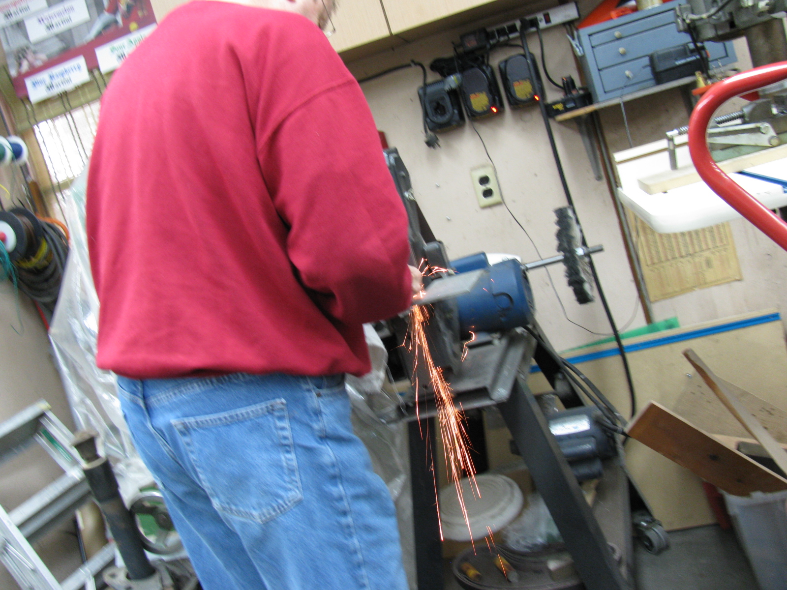
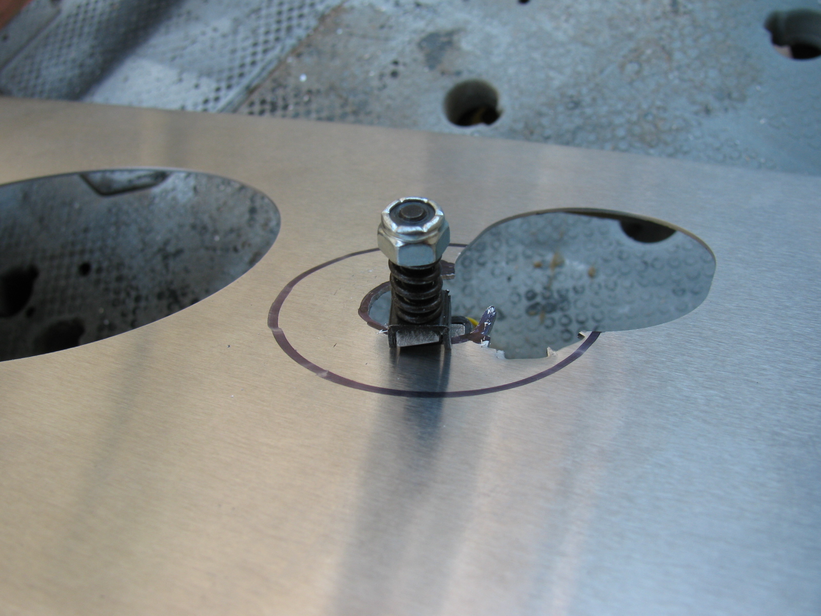
The lower mounts had a similar problem, but slightly worse, because there is no room for a wrench to tweak it. So, I used my new disc/belt sander to grind off about an eighth of an inch on each spacer. Because I wanted to make sure the ends remained square, I made a “sled” to hold the spacer and gauge the amount of material being removed. This 2-1/2 inch nut and bolt does three things: First, it safely keeps my fingers away from the sanding disc while holding the little spacer. Second, the side of the hex nut and bolt helps to ensure the spacer is 90 degrees to keep the end square. Thirdly, by screwing the nut so that the end of the bolt is the needed 1/8th of an inch inside the spacer, I can tell when to stop grinding: Sparks will start to fly when the bolt hits the sanding disc. (Something I remembered in 7th grade metal shop class – sparks can be an indicator of the type of metal – ferrous vs non-ferrous. How cool is that!)


Anyway – at the end of the day – Front suspension at 90 percent complete. Still need to attach those back-ordered steering arms and then attach the hubs.
I will start the rear suspension system next. . . .