Archive for the ‘302 V8’ Tag


I spent the last two weekends in the garage, getting back to the Coupe Project. It was nice and relaxing to lay on the creeper, under the chassis and working with tools again.
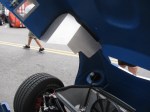
I had to modify the chassis in the pedal box area to allow more clutch pedal movement. This is a known issue in the Roadster forums, but not so much in the Coupe forums. This happened when Factory Five Racing changed the Wilwood pedal box – the old version would actually break. The new and improved pedal box moves the clutch pedal arm over to the left by about an inch or so, and the arm hits a brace, limiting pedal travel.
When the modification is done before the pedal box is bolted into place, it is a simple chore to make two cuts, chopping a small triangular cut into the frame member. This can be done with a reciprocating saw or maybe power jigsaw.
However, if the modification must be performed after the pedal box is bolted into place, the tube must be accessed from below, in an awkward angle. A small grinder tool would be ideal for this, but the only tool I have that will fit the space and the angle is a Dremel tool. It took me two half-day sessions to do this.


In the pictures above you can see the half-moon shape cutout I had to make. This is a view from under the chassis, looking up from the creeper. This will be painted black later. The tube looks normal from the top, so that is good. And clutch pedal travel is doubled, so free play adjustment range should be much better.
Since the brake system is installed, filled and bled, I removed the Clekos and riveted the lines in place. I changed several P-clip anchor points so it complies with my “routing and clipping manual” from the office. Unfortunately, I followed some other builders’ clipping, and mounted several p-clips upside down. Most of them will be under the car, and might be hidden from view when the car is finished. But I know they are upside down.
Here is a picture of how the clips should be mounted. This is the X-member in the front of the chassis.

Looks like I didn’t take a picture of the riveted clips. I will post them later.
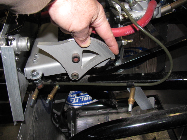
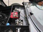
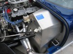
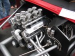
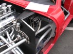
Next, I made a bracket to support the ECU for the MSD Atomic fuel injection system for my 302. This plate will secure the ECU and provide strain relief for the cables going in and out of the unit. It is on a plate so it can be easily removed if I have to work on the wiring or the ECU later. It is mounted with 1/4-20 stainless steel studs and nylon lock washers. It was raining so I was not able to paint this plate. Will have to do that at the next build session.
The passenger side footbox is on the left. Three stainless steel Allen head screws come through the wall and into the passenger box. The center photo shown the ECU engine cable going into the engine bay, and the right photo shows the MSD computer and plate inside the passenger footbox. Carpet will cover the interior, so a carpeted cover will be made to hide the ECU and wires when the car is finished.
I am also laying out the air conditioner system components on the chassis. I have to make several brackets and small boxes to mount the A/C components on the chassis.
As I was doing this work, I took another look at the battery box mentioned in an earlier post. It is installed with clecos so it can be removed. I think I want to mount the battery above the passenger footbox. Two reasons for this:
First, it will shorten the battery cables, decreasing the voltage drop.
Second, the “factory location” for the battery – in the rear center – blocks the rear axle pumpkin. So, when I have to change the oil or make adjustments, the battery must be disconnected and the battery and the box must be removed. Sounds like a painful procedure for a simple maintenance chore.
I will make a mock-up of this in my next build session. Stay tuned . . . .
Overcast skies and 10 percent chance of rain, after months of drought conditions….
The Pre-Party
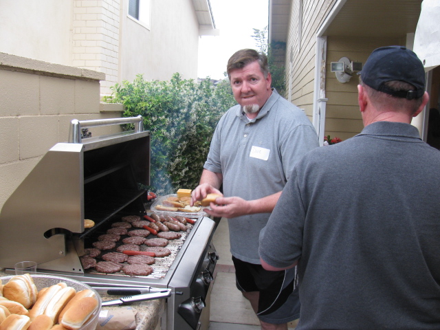
A generous tradition started by David Hodgkins. Here is our host at the BBQ, working hard to feed all of the guests. I met one of the Car Warriors builders from the East Coast Team, Mark Stackler.

David Hodgkins, our generous host of the HB Cruise-In Pre-Party
Another guest at the Pre-Party was Scott Merrell of Coupe Connection. He talked about the 8-stack induction system fitted on a Ford Coyote engine. Very interesting, and I may use that engine in my next project car.
The Event
More gray skies, but no mention in the forecast of rain. As usual for me, my focus was to gather as much info about Coupes as possible, so I can apply these ideas into my car project.
Also as usual, I had to look at all the other Factory Five Racing kit cars on display.
I noticed more completed 33 Hot Rods this year and more Coupes.
Highlights of the Day
I met and discussed body and paint with Jeff “Da Bat” Miller in the early morning. He has probably put the final finish on hundreds of Factory Five Racing cars over the years. Da Bat was the Body and Paint expert for the West Coast team on the Car Warriors Factory Five Hot Rod challenge.
I was lucky to meet and hang out with Karen Salvaggio and Jo Coddington as we visited with the builders and the cars on display. Karen and Jo were two members of the five lady team on the “All Girls Build” episode on Power Nation. The other ladies were Nan Gelhard, Cherielynn Westrich and Courtnie Provencher.
Here’s a picture of Karen on the left with Jo on the right. And that’s Sue from Just Get Dirty Garage in the middle. Sally Bean, one of the behind the scenes people from Factory Five, is in the background, making sure things are going as planned…..

Factory Five Racing Ladies

Factory Five Racing president Dave Smith introduces Jo Coddington to the crowd.
Meeting Peter Brock, BRE Racing
Peter Brock, the body designer of the Daytona Coupe, came to Huntington Beach for this event. I have several of Peter’s historical posters on my walls, but I wanted to meet him in person. Peter is a nice guy, and he truly loves the Factory Five Racing version of the famous Ferrari-killer from 1965.

Factory Five Racing president Dave Smith (right) introducing Peter Brock to the Cruise-In crowd. There’s Mark Stackler in the background.
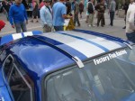
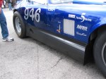
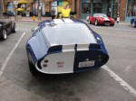
The Fastest Factory Five Racing Coupe in the World
On display was the SoFast Racing Factory Five Racing Type 65 Coupe. This kit car holds a land speed record at the Bonneville Salt Flats. Allen Grant was there to sign autographs and display the car.
-

-
The fastest Factory Five Racing Type 65 Coupe and land speed record holder.
-
-
-

Watch this in-car video: Ride Along 200+ MPH Coupe at Bonneville
GoPro Videos
I made a few “walk around” videos with my new GoPro Hero 3. The footage is raw and needs some editing. I will post some after I do some editing.
Just as the event was ending, it started to rain. It was only a few minutes, but it managed to get stuff wet. I guess we can call it a California rainstorm. The local weather reports did not report any rainfall….
Here are some more pictures of this great annual event. Someday my Coupe will be there, too!
Not much to report on the Type 65 Coupe Project. I have been doing a lot of other things over the last few weeks. The heat has been making me lazy.
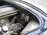
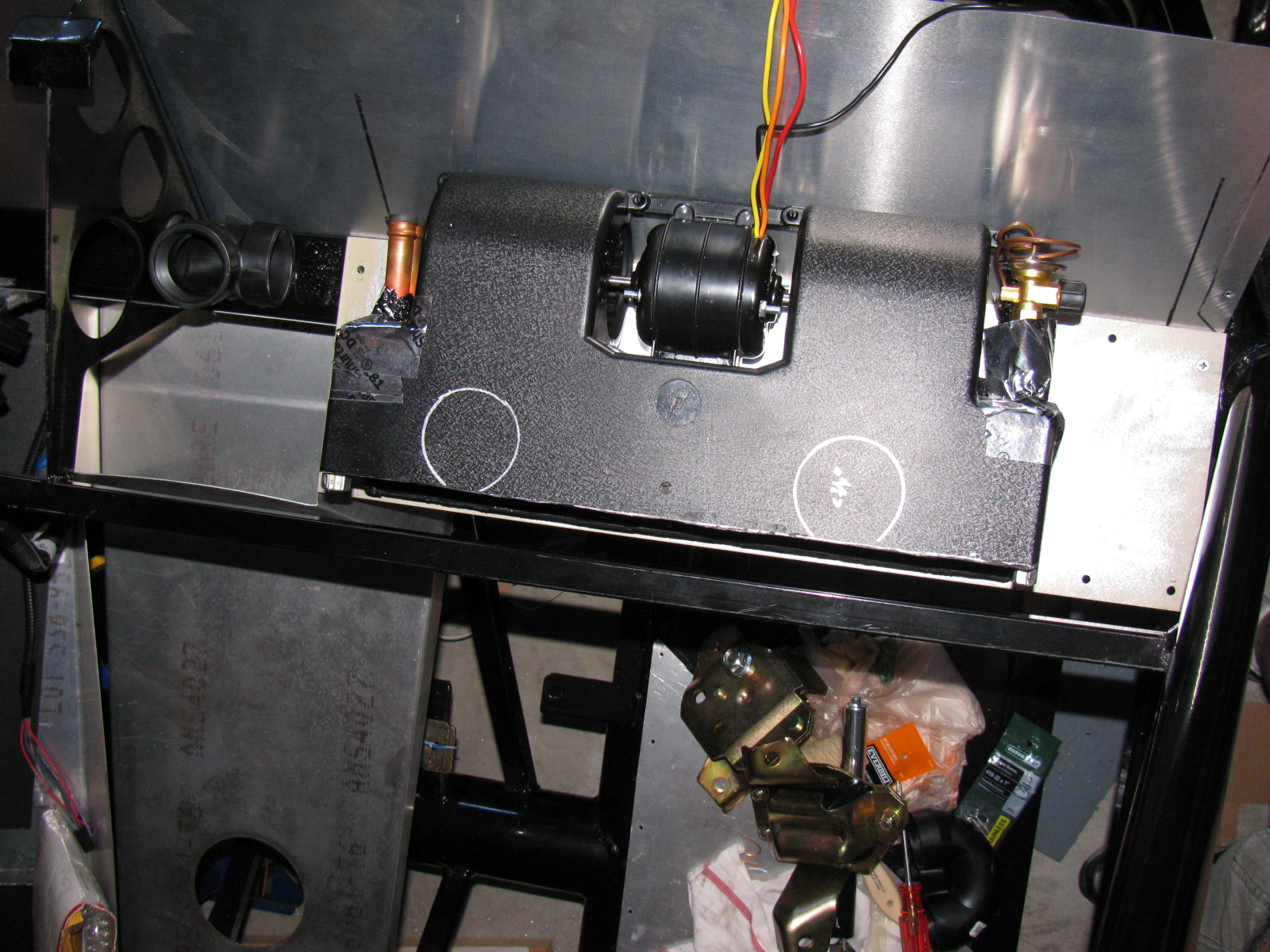
I decided to do some work on the A/C unit for the Coupe. I cut and chopped the housing cover for several hours, and then decided it might be easier to just make a whole new cover using fiberglass and resin. . . . I did some research on composites, epoxy resins, fiberglass and boat repair, and lost-foam casting. Interestingly, I am doing the same research for some stuff at work. I will try my hand at making a custom duct for the A/C unit. I have a layout in my mind, but there are a lot more things that need to go behind the dash panel besides the A/C ducts. The new cover/duct will have to make several 90- and 180-degree bends. I hope to avoid the use of too many fittings by making a single duct/top cover for the A/C unit. Maybe it should be called a “manifold” instead.
Here are some pictures of the air conditioner and the “dry fit” of where it will mount.


I also re-installed the firewall. I had to take it off and re-paint it with a higher quality silver paint. I do not have pictures of this, but it does look better than before. The paint is “harder” than the other paint I used.
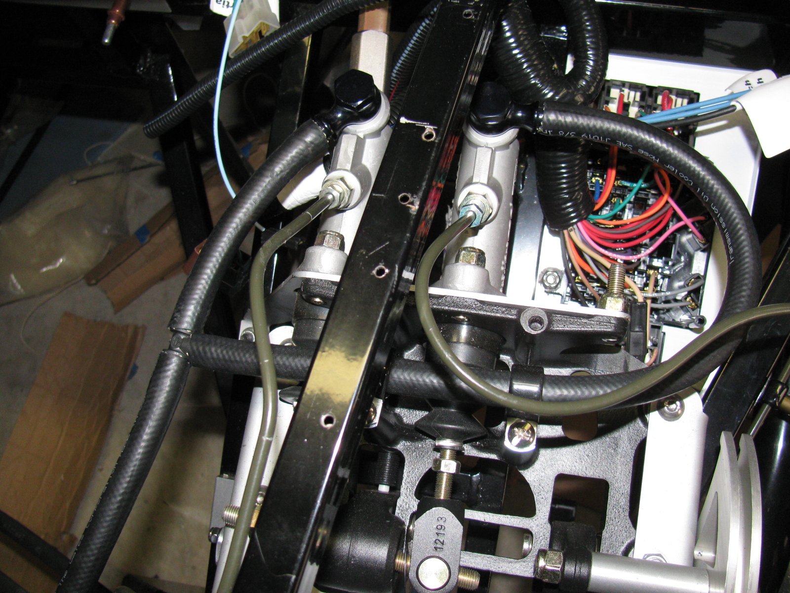
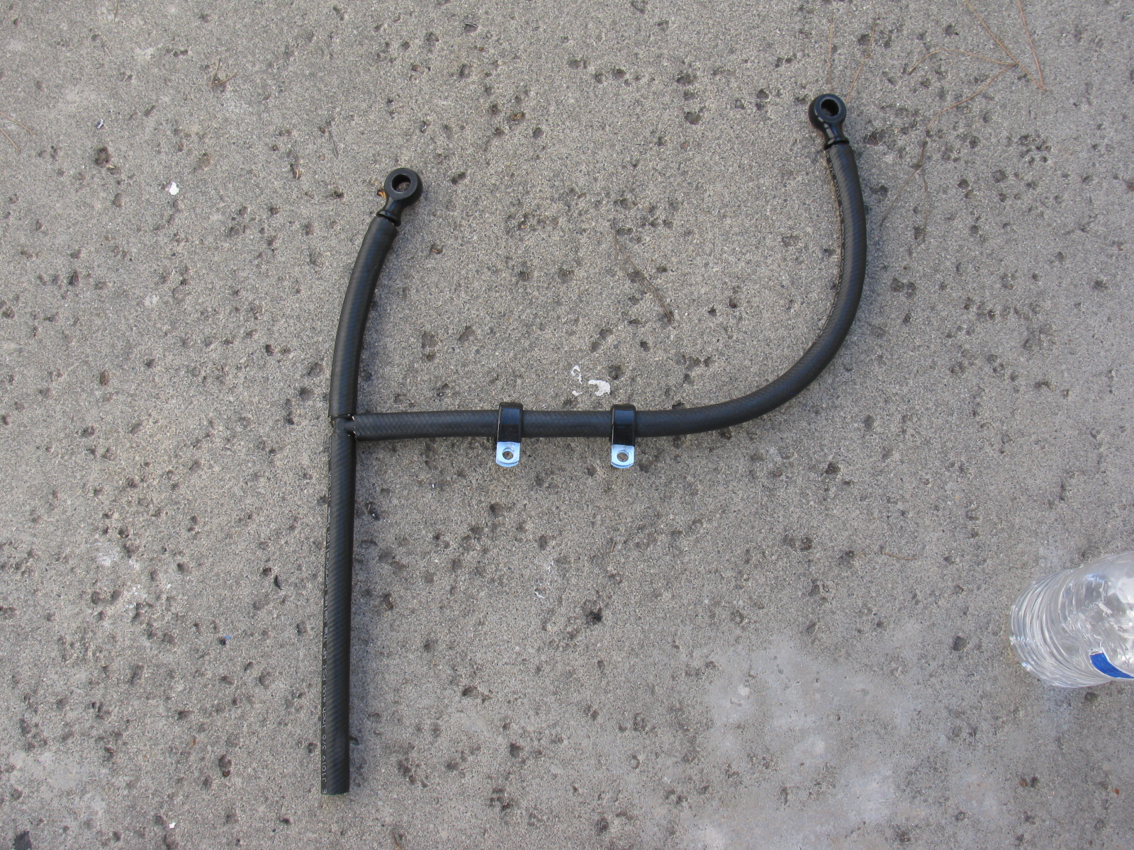
Next, I removed the “bad” brake hoses originally from the Complete Kit and replaced them with the proper red hose from the third technical bulletin from Factory Five Racing. This is the hose going from the reservoir to the master cylinders. The new hose is much softer and easily slipped over the fittings. I hope they won’t leak. We will find out soon when I fill and bleed the system.


I also started to look at engine hoist options – I want to drop the engine in SOON!
The 7th annual Factory Five Racing Cruise-In and Car show is next week! Come and see finished and almost finished classic cars – each one individually hand-built. The car show starts at 9AM and it is FREE.
Here is a video of what may have been the very last “Moment of Thunder” at the 2012 event. It is a slow pan showing some of the cars on display revving their engines all at once – a tribute to friends who are no longer with us: Roger Stine, Dick Smith, Robert Feddersen, Paul Mastroinni, and Andy Salvaggio.
The Moment of Thunder is much louder in person.
More details are posted on the Official Factory Five Racing website.
I will be there to see how others finished their Type 65 Coupe kits!

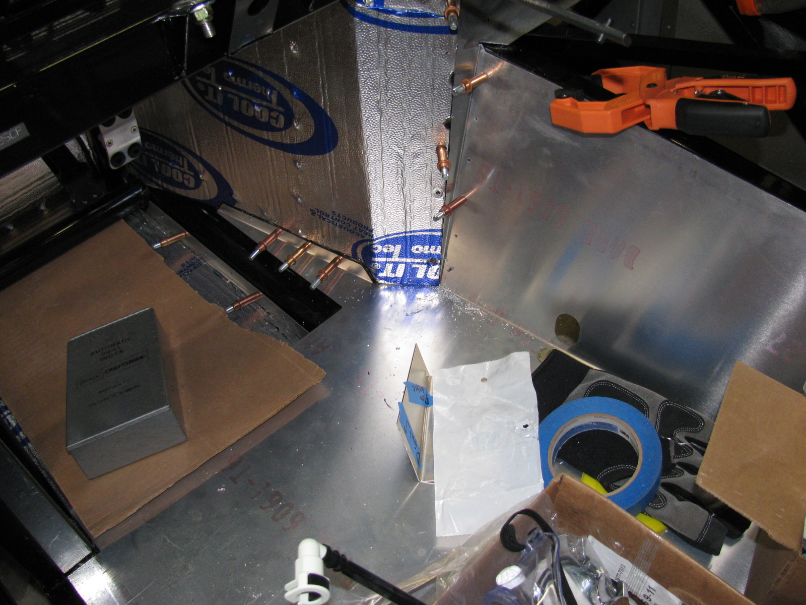
After several weeks, it is good to get back to work on the Factory Five Racing Type 65 Coupe. I finally completed drilling the rivet holes for all cockpit aluminum panels, and added a battery cut-off switch as you can see above.
Here is a hint for builders – there is a fairly large gap in the bottom right corner of the driver’s side floor and the “A” shaped piece that meets the transmission tunnel. I looked at several Coupes and Roadsters and they all have this space. However, by pushing on the A-shaped piece from behind (under the chassis and in the engine bay) – this gap can be closed up nicely. See below. . .


But what about this area, at the rear of the driver’s side door – indicated by a piece of blue masking tape – see that gap? Does something cover this space up or do I need to fabricate a replacement panel? Both sides look the same.

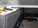
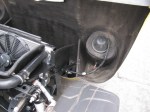
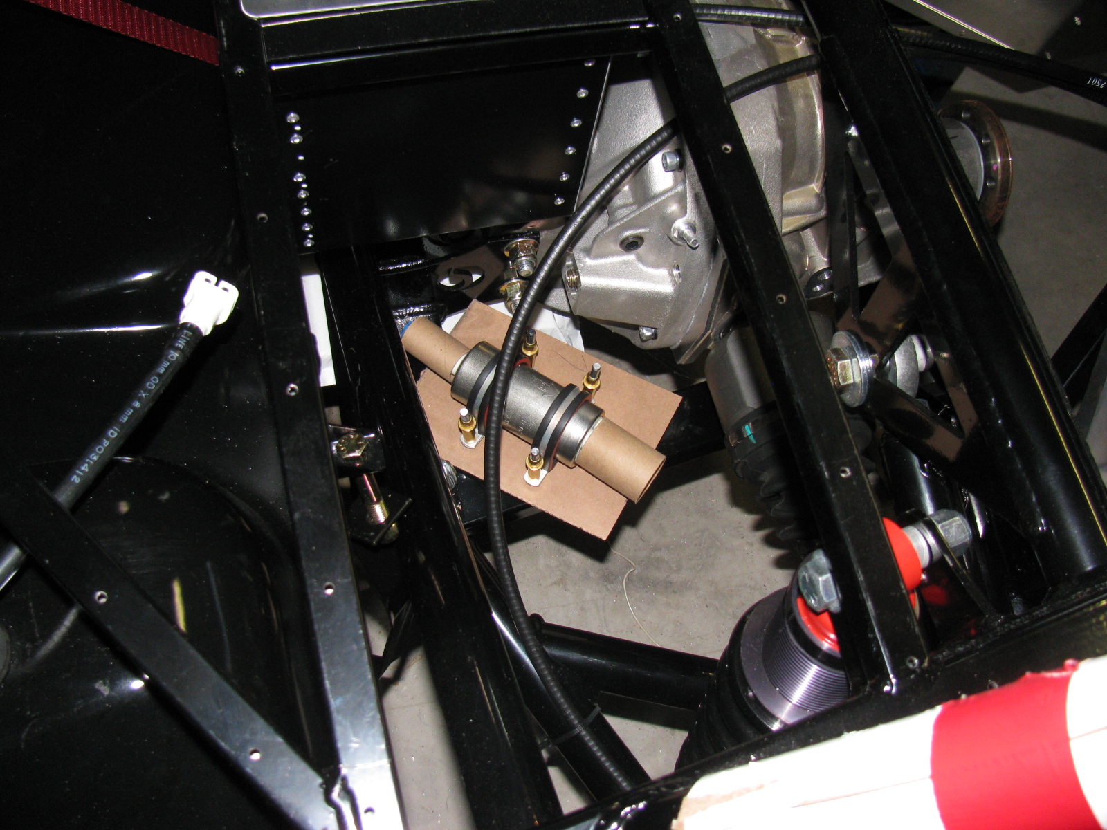
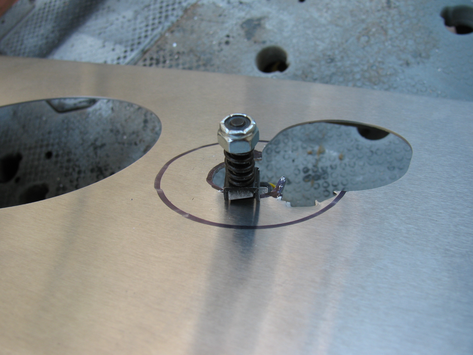
As mentioned in a previous post, I finally decided to mount the external fuel pump under the Factory Five Metal battery box. This is a protected location and is a low point on the chassis.

One problem will be access to the fill and drain holes for the Ford Racing differential. I had to drill out the rivets previously installed and tapped some 1/4-20 holes – this will enable the removal of the battery box when draining and filling the rear end fluid. Not the ideal situation, but I do not see too many alternatives to this arrangement.
My Ford 302 V8 has an MSD Atomic electronic fuel injection system, and I am running both feed and return fuel lines. Here is a picture of the tank end. . .

The fuel line runs from the first filter (right side of the chassis) to the fuel pump, and goes around to the driver side. Then it goes under the rear end to the passenger side of the chassis, where it goes to a second fuel filter mounted under the passenger seat, and finally to the engine.
The same path will be used for the return system. Pretty much standard layout.
Next Build Session
Depending on the weather, I will remove all interior panels and paint the under side with automotive under body paint. It is a rubberized black paint which should deaden some road noise, insulate heat and protect the panels from road debris.
Another item on the next to do list is the wiring harness. Here is a look at the main portion. . .

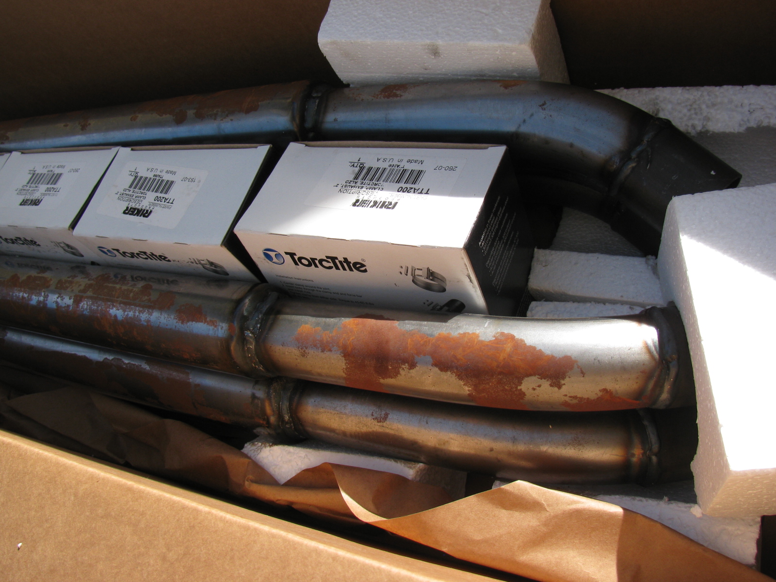
I got bored with figuring out the fuel line routing and filtering, and it was a nice warm day today, so I decided to paint the Coupe exhaust system pipes and silencers. Even though they were stored in a corner of my dining room, and were covered with oil, there was a lot of rust forming on the surface of the pipes. My kit is now a little over a year old, and I wanted to prevent further rusting.
Here is the box of pipes and associated mounting hardware from The Factory. . .

Type 65 Coupe Exhaust, Uncoated, from Factory Five Racing, after one year
There is an option to get the pipes ceramic coated, I probably should have ordered the exhaust with the coating. I noticed the brochure on the Factory Five Racing website has the exhaust listed as ceramic coated at no charge. I wonder why I missed that part?
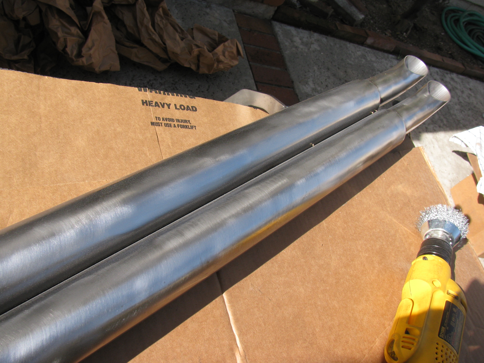
I used silver Rustoleum BBQ paint (Ultra) to finish the exhaust. But first, I prepped the pipes with wire brushes, to remove the rust and roughen up the surface, and then wiped them with acetone to degrease so the paint will stick better.

I used a wire brush on a drill motor to get the rust off and roughen the surface.

Type 65 Coupe side exhaust pipes painted with silver BBQ paint – I think it looks OK.
The BBQ paint is a bit soft, I think this is because it needs to expand and contract when heated and cooled. But it will be easy and cheap to touch up.
I am not sure what the final exhaust side pipe color will be, so I sprayed three coats of the silver on just to prevent further rusting. I may change the color to black, since I want the main body to be white.
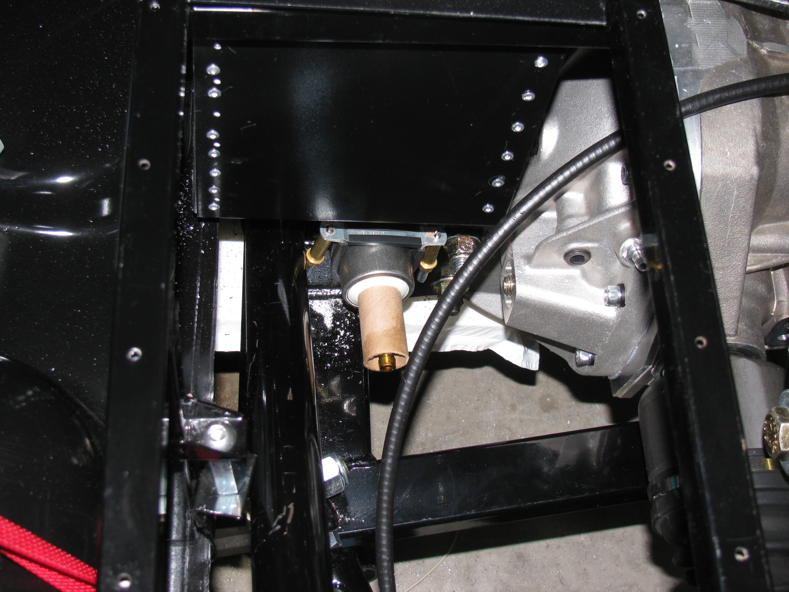
I did manage to mount the pre-filter for the fuel system. My 302 is fuel injected with an MSD Atomic EFI system, and came with most of the parts, including the fuel filters, hose, and external fuel pump. The first filter mounts where the Factory Five fuel filter is located, near the quad shock mount on the right side of the chassis. The MSD-supplied filter is smaller than the one supplied in the kit, so I had to figure out how to mount it. I am using a pair of electrical conduit clips to mount the first filter, as shown.

Electrical conduit clips are used to mount the first fuel filter to the chassis
The fuel pump will mount to the bottom of the Factory Five Metal battery box. If you have IRS and want to use the same box, you must modify the battery box slightly, as mentioned in an earlier post. In addition, you will have to figure out how to make the battery box removable, since it will block the differential filler plug.
I will be mounting the battery box with nuts and bolts, and mount it so that it can tilt upwards for access to the rear end filler plug. More details and pictures will follow when I get to that chore. Here’s a sneak peek at where the external fuel pump will be mounted.

Type 65 Coupe with IRS – battery box and external fuel pump mounting location
I should have done more homework on this part of the build process, since Factory Five Racing tells us they do not include the fuel system. This makes sense since it will depend on the engine. I have a 302 with an MSD Atomic EFI system, and it came with the (external) fuel pump and filters.
So now I have to figure out how to get from the fuel tank output tube to the first fuel filter, then to the pump and then to the EFI unit. I decided to install a return fuel line, based on the information in the MSD instructions, I hope this extra effort will be worth it.
I will make access holes and hatches for the fuel pump and filter, as well the rear suspension components and tali lights – this should make maintenance and repair easier.
Here are some pictures of the work done today.

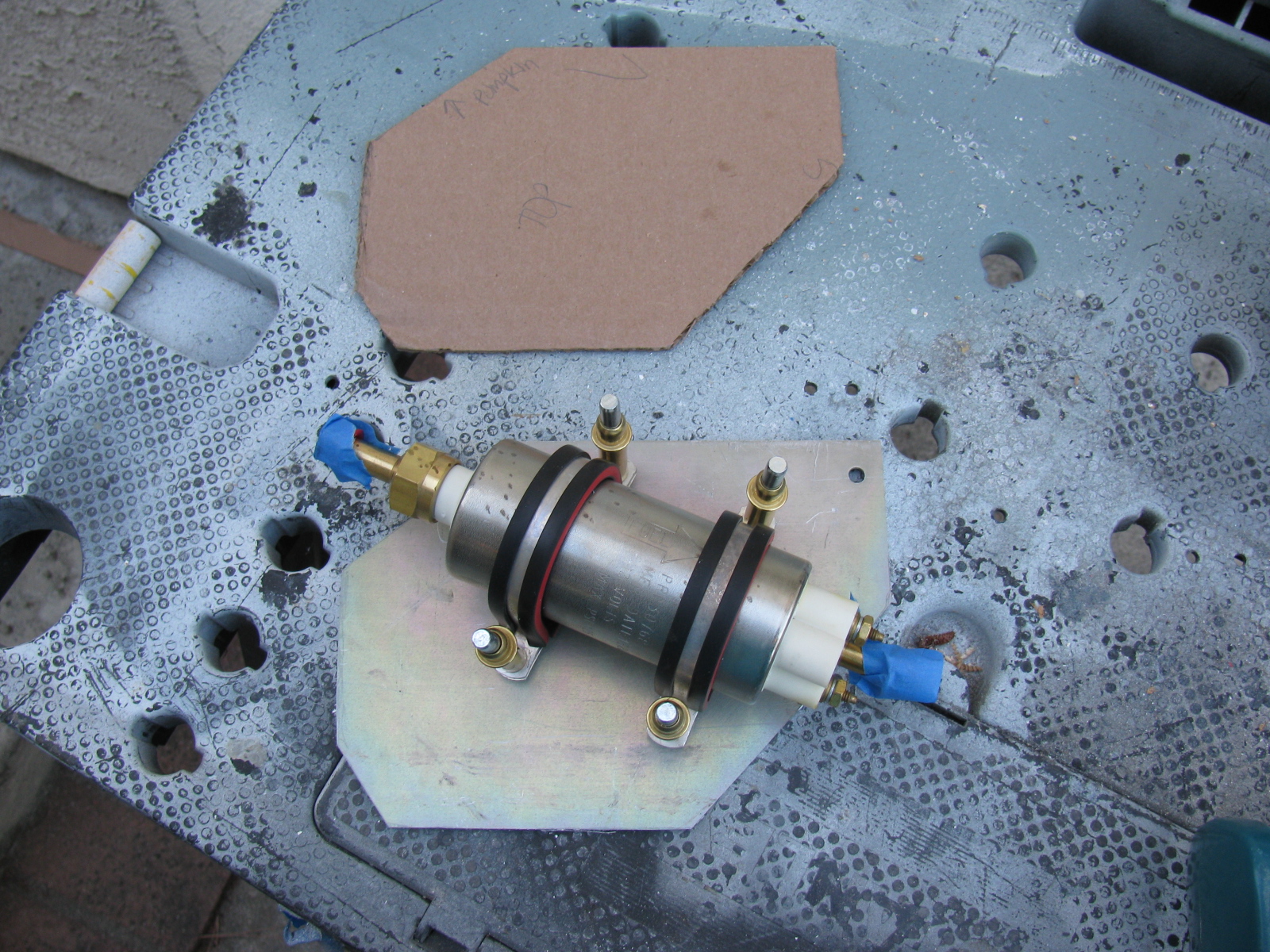
Type 65 Coupe fuel pump possible location. This is the external pump that came with the MSD Atomic EFI kit. The first fuel filter will mount to the battery box.

Using CAD – cardboard aided design, the fuel pump mounting plate is taking shape.

Here is the fuel pump in its possible location.

The cardboard template is transferred to aluminum. The mounting plate is almost a quarter-inch thick, so it will be nice and sturdy. This piece will be drilled and painted later.
By the way – the fuel tank is still not in its final location – the right side mounting bolts are not long enough. I may just get a length of all-thread and make my own bolt for that side. The left side seems to be OK. Next on the “To Do” list is fill and bleed the brake system.
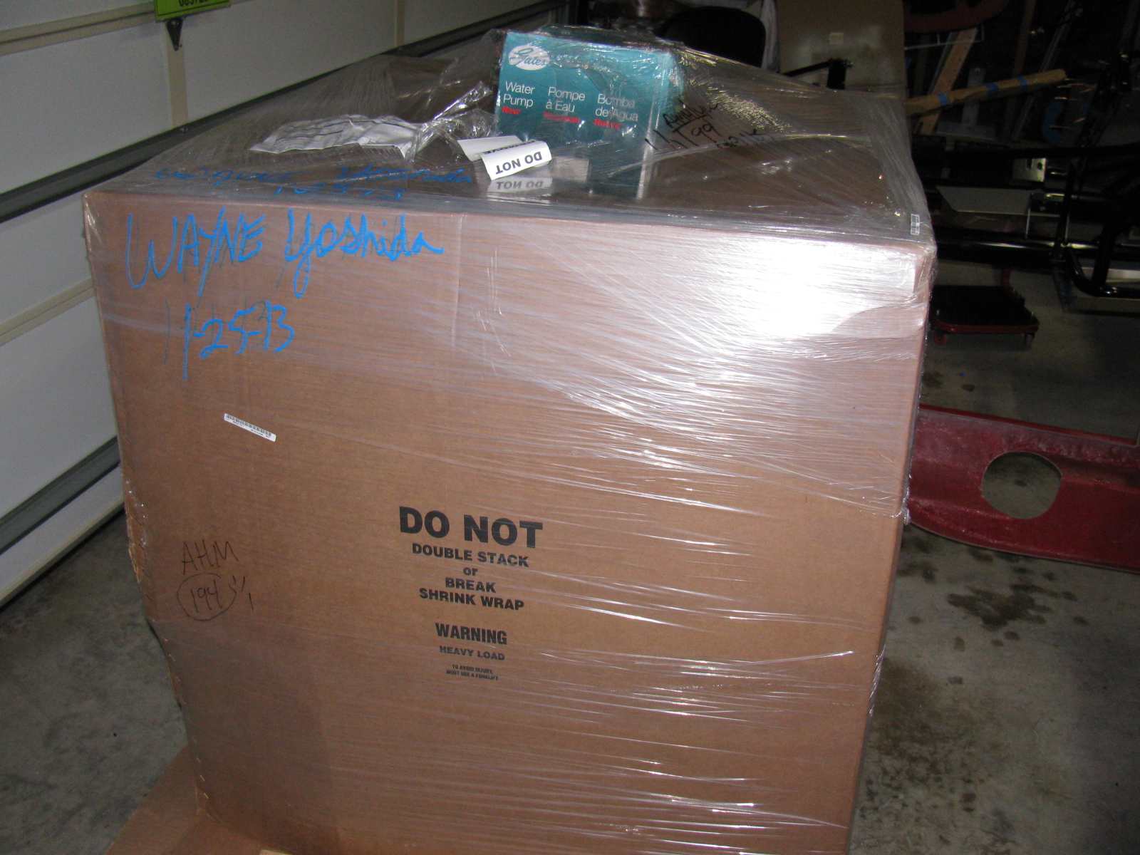
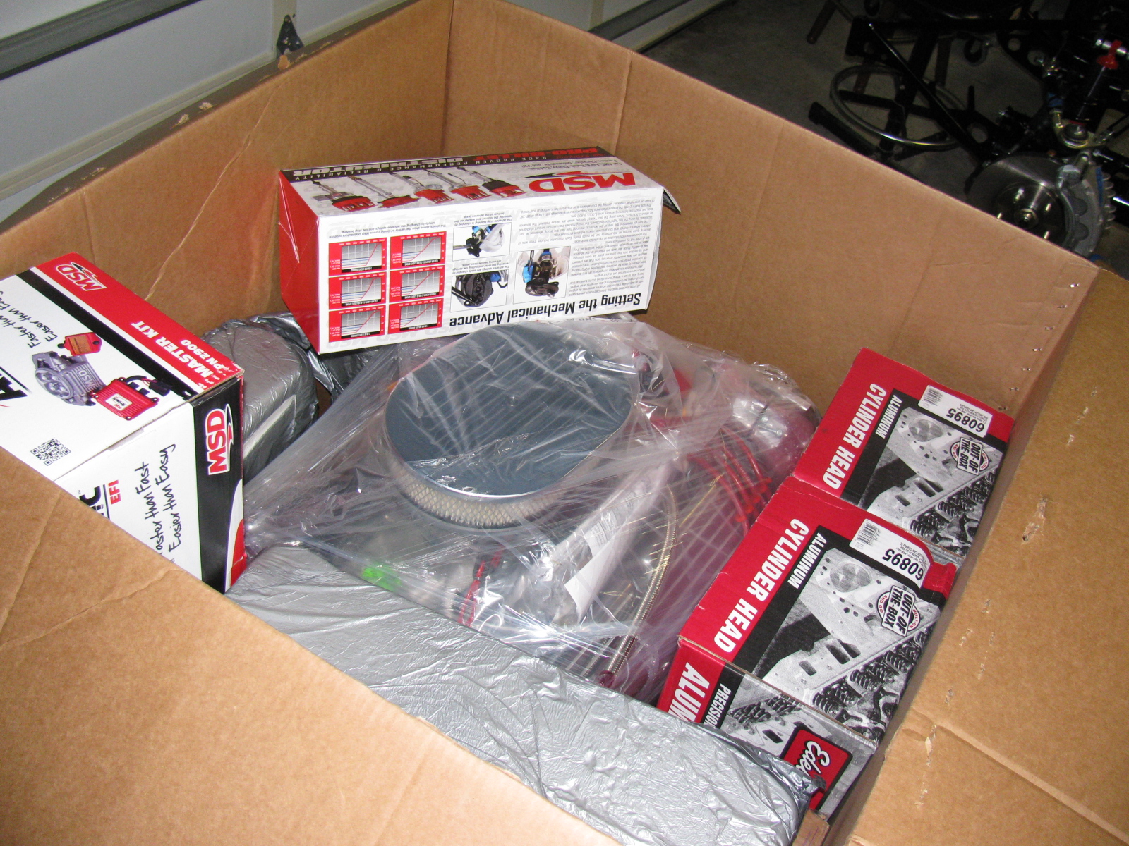
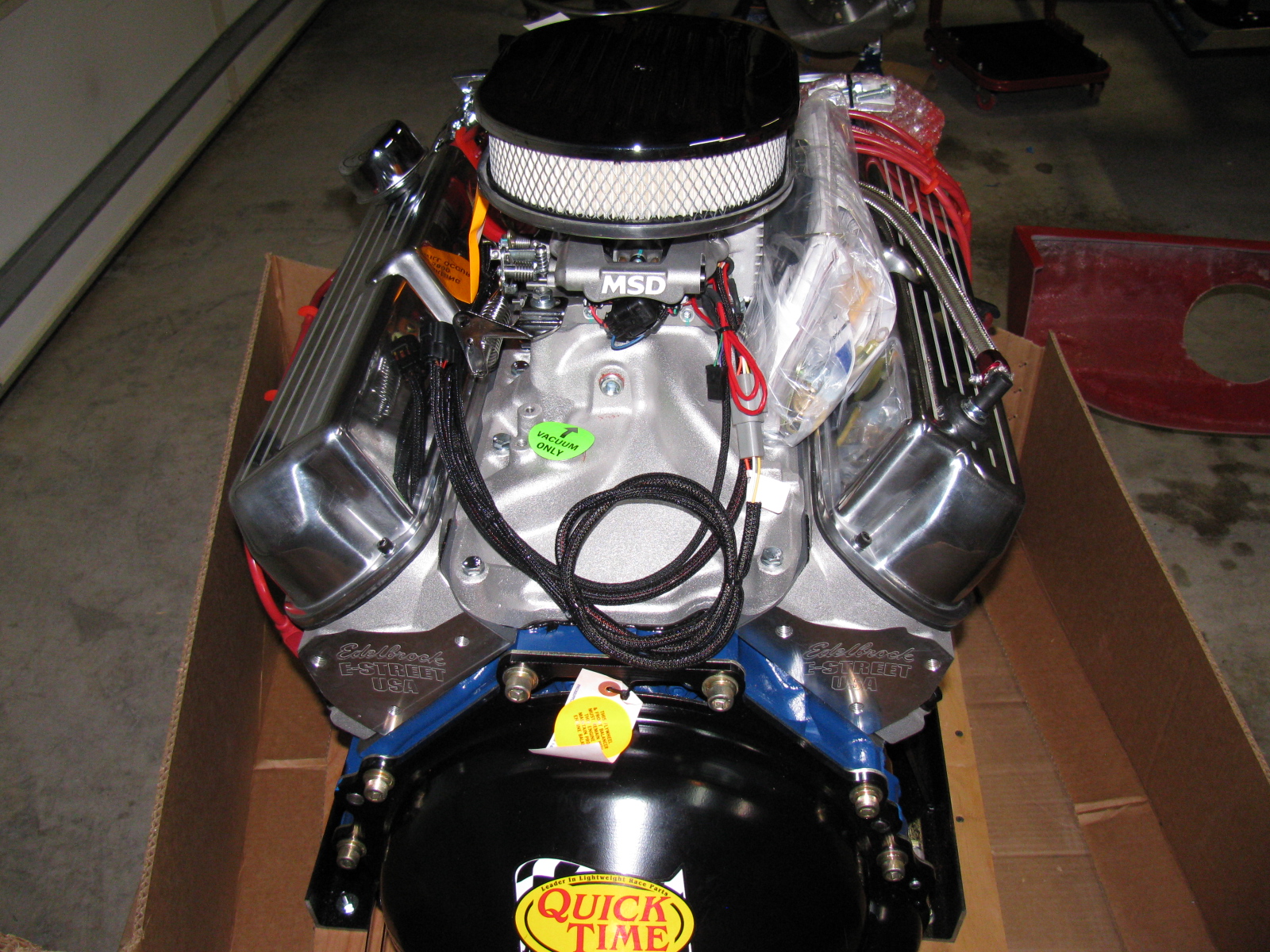
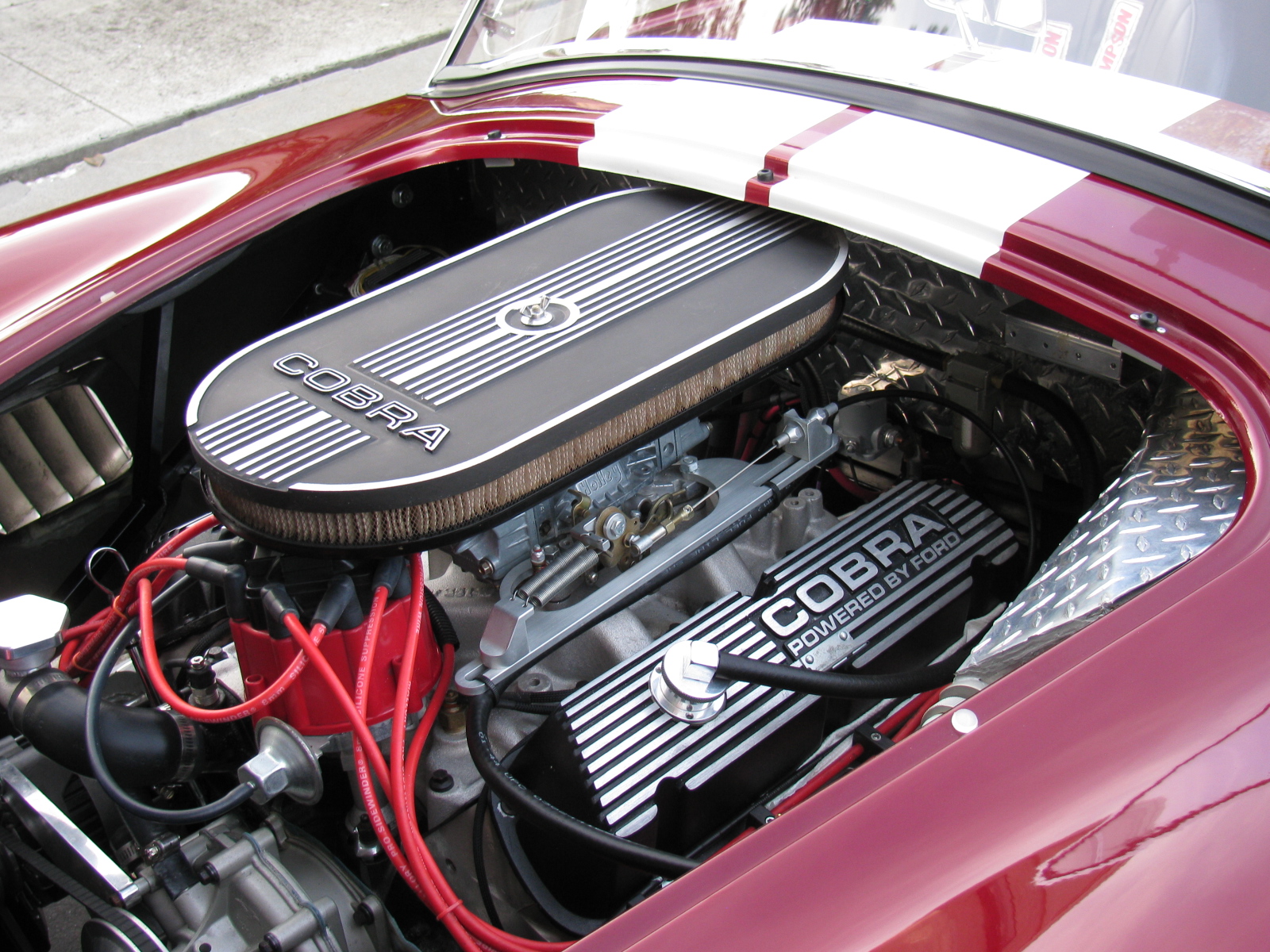
Big day today – the 302 V8 and T5Z transmission from The Engine Factory arrived. I like how everything has little tags to tell me what this thing does and where it goes.
Click here to see a video of the engine running posted on Facebook.
On with the pictures!


I am working on several things on the car at the same time. Whenever I get stuck or run into a problem, I move to a different part of the car to build. At some point, things will meet up and progress in a more orderly fashion, but at this stage, nothing is complete.
This Factory Five Racing Coupe project is consuming my life. Even when I am sleeping, I have dreams about the car, the building process or driving the car.
But lately I have been having nightmares about the car….
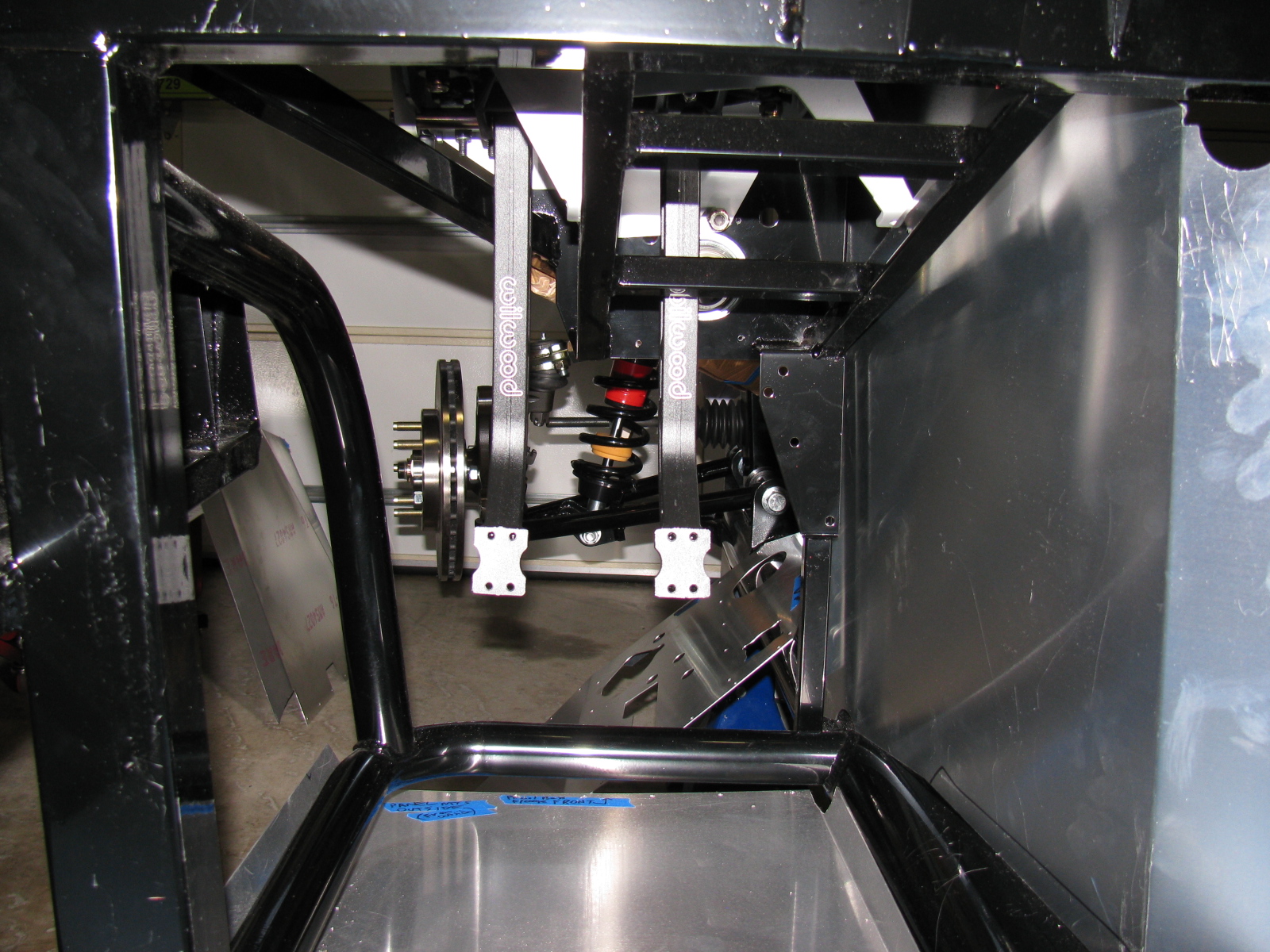
Front Suspension Re-Do
I managed to install a part on the front suspension upside down and backwards. Of course, like a lot of automotive things, in order to get to that part, a lot of other parts must be removed first. Some parts required a tremendous amount of torque to install. These are parts that should never “fall off” like anything in the front suspension and wheel mounts.
So, one of the chores I had to do was to remove the front wheel bearings and hubs. I tried to remove the mechanical lock nut with my ratchet, but it would not budge. This is a good thing, since this one nut fastens the wheel to the car. Installing these parts required several very hard whacks with my plastic hammer and several Rated R and X words and phrases. I could not help but wonder how those parts would come off if I ever needed to repair or replace them.
Reading the forums made me lose a lot of sleep, since it seems that a lot of fellow builders have had trouble with this part, too. I bought an AC-operated impact wrench and some very large (36mm) impact sockets to remove the hub nuts. As a back-up, I also bought a large 1/2-inch drive breaker bar and a piece of pipe to increase the torque if needed.
I called my friend Larry over for some assistance.

Surprisingly, the breaker bar made the hub nut come right off. Even more surprising is the condition of the spindle where the wheel and bearing mounts – it still looks brand-new and without any distortions or scratches.

After purchasing the impact wrench, Larry sent me an e-mail advising me to not use an impact wrench on the front hubs, because this may damage the wheel bearings. I took this advice, and returned the impact wrench. Good thing I did not open the box. . .
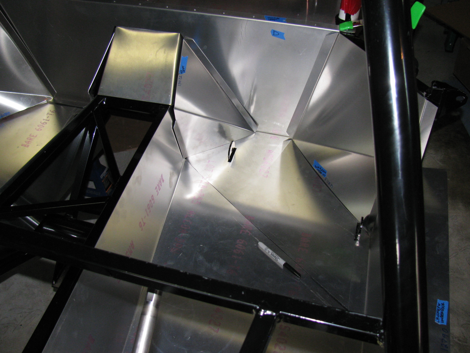
Interior (Cockpit) Aluminum Panels
After the problem with building the IFS, I decided to “dry-fit” all parts from now on. This way I can verify everything is correct – or fix things that are wrong – before tightening the parts into place.
I decided to do some more work on the interior sheet aluminum. Compared to some of the other tasks, fitting the aluminum is easy. I made some diagonal cuts along the floor to make the parts fit easier, and to prevent scratching the nearby interior panels. By cutting the single large pieces into multiple smaller pieces, they will drop into place, rather than bend and scrape into place – preserving the painted surfaces.

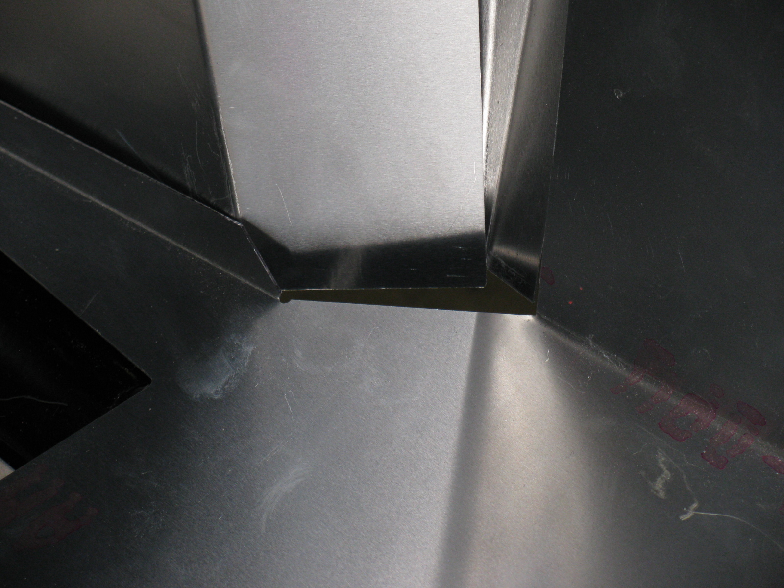
The seams and bend directions are hard to see in these pictures, the aluminum sheets do not provide enough contrast. I may use masking tape to show where the parts go and where the seams meet next time. As I said, this is the first attempt to fit the cockpit aluminum. Based on old Factory Five Racing forum posts, it looks like my aluminum panels have been improved somewhat. The only poorly fitting space is this big gap on the driver side, right at the corner of the transmission tunnel.

I may either trim the mounting tab behind one of the panels, or just install some sort of patch over the top. Overall, though, this Generation 2 Coupe seems to have better-fitting interior panels, so far.
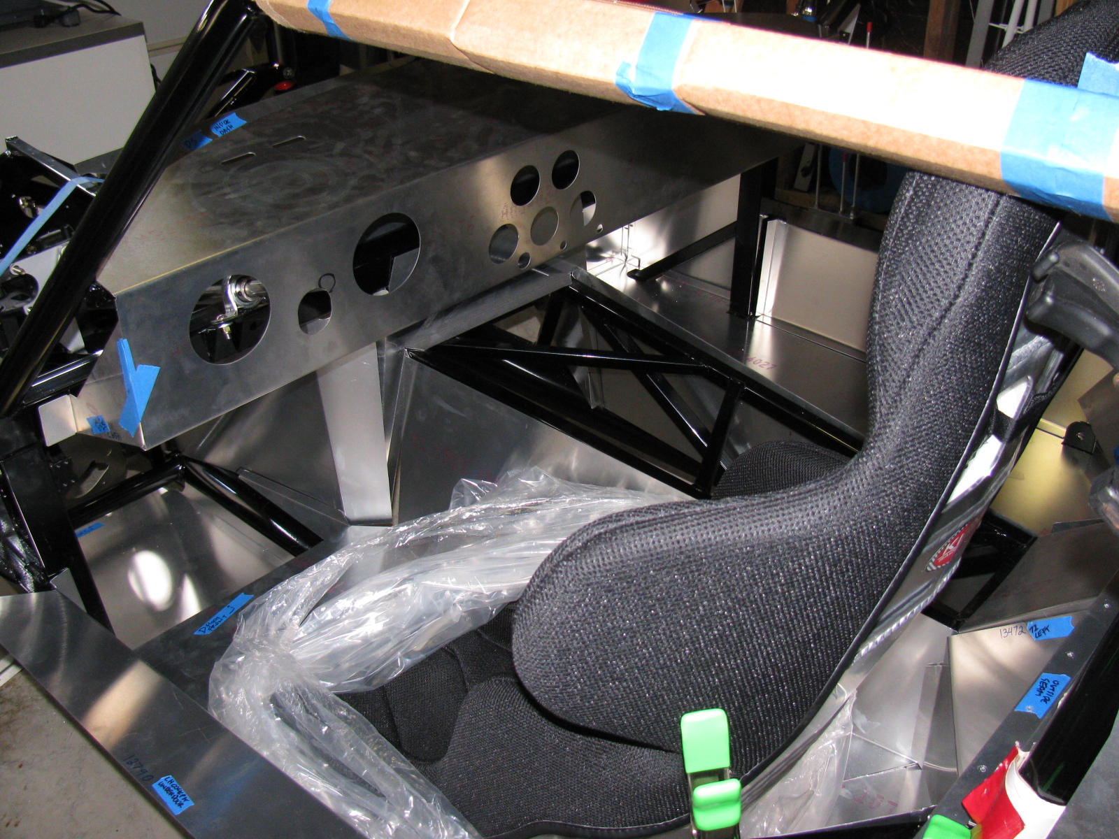
Dashboard
Here is an example of something gone wrong —

Notice the odd-shaped hole for the steering column? The mounting location for the steering shaft is not straight and parallel along the ladder structure in the driver side footbox and clutch quadrant. As I examined all the parts in this area, I believe the factory did this because of an interference issue with the brake pedal. If the steering column shaft were to run parallel to the ladder structure, it would block the brake pedal actuator. Moving the mount – but not compensating for this on the dashboard panel – makes this problem look worse than it may be.
I used a nibbling tool, a round file and a sanding drum to enlarge the hole for the steering shaft.


A popular modification to the dashboard is to cut along the bend, making the one long piece dashboard into two long pieces. This enables access to the inside of the dash from the top as well as the front, and will make installing and maintaining dash components such as gauges, air conditioner and plumbing much easier. I will make this cut at the next build session.
I just have to figure out a way to disguise the big and ugly hole in the dashboard. . .
The Racing Seats
I placed the Kirkey high-back racing seats to see how it fits, and although the steering wheel is a bit toward the passenger side, I think it will be all right.


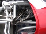
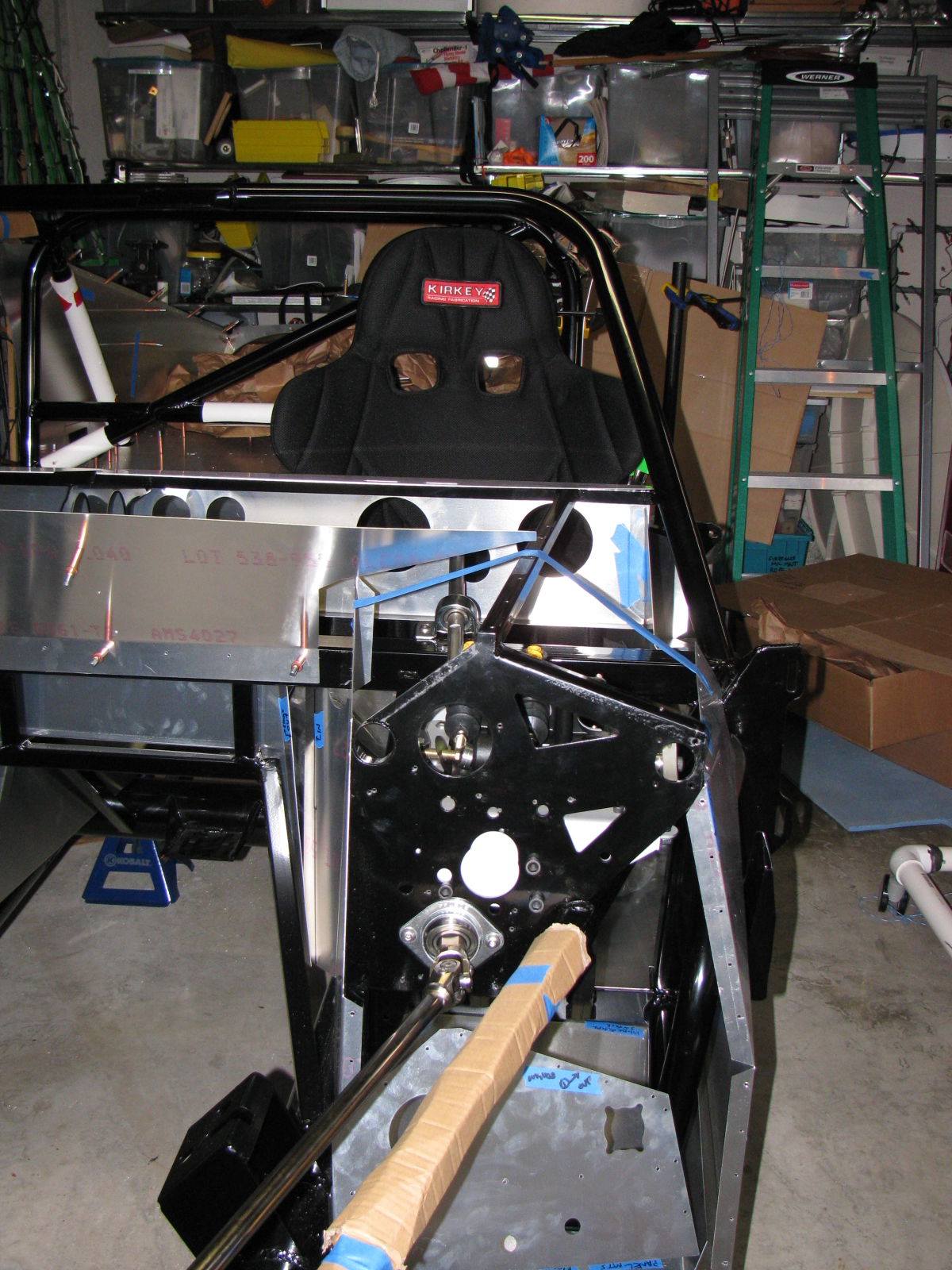
Clutch Quadrant and Pedal Box
Many Coupe builders owe a lot to a guy named Chris, who has documented his Type 65 Coupe build experience with lots of pictures. (I added a link to his flickr photostream in the Automotive Links section.) The Factory Five Racing assembly manual left an entire section out for us Complete Kit builders. There are no instructions for the Wilwood pedal box and clutch quadrant assembly. Thanks Chris for sharing your images!
Anyway – here are some pictures of my Wilwood pedal box and clutch quadrant. I do not have too many fitment issues here, except for the mounting points to the 3/4-inch tubes – I will have to wedge the mounts at the firewall in order to securely mount the pedal box to the ladder structure. I painted my footbox mounting plate with silver Rust-Oleum BBQ paint. I wanted to do a test to see how the color came out and how durable the finish is. I like the color, it is much better than the raw steel and hopefully will prevent any rust from forming inside the car.


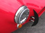
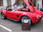
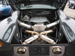
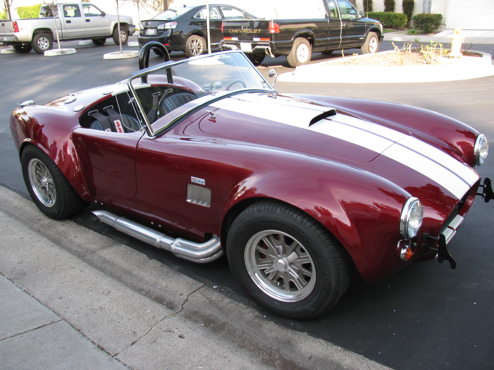
A Roadster Driver Visits
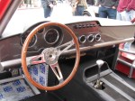
Rick, a neighbor and Roadster owner, stopped by for a visit. Here are some pictures of his very nice car. Rick did the paint job by himself in his garage – I am very impressed with the way the finish came out – take a look!


This afternoon, Bob from Stewart Transport called – the big day finally arrives – Delivery is set for Tuesday afternoon.
Two pairs of jack stands and a floor jack are needed to move the shipment into the shop – check. All ready for the delivery!
I am not going to post any “before” pictures of the garage.

I wonder if I will be able to fit the Coupe and the Prius in the garage


