Archive for the ‘rear end’ Tag
I did not do much work in the garage this past weekend, since I had to pull an all-nighter to get my CQ magazine article finished before a deadline, and there was a Coupe welcome party at a fellow Factory Five builder’s house.
Here are some pictures of a brand new Type 65 Coupe kit that recently arrived at QSL and Mrs QSL’s house. (They just finished a Factory Five Racing Roadster. It looks great and is finally registered and running.)
It was good to meet some of the other builders in the area and see the special parts QSL bought for MRS QSL’s Coupe.
Follow the Casey Family Coupe Thread for the latest updates on Mike and Julie’s Type 65 Coupe.


I took a nap shortly after I got home, lack of sleep from the all-night writing session before wore me out. I woke up, and it was dark outside, so I just went back to sleep, and woke up at 3AM on Sunday.
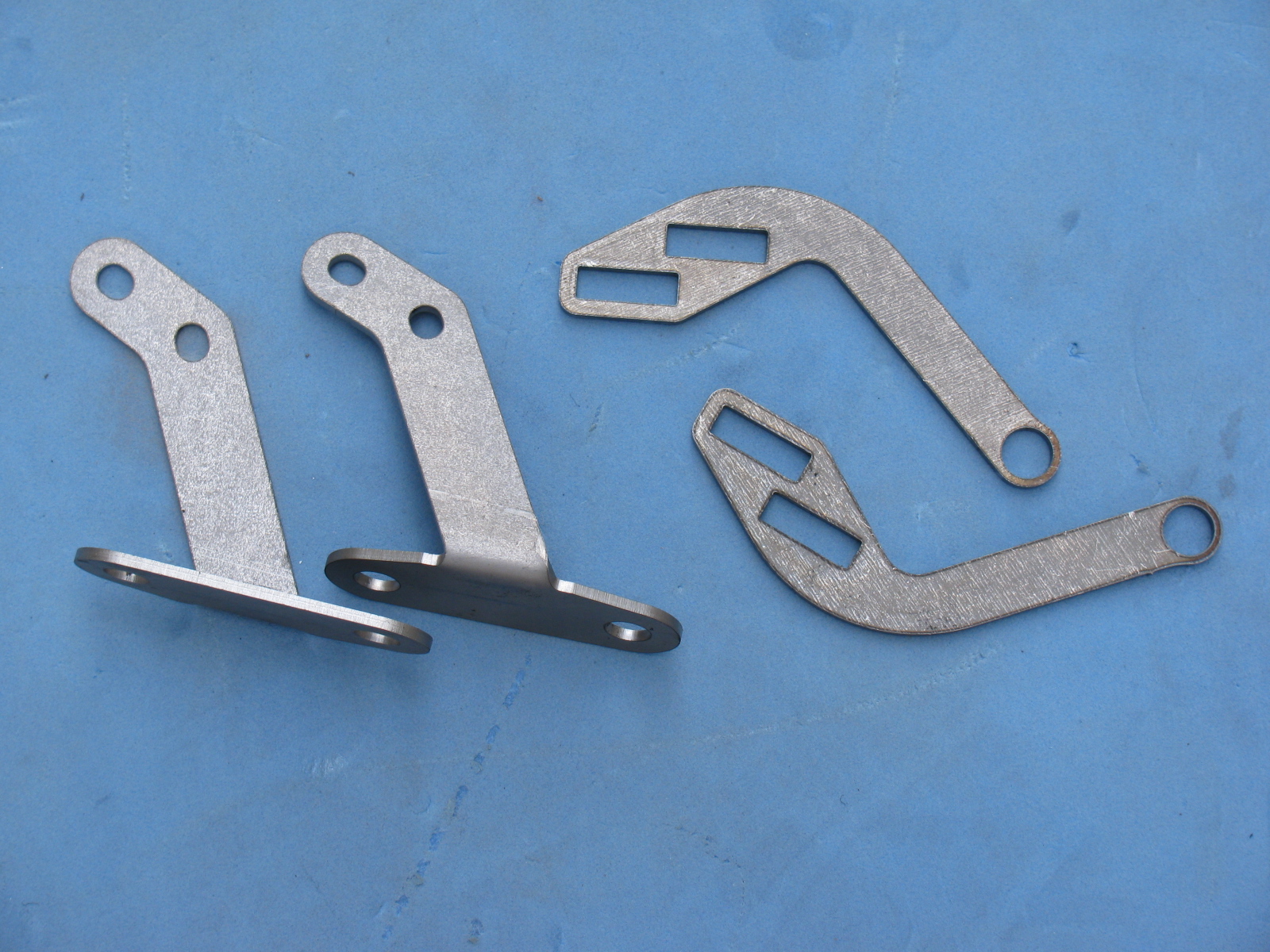
After doing some chores around the house, I decided to prep and paint the other steel parts on the Coupe. Here are some before and after pictures of the steel items painted with gloss black Rust-Oleum Appliance Epoxy. It is a great finish, and looks almost like black powder coat.


For some reason I didn’t take a picture of the hatch hinge parts or the door frame after painting. Oh well.
Hopefully will be able to get some more work done on the chassis and the rear suspension in particular next time.
Stay tuned for more. . . .
It has been raining off and on all week, and continued through this past weekend. This is a good thing, since I can avoid yard work, and even better – I can spend more time in the garage. However, the garage has been cold, 40 degrees F. This pretty much kills any plans for painting anything.
Since the 80 pound metal medicine ball – also known as the pumpkin, center section, differential and other names – is re-sealed and mounted, the rest of the independent rear suspension assembly is going smoothly.
Learning something from the front suspension experience, I decided to assemble all the pieces on one side of the car first, and only hand-tighten the fasteners. This will prevent time-consuming error-fixing.
There is a saying on the Factory Five Forums – it goes something like, “if there aren’t any pictures, it didn’t happen.”
So, since there aren’t any pictures of the parts I installed backwards, it didn’t happen, right?
Let’s just say the assembly manual lacks good pictures to help us understand how to orient things properly. Many of the pictures are cropped too tightly, and do not show the nearby parts to help us visualize relationships to other parts or reference points.
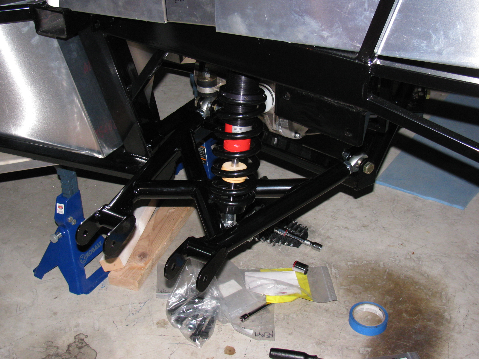
Here are some pictures of the driver side lower control arm and coil-over-shock being installed. . .


While mounting the lower control arms, I kept dropping a stack of small shims (they look like thin washers) needed between the chassis mounting tabs. Of course, since they are round, they roll all over and under the strangest places. I had to use a small magnet to retrieve several of them.
The magnet made me think of a great way to hold and install these small shims on the mounts. Take a look. . .

The little magnet holds the stack of shims together, and by wiggling, pushing and pulling on the suspension parts, the bolt will slide through the stack. This works great, and it makes me feel happy rather than mad while underneath the chassis.
Of course, this only works if the parts are ferrous. The aluminum spacers are another story.
The spindles, upper control arms, and CV axles are next. Stay tuned . . . .
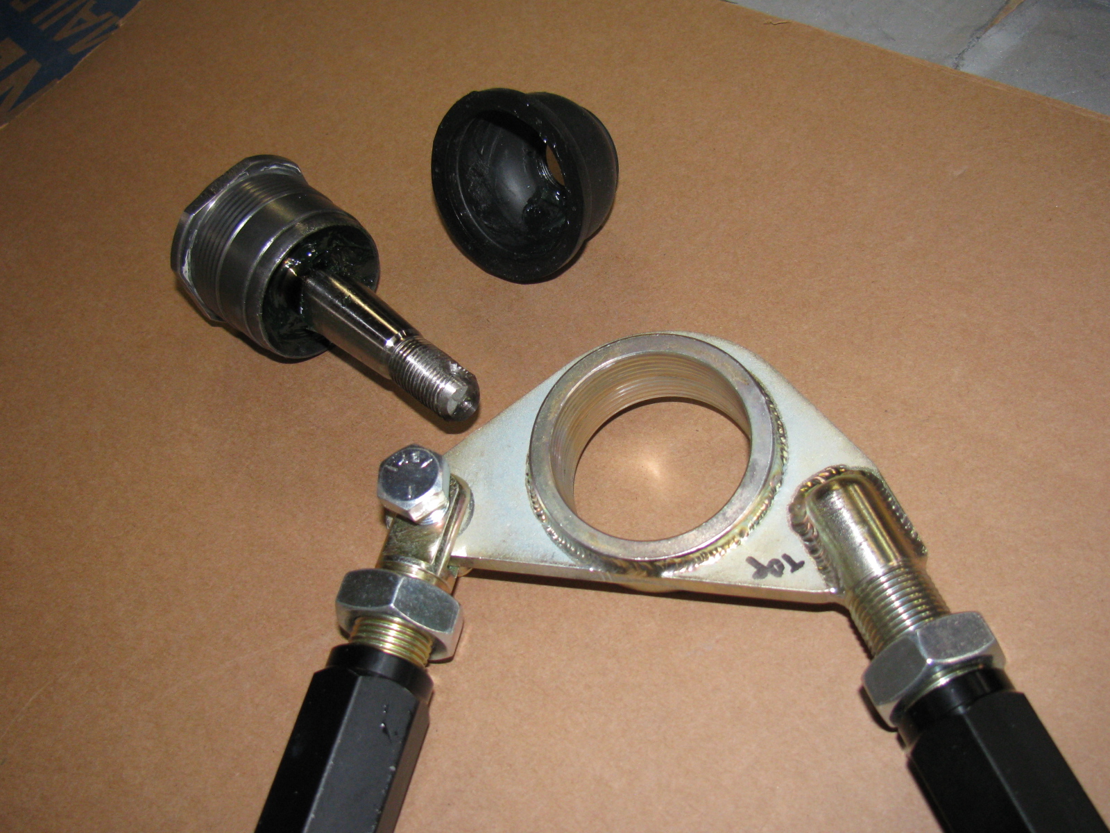
My go-to car builder friend Spider Larry once again came through for me. Using a Mapp gas torch and a piece of pipe, he separated the ball joint from the top mount for the passenger side suspension. Here are some pictures from the dis-assembly and re-assembly process on the Type 65 Coupe IFS, passenger side.


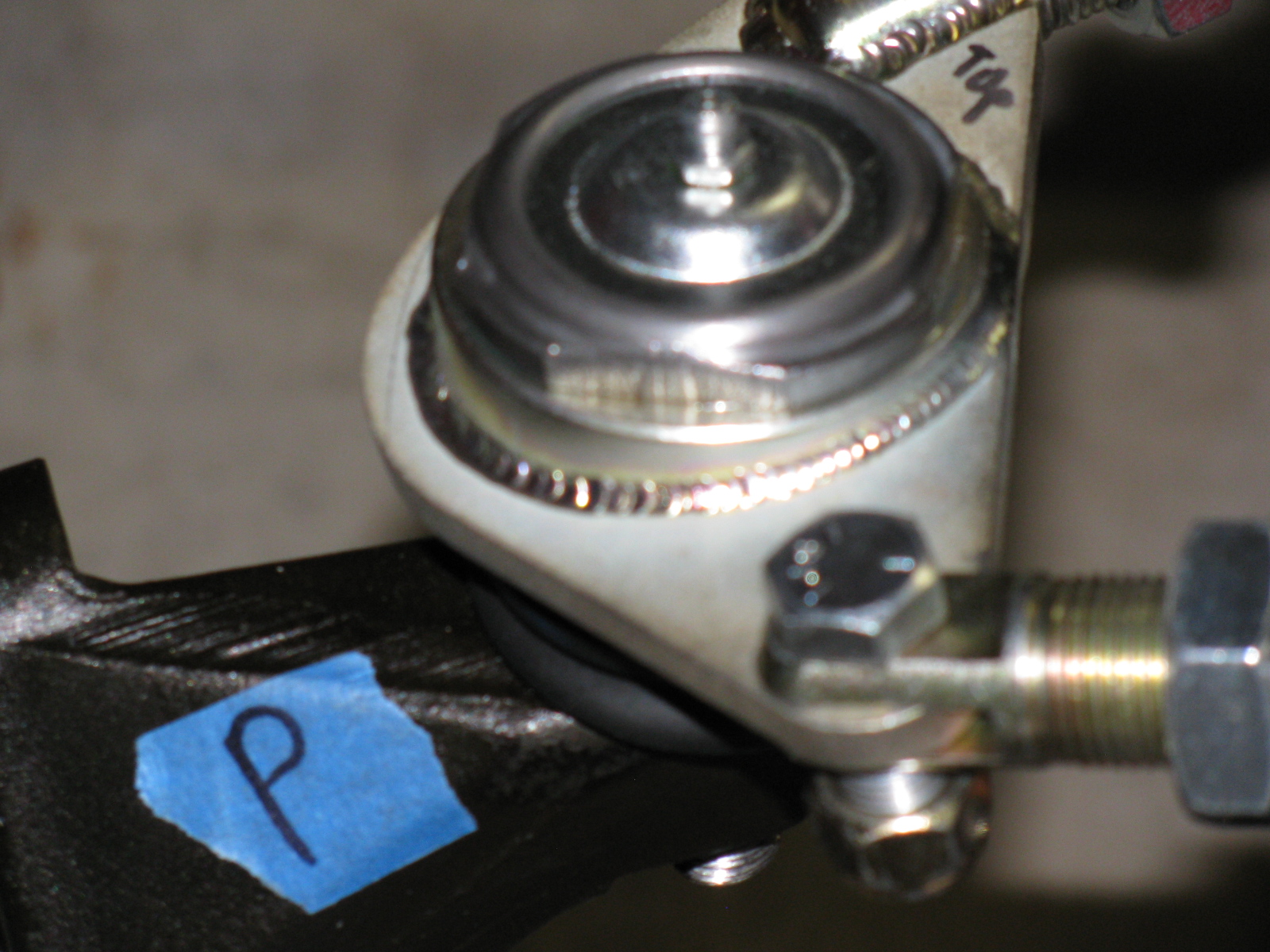
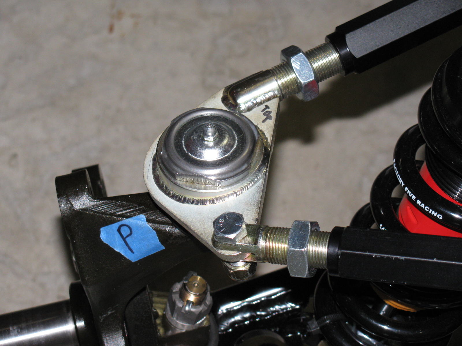
Here is the correct passenger side upper control arm and ball joint assembly:


The driver side looks like this:


So you MUST ignore the manual when it says to create a “left and a right unit with the ‘solid corner’ pointing to the front of the car.”
Footbox Heat Shields
I located, dry-fit, and drilled mounting holes for the driver and passenger footbox heatshields. The material is cookie sheet steel from the local grocery store. They have a nice rolled edge and will help deflect heat from the engine bay coming into the car interior. I am using riv-nuts and spacers to mount these sheets – er – heat shields to the footboxes.
I used BBQ paint for the shields, but may decide to powder coat the engine bay sheet metal parts, including the heat shields.
But I have to decide this quickly, since the engine is scheduled to be delivered within a few days!
Here’s the driver footbox with riv-nuts installed. All aluminum panels for the engine bay will be powder coated, the others will be painted.

Air Conditioning
Here is a picture of the air conditioner unit and where it will go. It fits behind the passenger side dashboard area, where a glovebox wold normally go. I need to allow space for the ducting and the windshield wiper mechanism, which mounts in the same area. A box to house the A/C unit will have to be fabricated.

The IRS – Independent Rear Suspension
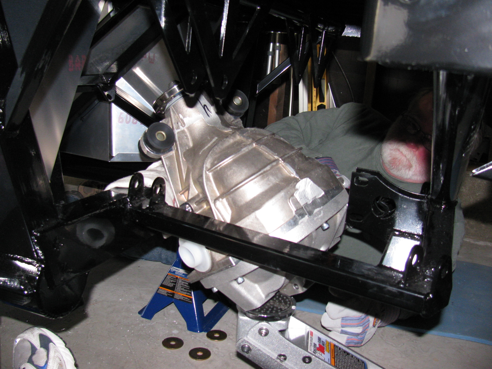
Note to builders: This procedure is quite difficult, even with a helper or two. It is highly recommended to keep small children away to protect them from hearing rated-R and -X words and phrases loudly coming from the underside of the chassis and to keep them safe from thrown objects.
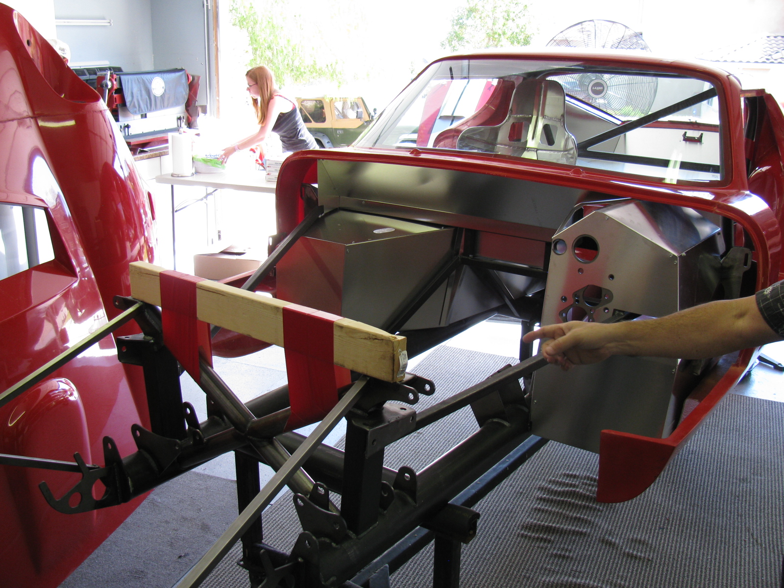
Since my ham radio friend Larry was going to stop by for a visit, I decided it would be a great time to get him to help me boost the rear differential (pumpkin) into the rear suspension cage. The Factory Five Racing assembly manual calls this unit the “IRS center section.”
There are many posts on how difficult this step is. The manual says, “It installs from the bottom with the driveshaft flange pointing straight up and the axle holes lined up front to back with the chassis.”
Err. So that means the giant 70 pound, lop-sided bowling ball like thing must be pushed up sideways, 90 degrees from the way it mounts onto the frame, and then must be twisted 90 degrees in the opposite direction to drop into place. This cannot be done safely with just one person. I found out that this is actually impossible to do with two people.
After several long hours and a phone call to Spider Larry, the pumpkin still refused to go into place.
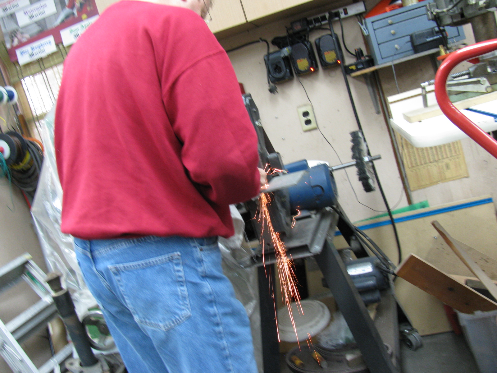
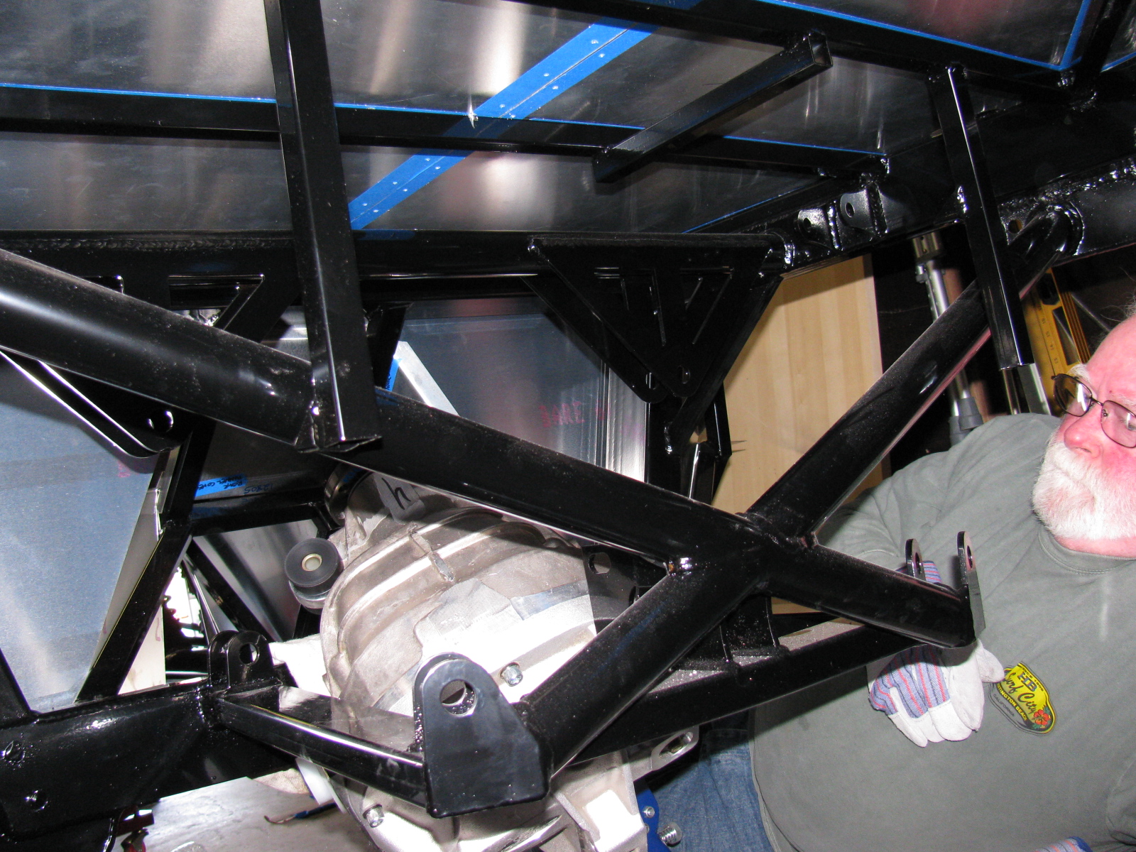
I began to think about getting a grinder and removing any offending protrusions on the differential case and chassis to make this thing fit. My ham friend Larry had to leave, but a neighbor showed up, who also happened to be a car builder. I put Phil to work right away…
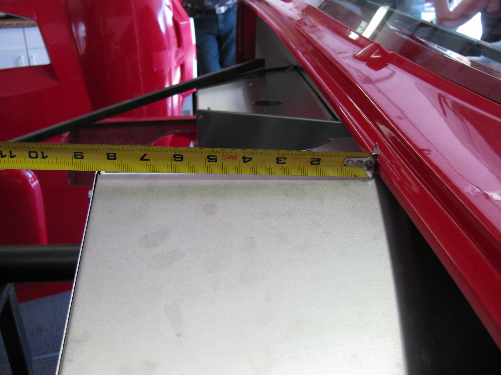
We tried a different route, maybe through the X-member at the rear of the chassis could work. So we used the jack to lift the differential high enough to check. We made a few measurements. No way.
We measured again, and noticed that no matter how you turn this pumpkin, it will not fit past the rear cover mounting plates.
We decided to remove the rear cover.
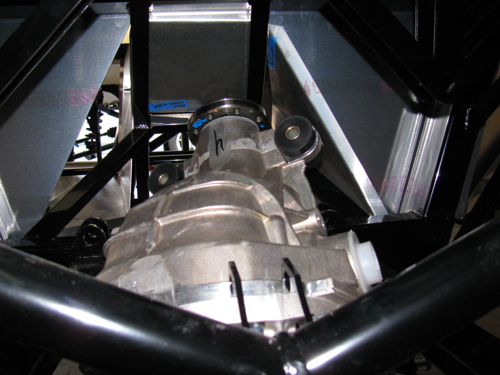
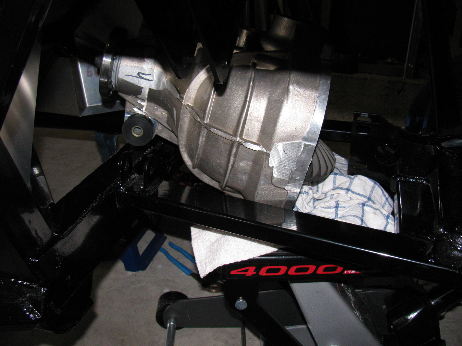
After unscrewing ten Allen bolts, and giving the rear cover a light tap with a rubber mallet, the cover popped off, very much like breaking an egg. To gain another inch of clearance, we removed the two plastic dust caps from the axle holes. Verifying that the diff does NOT have to come apart to mount the rear brakes, we put it back on the jack. Modifying the instructions, we lifted it with the driveshaft flange pointing up and the axle holes at a 45 degree (not 90 degree) angle, and pumped the jack. Now it went past the offending rear mounting plates, and into place.
Of course, now the differential must be re-sealed, so we tried a dry run with the rear cover. Yes, this will work. I currently have the pumpkin suspended above the mounting location, held in place with the jack, a 2×4, and a nylon strap. I will finish mounting this beast at the next build session.
Here are lots of pictures of the wrong way to do this. A video of this procedure would be most helpful, but I am sure most builders will have enough in their hands to not have a camera operator getting in the way.


So – take my advice, save at least 6 hours and lots of non-child-approved words and thrown objects, and remove the differential rear cover before you install your IRS center section. . . .


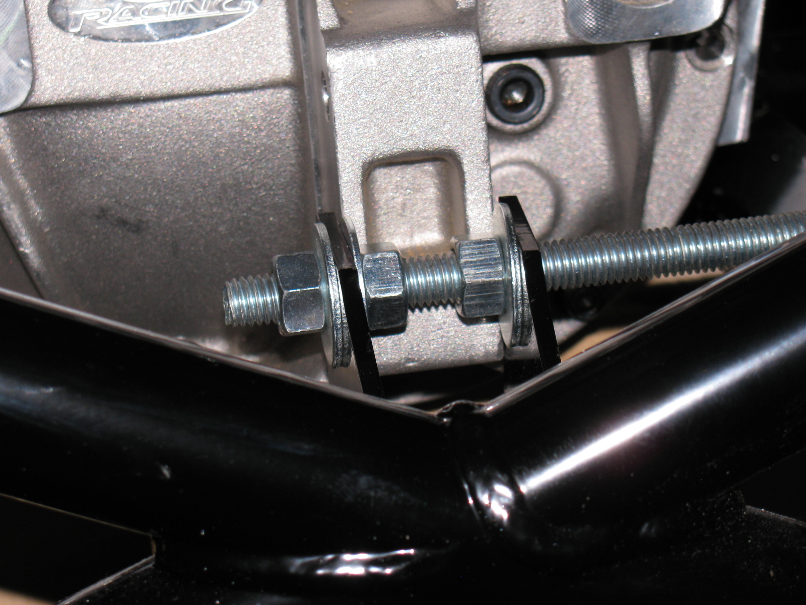
The rear mounting tabs (with the nice “5” logo laser-cut into them) are too close – use the threaded rod-expander trick to make it fit.
By the way – anyone else missing two nuts and bolts for the pumpkin mount? My parts list is correct, and yet I am still missing two fasteners for the standard width IRS differential.

I discovered I have the wrong adapter plates for the rear disc brakes, These are for the non-IRS version of the car. Jason at The Factory is sending the correct parts to me……

I planned on doing more front end work this past weekend, including the installation of the steering rack, since I keep kicking that awkwardly long box on the garage floor. Then I wanted to move to the rear suspension, since the CV axles are finally on the way.
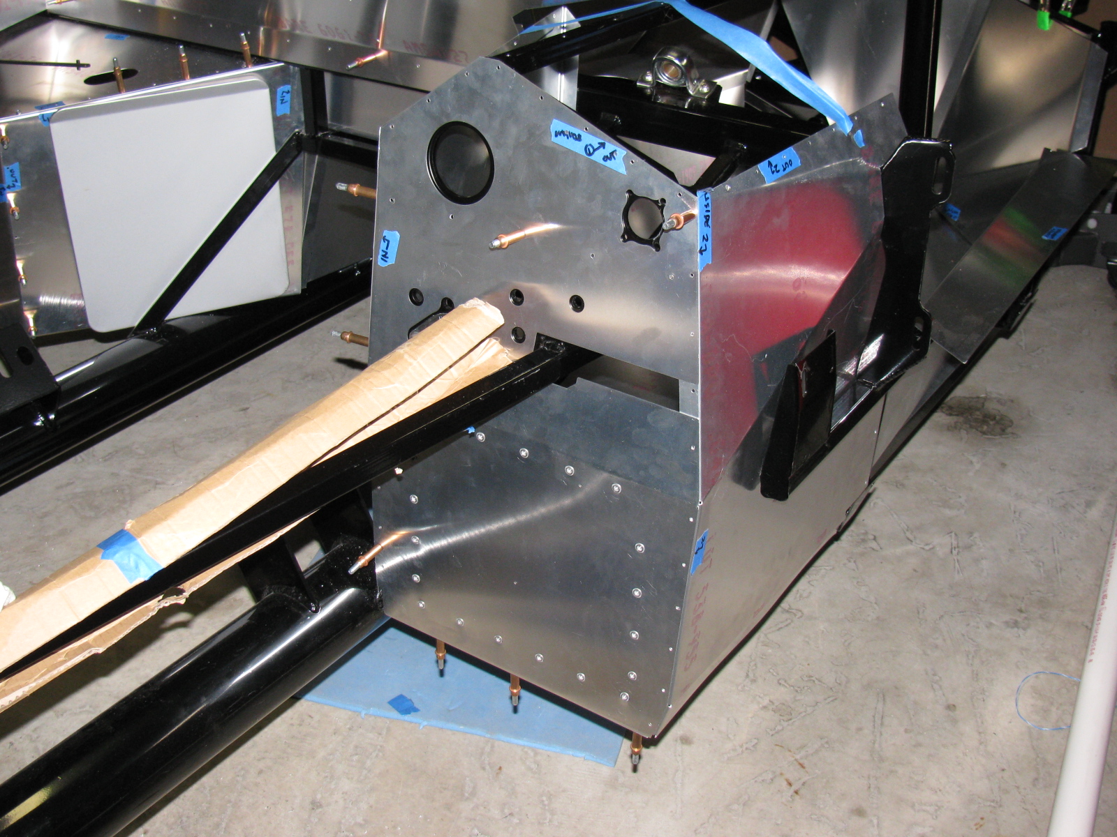
But as I thought about doing the work on the rear end, I decided to start drilling and fitting the rear trunk aluminum sheets. I wanted to avoid dropping aluminum and steel debris onto the new suspension and drivetrain components.
I want to drill and fit, not fasten and mount these panels, because they will be painted or powder coated later. This is always a messy and time-consuming task, and in the Coupe, a lot of the panels will be visible. Someone on one of the Factory Five forums said that if you count the number of holes you have to drill, you will lose the will to live. Funny. And true. Here are some pictures of the trunk aluminum.

Over all view of the Coupe trunk area. I used lots of Clecos on the back seam, because I had to pull the aluminum sheet on the rear panel tight against the floor.

The blue tape in this area is for a removable hatch to enable access for rear tail lights and the wiring harness. Better do that modification now, rather than later. Other access panels and storage boxes will be installed at various locations in the floor and the sides of the trunk.
I should draft a construction plan for this project, since I am almost randomly moving through the assembly manual.
My vintage-style Halibrand wheels still have not arrived, and I am missing some brake system fittings. When those parts arrive, I will have all the ingredients for the Factory Five Racing Type 65 Coupe Complete Kit. The engine and transmission should be done soon, delivery is sometime this month.
Having things from Factory Five on back order is not so bad. It just means that packages arrive every now and then, and it is sort of like having gifts to open and see. For example, earlier this week, the box containing the exhaust headers and rear view mirror finally came back to me. In addition, I received the rear brake kit and the rest of the rear end hardware and fasteners.
The headers are nicely polished aluminum and are surprisingly light for their size. It looks like they mount to the exhaust muffler assembly with these splice-connector sections. Other versions of this exhaust are joined with a flange arrangement. I am not sure if I like this method of connecting the headers to the muffler assembly. I will have to post a question on the Factory Five Forum to see what others have done.


The steering arms are still missing (FedEx tracking info indicates they are in transit and will arrive just before Thanksgiving – this is great timing, since I will have a few days off to do some more work on the car), so I cannot install the front disc brakes. The CV shafts are missing so although I can start on the rear end, I will have to stop in the middle and wait for those pieces before I complete the rear end assembly.
So, I decided to work on the aluminum panels this weekend. I marked, center-punched and drilled the driver’s side footbox first. I used my new cleco pins and pliers for this sheet metal project. I really like them – I wish we used these in Mr. Spence’s 7th grade metal shop class!


See the gap at the peak of the box? I will install a strip of thin bar stock over the entire top seam to make it look better.
Some of you are wondering – what’s a cleco? I wondered about that, too. Wikipedia says, “A cleko, also spelled cleco, is a fastener developed by the Cleveland Pneumatic Tool Company. . .”
http://en.wikipedia.org/wiki/Cleko
So the next thing you may be wondering is – why do I have to use temporary fasteners to put these sections together? Another good question. I have to trim, drill and assemble all of the sheet aluminum parts – and then take everything apart so I can de-burr the holes, remove all the marks and scuff the panels to get them ready for paint. Although some builders have left these panels un-coated and raw, I decided to apply a finish to all the panels to prevent corrosion. My plan is to paint all interior panels (except the dashboard) with silver Rust-Oleum high temperature barbecue paint. I will paint the dashboard with Gray Hammertone – a darker color than silver, and it will have a nice contrast against my AutoMeter gauges.
Everyone seems to talk about the high temperature part of this paint, but no one mentions the fact that no primer is needed. I think that is one of the best features of this paint – one less step to do.
An alternative to the BBQ paint is what I use for my electronic chassis project boxes – Rust-Oleum Appliance Epoxy. This is another paint that does not require a primer, and the stuff is pretty durable. I would use that instead, but the colors are limited to white, black and almond. Yuk. Too bad.
At least, that is the plan so far. I might change. I am also considering some color alternatives to my original plan of having a white body and black stripes. But that part is a long way off. I will make a final color selection when the Halibrand wheels arrive – they still have not shown up yet.
It looks like there are just three things missing from the kit: The front steering arms, the rear CV shafts and the Halibrand wheels. The 302 V8 and T5z transmission should be here in December – so some serious building is about to begin!


