After something like three or four false starts, I finally settled on a way to mount the external fuel pump on my Coupe. The final solution is so simple, I feel stupid….
First, I tried mounting the pump on the lower brace, under the IRS pumpkin. But that just did not look right, and it was difficult to access from either above or below the car. Then I tried mounting the pump on the Factory Five Metal battery box, but discovered the battery box blocks access to the fill and drain plugs on the differential.
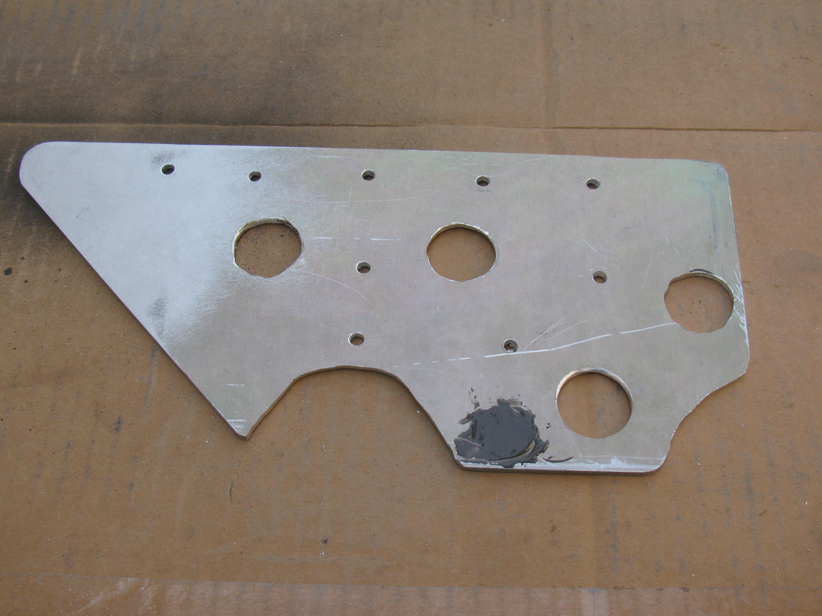
Here is the final answer, a simple, flat plate of 1/8-inch aluminum. This will help simplify the fuel hose routing, too.

More Fabrication
I made a pair of triangular plates to create a bulkhead to hold the e-brake cable and the fuel hoses (one for supply to the engine and one for the return into the tank) on the passenger side of the chassis. An identical plate for the driver side will be used for the other e-brake cable and any wiring harness going to the rear of the car.
Since the 1/8-inch aluminum plate I am using for these brackets is scrap material, some extra holes are sometimes included in the items I make. When I am not able to re-use existing holes, I patch them with JB Weld or epoxy, then paint the item with high temperature BBQ paint. These brackets are finished in silver.
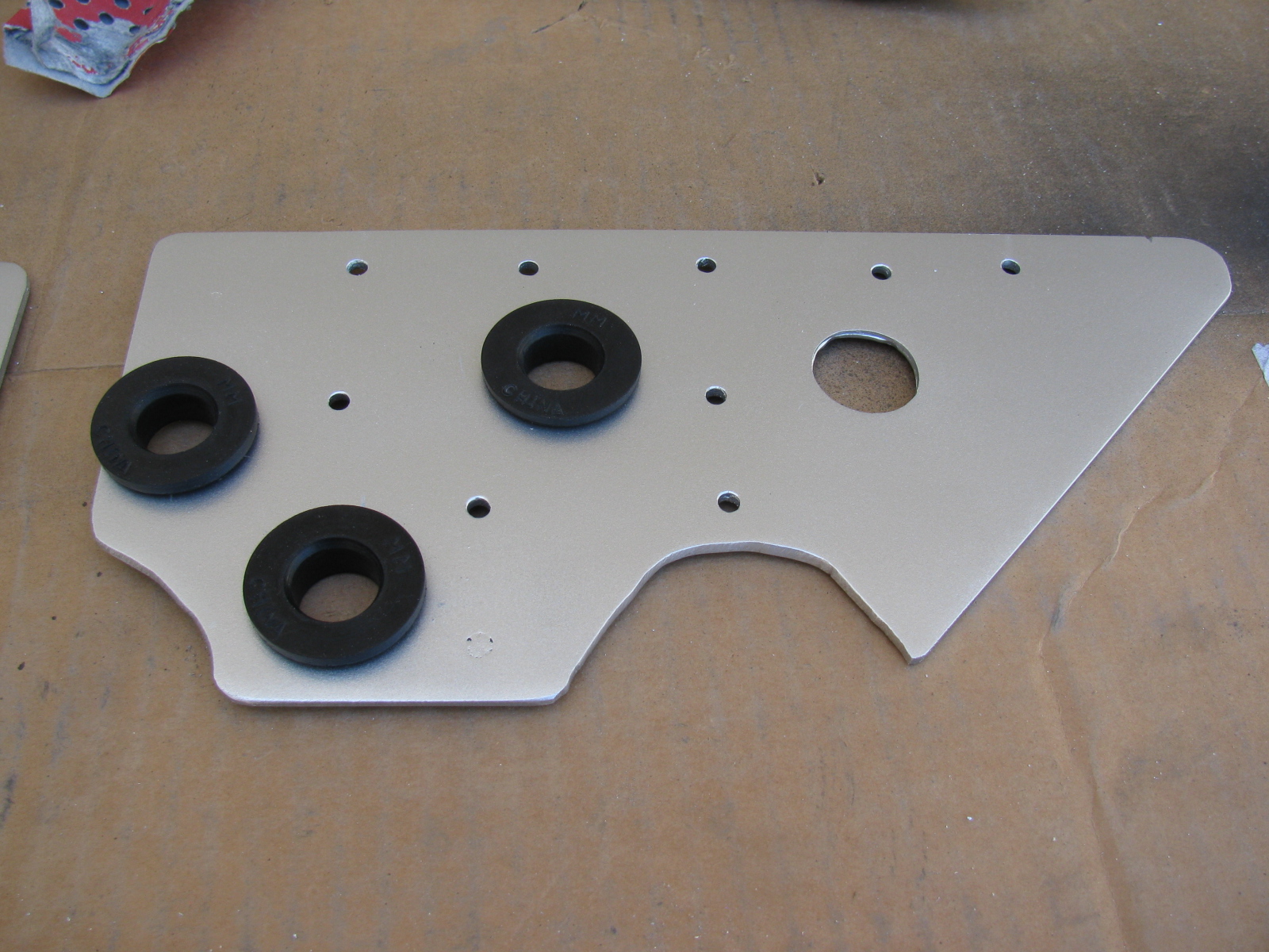
The large holes are cushioned with a PCV grommet; it is thick and large enough to pass the 3/8-inch fuel lines nicely.
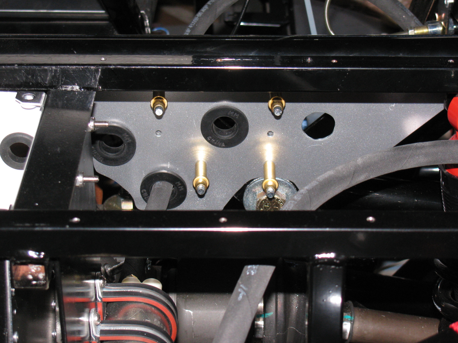
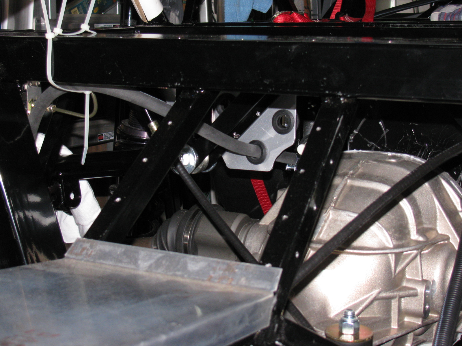
Here are some views of the passenger-side bracket installed with Clecos:
Next, I started laying out the e-brake cables and the complete kit e-brake handle. When I installed the rear brakes, I thought the cables looked too short. And last night I noticed that I am correct – the cables supplied with the IRS brake kit are about four to six inches too short.
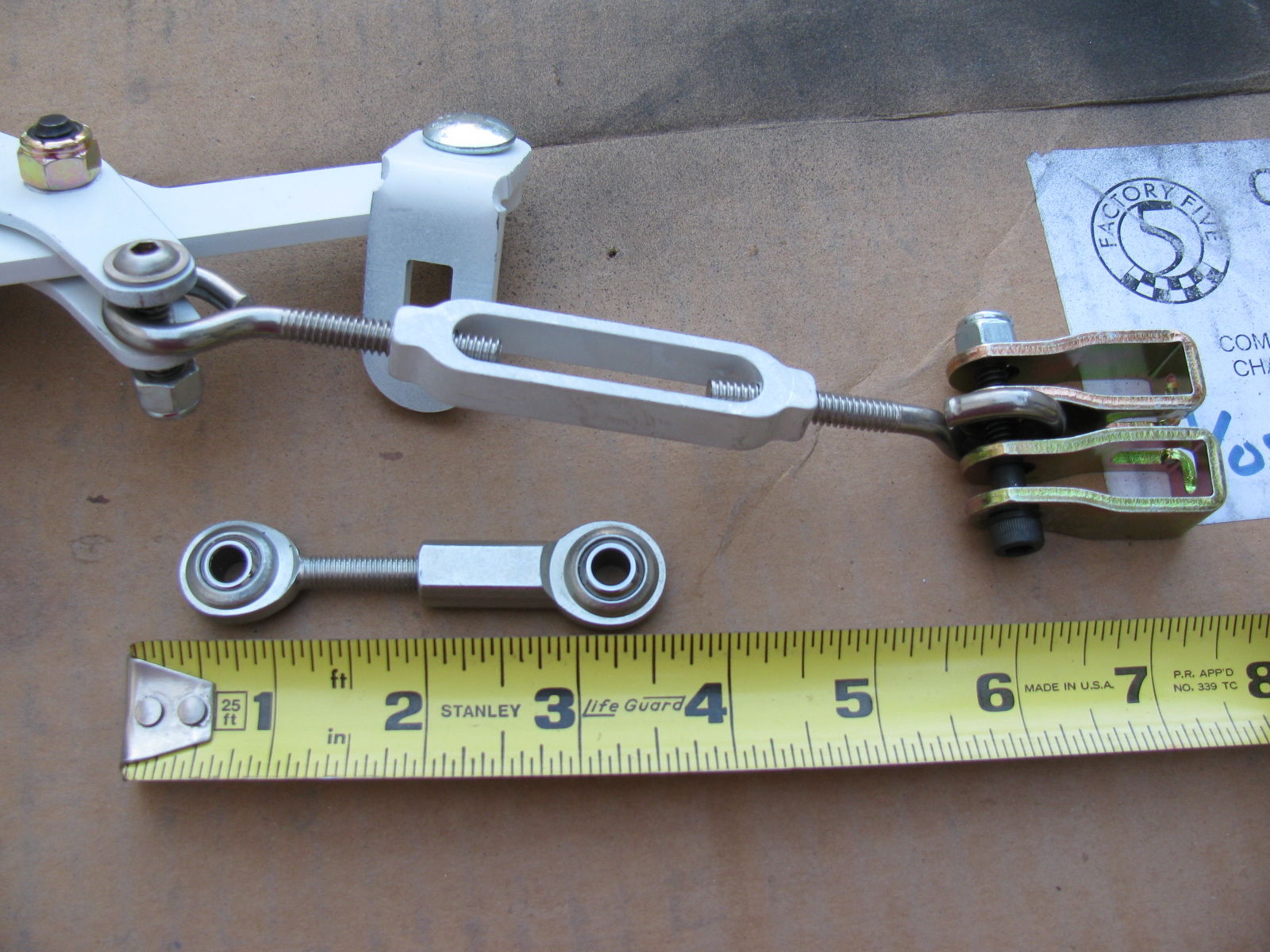
I may have a solution to this, based on some Forum postings on this same topic — see the photo below. I do not like the turn buckle from the hardware store, I think I should replace it with a stainless steel clevis six to eight inches long to allow for adjustment. (McMaster-Carr items. . . )
UPDATE: I ordered an e-brake kit from Richard Oben of North Race Cars. (The same place I ordered my air conditioner – yet to be installed). The kit will move the e-brake to a more practical location at the top of the transmission tunnel.
Many builders of the Roadster as well as the Coupe do not like the way the brake cables rub against the big four inch tube. I will make a small Teflon block and mount it to the bottom of the chassis so the cable can slide more easily, and make it look much nicer. More details when I get to that step.
Main Wire Harness
I started laying out the main wire harness. A few weeks ago, I painted the fuse panel with white appliance epoxy paint. This will brighten up the underside of the dash and will prevent corrosion. Based on something I read on the Roadster section of one of the F5R Forums, I added a small hinge to the fuse panel mounting plate. You can see the hinge on the right side of the bracket in this picture:

However, this is bad advice, at least for my Coupe application. This is not a good thing to do for several reasons:
1) It moves the fuse block about a quarter-inch forward into the footbox, and adds strain to several wires in the Ron Francis harness supplied with the Complete Kit.
2) The reason for the hinge was to make it possible to swing the entire panel down for easy servicing. However, this is impossible, since there is not enough slack and the thick harness will not allow the fuse panel to simply “swing down.”
3) The mounting holes must be very close to the edge of the 2-inch rail. Removing the hinge makes a better location for the mounting screws.
After removing the hinge, and mounting the fuse panel per the instructions, I noticed some “squishiness” in the fuse panel, which I do not like. I have not seen this mentioned in any post so I thought I would bring it up here.
The fuse panel is a piece of thin aluminum, laser cut to shape to hold the plastic fuse panel. Three zip screws (the self-tapping hex-head screws that held the cockpit aluminum in place when the kit was shipped) fasten it in place under the driver footbox, near the steering column.
All fine and dandy, but the fourth corner is “floating in space” and flexes easily. I decided to add a small aluminum bracket to make the fuse panel stronger (flex less). I hope the bracket does not get in the way of anything to be mounted later….

