Archive for the ‘automotive air conditioning’ Tag

Type 65 Coupe Project Update: Preparing for Engine Installation   1 comment

IMG_2614 IMG_2615

I spent the last two weekends in the garage, getting back to the Coupe Project. It was nice and relaxing to lay on the creeper, under the chassis and working with tools again.

I had to modify the chassis in the pedal box area to allow more clutch pedal movement. This is a known issue in the Roadster forums, but not so much in the Coupe forums. This happened when Factory Five Racing changed the Wilwood pedal box – the old version would actually break. The new and improved pedal box moves the clutch pedal arm over to the left by about an inch or so, and the arm hits a brace, limiting pedal travel.

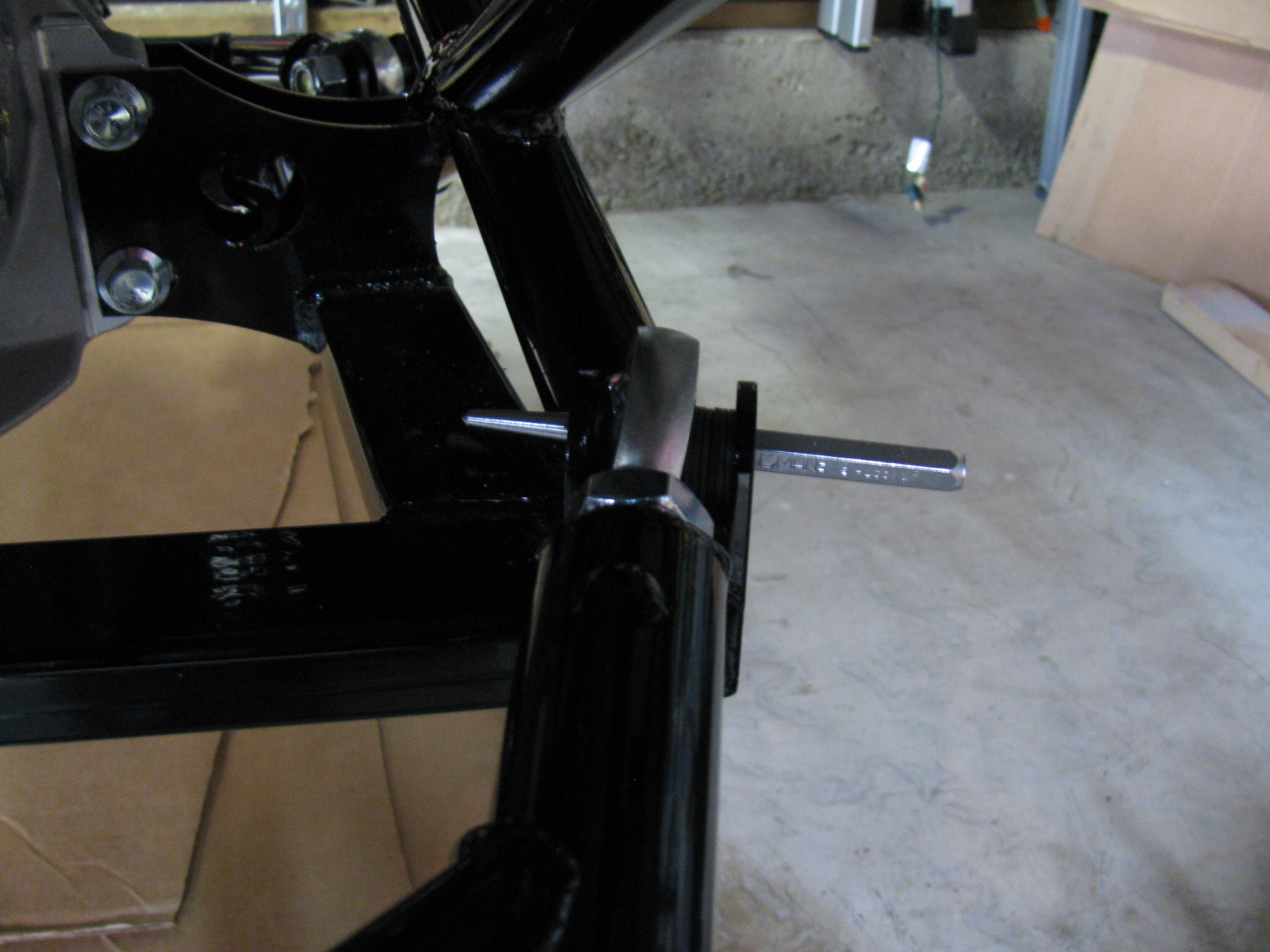
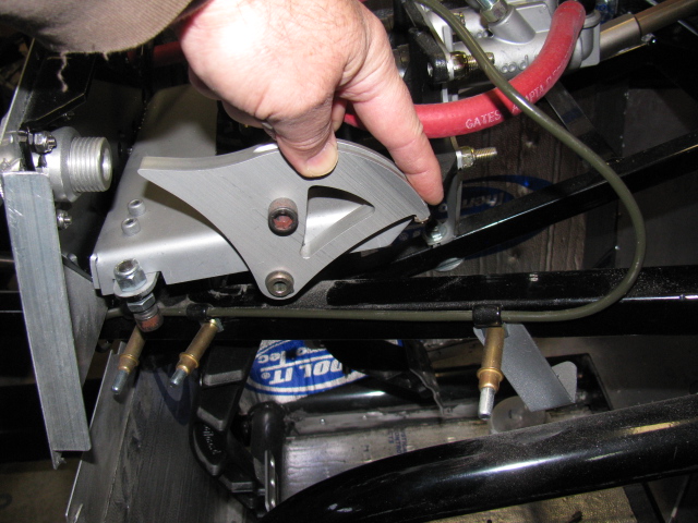
When the modification is done before the pedal box is bolted into place, it is a simple chore to make two cuts, chopping a small triangular cut into the frame member. This can be done with a reciprocating saw or maybe power jigsaw.

However, if the modification must be performed after the pedal box is bolted into place, the tube must be accessed from below, in an awkward angle. A small grinder tool would be ideal for this, but the only tool I have that will fit the space and the angle is a Dremel tool. It took me two half-day sessions to do this.

IMG_2626 IMG_2625

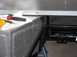
In the pictures above you can see the half-moon shape cutout I had to make. This is a view from under the chassis, looking up from the creeper. This will be painted black later. The tube looks normal from the top, so that is good. And clutch pedal travel is doubled, so free play adjustment range should be much better.

Since the brake system is installed, filled and bled, I removed the Clekos and riveted the lines in place. I changed several P-clip anchor points so it complies with my “routing and clipping manual” from the office. Unfortunately, I followed some other builders’ clipping, and mounted several p-clips upside down. Most of them will be under the car, and might be hidden from view when the car is finished. But I know they are upside down.

Here is a picture of how the clips should be mounted. This is the X-member in the front of the chassis.

IMG_2624

Looks like I didn’t take a picture of the riveted clips. I will post them later.

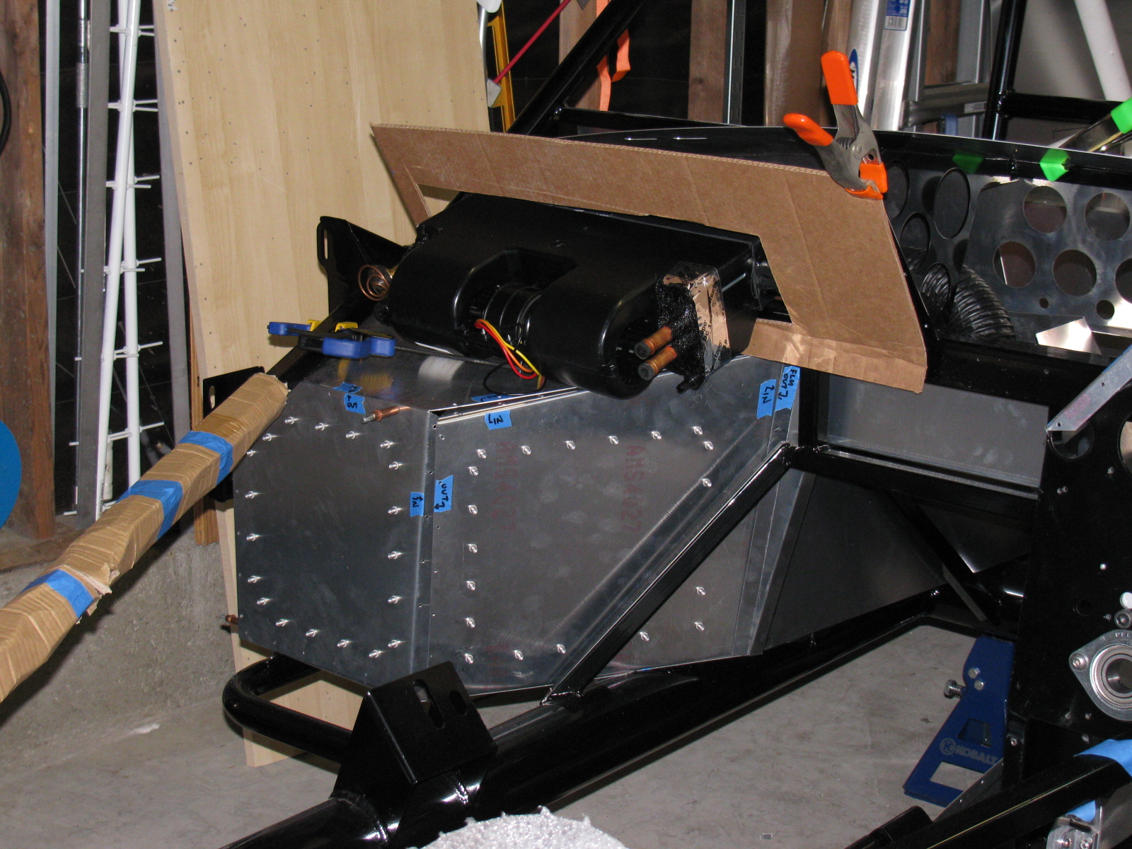
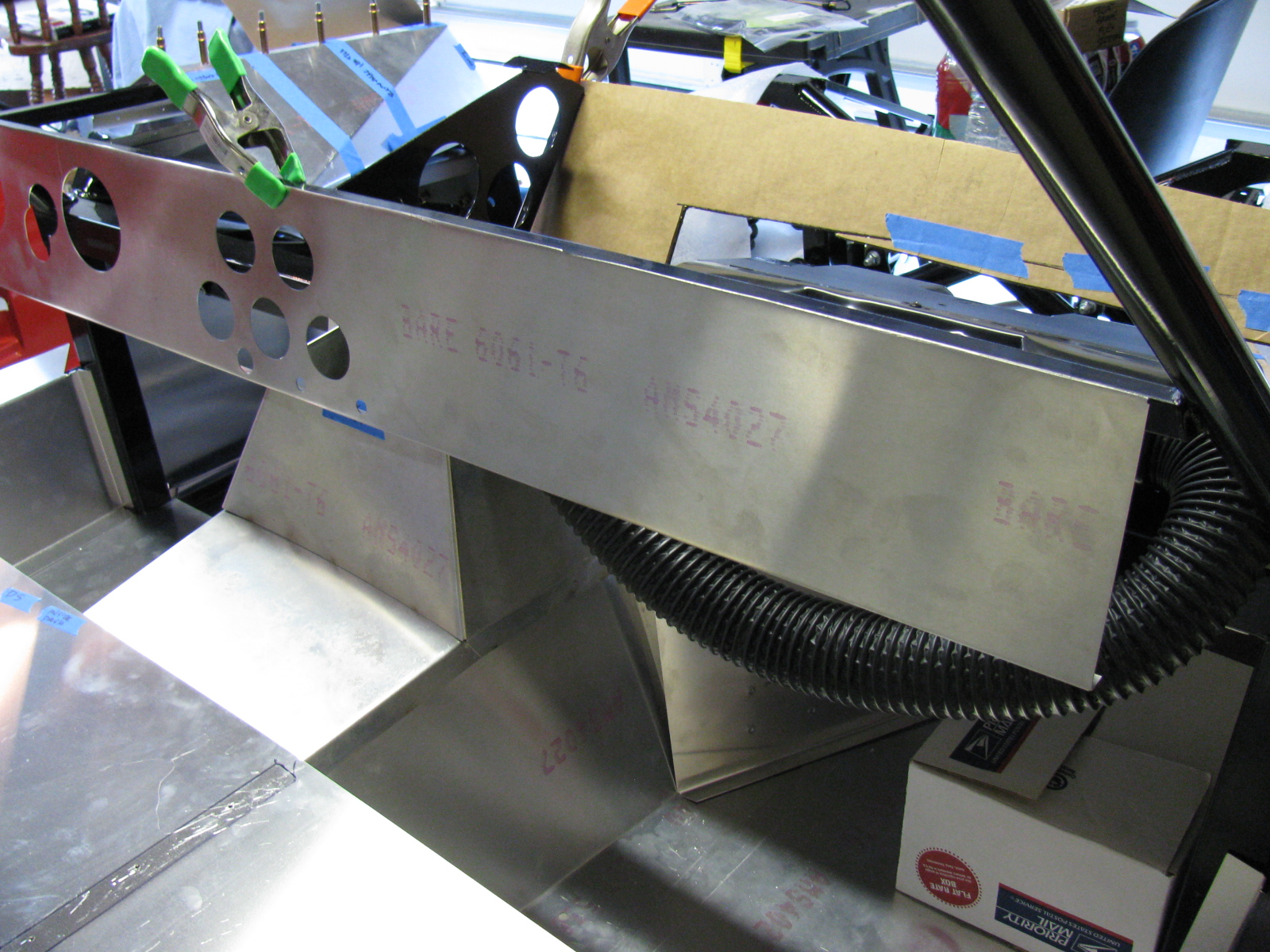
Next, I made a bracket to support the ECU for the MSD Atomic fuel injection system for my 302. This plate will secure the ECU and provide strain relief for the cables going in and out of the unit. It is on a plate so it can be easily removed if I have to work on the wiring or the ECU later. It is mounted with 1/4-20 stainless steel studs and nylon lock washers. It was raining so I was not able to paint this plate. Will have to do that at the next build session.

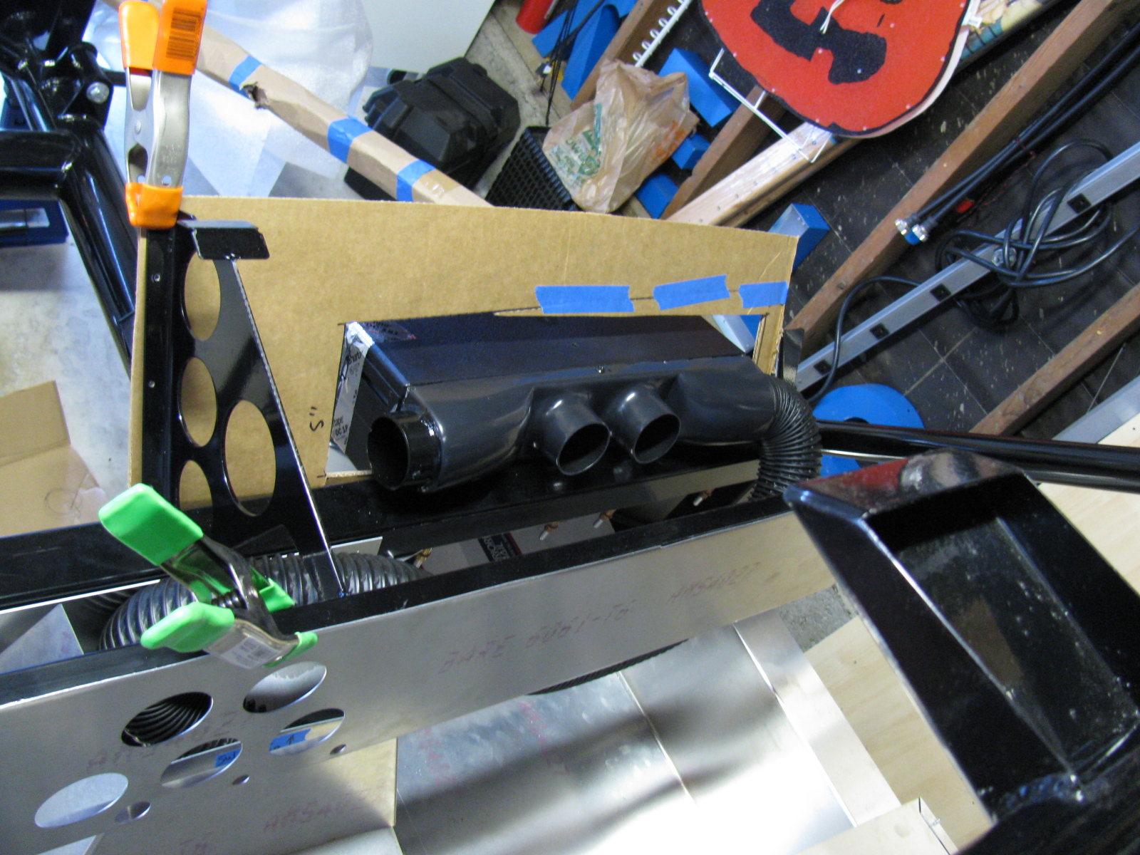
The passenger side footbox is on the left. Three stainless steel Allen head screws come through the wall and into the passenger box. The center photo shown the ECU engine cable going into the engine bay, and the right photo shows the MSD computer and plate inside the passenger footbox. Carpet will cover the interior, so a carpeted cover will be made to hide the ECU and wires when the car is finished.

I am also laying out the air conditioner system components on the chassis. I have to make several brackets and small boxes to mount the A/C components on the chassis.

As I was doing this work, I took another look at the battery box mentioned in an earlier post. It is installed with clecos so it can be removed. I think I want to mount the battery above the passenger footbox. Two reasons for this:

First, it will shorten the battery cables, decreasing the voltage drop.

Second, the “factory location” for the battery – in the rear center – blocks the rear axle pumpkin. So, when I have to change the oil or make adjustments, the battery must be disconnected and the battery and the box must be removed. Sounds like a painful procedure for a simple maintenance chore.

I will make a mock-up of this in my next build session. Stay tuned . . . .


Type 65 Coupe Update: E-Brake Handle, Fitting the A/C and More IRS – and Maker Faire 2013 Application   Leave a comment

I got tired of fiddling with the IRS so I did something different this weekend. Here is a picture of the E-brake ratchet handle that comes with the Complete Kit. Since the parts are plain, un-finished steel, I decided to paint it to prevent rust. The exploded view in the instructions make assembly very easy. I wish The Factory would include an exploded view for the IFS as well as the IRS – makes things go so much better. The finish is white and black appliance epoxy from Rustoleum.

Here are some pictures. . .

kh6wz-3-10-13 002

kh6wz-3-10-13 001

I am not sure if I like the location of the E-brake handle, it is on the passenger side of the transmission hump. A popular modification is to use a Pontiac Fiero unit and re-locate it closer to the driver. We’ll see if I want to change this setup. (The sharp-eyed people will notice the e-brake handle is backwards. . . . . . )

Here are some images of the air conditioner and a cardboard aided design (CAD) templates I am making. This requires some cutting of the dashboard and firewall, so I want to mock everything up before I start cutting. I have some very sturdy aluminium plates for the A/C baseplate, and some sheet aluminum for the enclosure. A CAD version will be made first, then transferred to aluminum.

kh6wz-3-10-13 015

kh6wz-3-10-13 013

kh6wz-3-10-13 012

kh6wz-3-10-13 009

kh6wz-3-10-13 010

kh6wz-3-10-13 009

Moving back to the IRS, I received some advice from the veteran builders, and so here is what I did to the lower control arm mounts. The shims (thin black steel washers) F5R supplies are slipped into place and some adjustment is done by placing shims here and there. However, it makes more sense to limit the toe and camber adjusters so that the tweaking can be as simple as possible. By “fixing” one side of the control arm, and limiting it to one adjuster for toe and one adjuster for camber, alignment is simplified and less time consuming.

Currently, this stage is to just “eyeball” the adjustments, and continue the build process. Wheel alignments – both front and rear – may be done after the wheels and tires are mounted. (Probably can be done at the “go kart” stage, when the chassis is complete and the engine, drivetrain, electrics and brakes are installed and running.)

Here are some pictures. As this step gets closer to completion, I will add more details for future reference.

kh6wz-3-10-13 007

kh6wz-3-10-13 004

Above left: The Type 65 Coupe IRS lower control arm mounts. One shim on the front side of the mount, six shims on the side toward the rear of the car. The heim joint is threaded on so that 5/8-ths of an inch of thread are showing.

Above right: Here is the trick I use to install slippery washers, shims and spacers onto things – Use a punch or some other tool to poke through the stack of parts together, thus aligning the holes of each part. Then . . .

kh6wz-3-10-13 005

kh6wz-3-10-13 006

. . . push the fastener – and the punch – through the stack of parts. Wiggling, pushing and pulling will help. Sometimes a quick-clamp can help, too.

Maker Faire 2013 Update: Application is In!

I turned in an application for Maker Faire Bay Area 2013. Our Maker name is “Not Your Grandpa’s Ham Radio 2” and we will continue the theme my team entered last year. We will have some new projects on display, and we will bring some of the more popular items from last year. Here is a look at some of our projects from last year – as well as some other interesting and amazing things I saw last year.

Maker Faire 2012-1 027

Maker Faire 2012-1 036

Maker Faire 2012-1 049

Maker Faire 2012-2 010

Maker Faire 2012-1 076

Maker Faire 2012-1 073

Maker Faire 2012-1 072

Above – One of the most interesting exhibits at Maker Faire 2012 — The Electric Giraffe named Russell  – it is a scaled-up and enhanced version of a plastic model kit – it is 17 feet tall. Below left: Jeri Ellsworth, aka Circuit Girl, and her electric Key-Tar at Maker Faire 2012. Below right, Maker Alex shows us her finger tip no keyboard keyboard.

Maker Faire 2012-2 120

Maker Faire 2012-2 066


More Maker Faire 2012 images are posted on my YouTube channel.