Since the engine is in the middle of my garage, I really need to accelerate my building, or at least, get my chassis ready for engine installation.
I looked at my cookie sheet heat shields and the mounting locations filled with 8-32 riv-nuts, and thought – shoot, the riv-nuts actually have a shaft that might be used as stand-offs for the shield plates. So I checked the length, and the threaded shafts are about a quarter-inch long, enough to be used as a spacer between the firewall and the heat shield. I may add another quarter-inch in certain places, if there is room.
So I spent a few hours removing all of the riv-nuts I installed a few weeks ago. Good thing I bought several hundred from McMaster-Carr. . . .
At least I am an expert on installing and extracting riv-nuts now.
Rivet Nuts and the Rivet Nut Tool
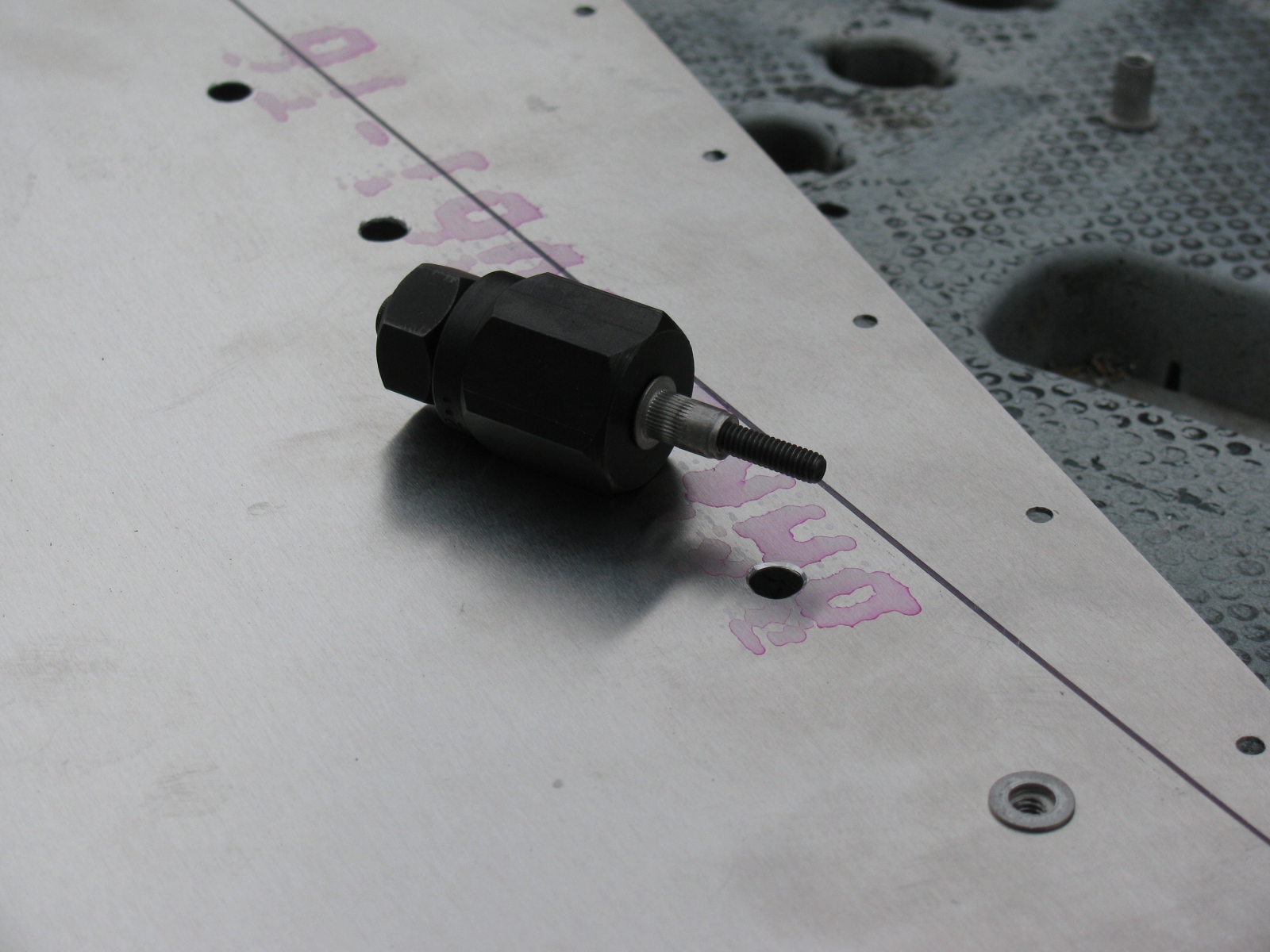
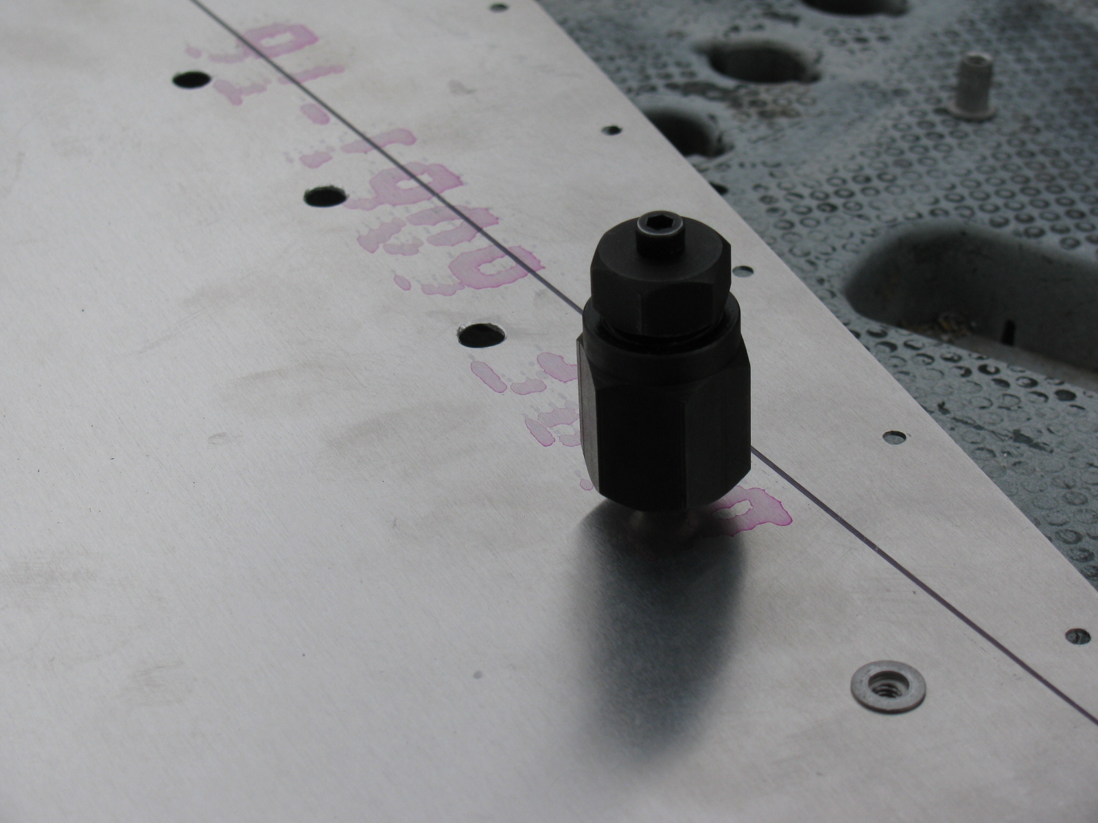
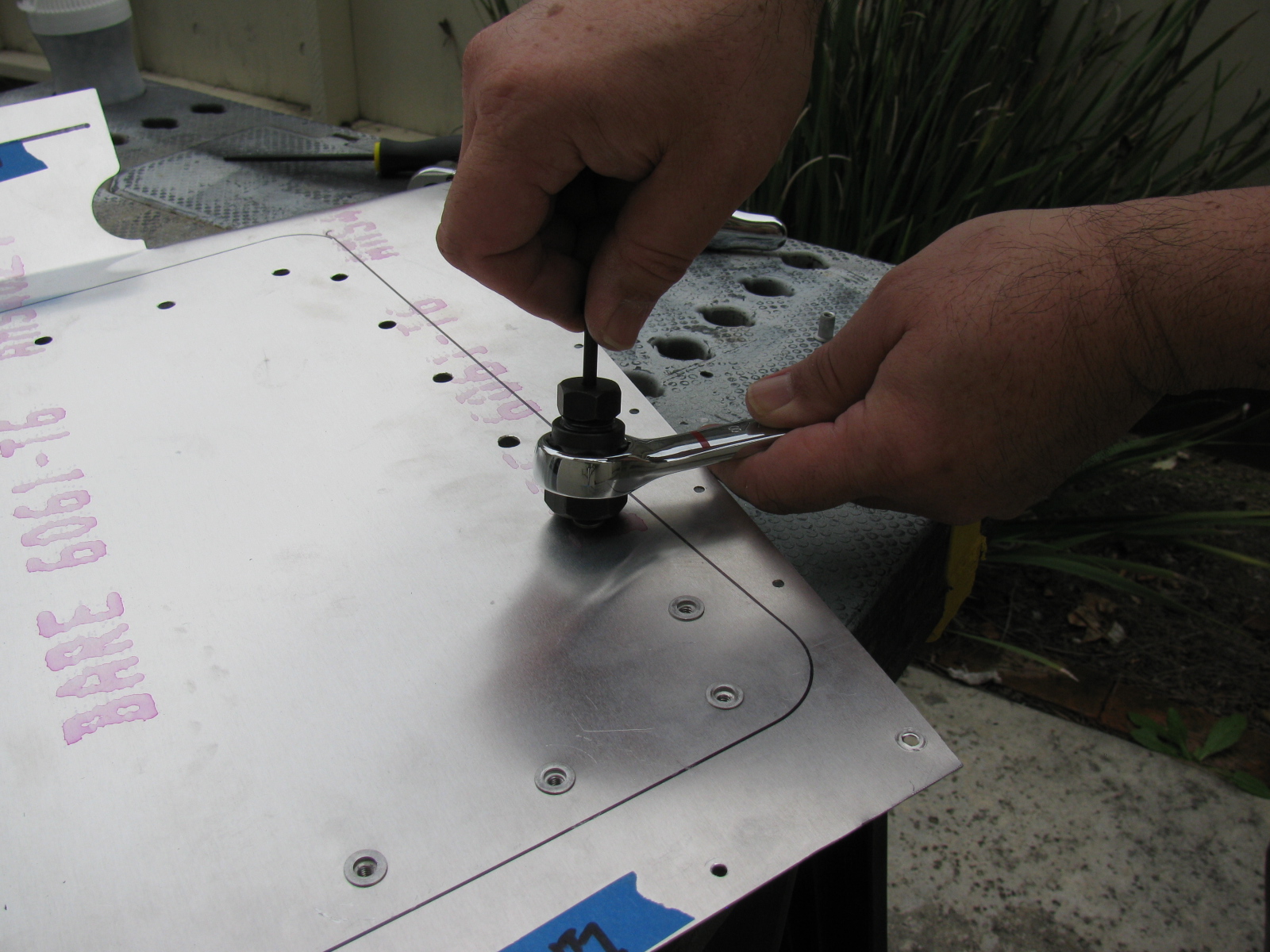
Here are some pictures of the riv-nut tool from McMaster-Carr and how it is used. Riv-nut fasteners are very handy if you need a threaded hole installed into a blind location, or when you do not have access to the back side of a mounting surface. I will use these fasteners for hatches and compartments in the trunk area of the Type 65 Coupe.
McMaster-Carr information
Wrench-drive rivet nut installation tool for 10-24 and 10-32 thread: 96349A203
Wrench-drive rivet nut installation tool for 8-32 thread: 96349A152
Wrench-drive rivet nut installation tool for 6-32 thread: 96349A101
Aluminum heavy-duty rivet nut, 6-32 internal thread, .080″-.130″ material thickness, packs of 25: 94020A315
Aluminum heavy-duty rivet nut, 8-32 internal thread, .080″-.130″ material thickness, packs of 25: 94020A323
Aluminum heavy-duty rivet nut, 8-32 internal thread, .020″-.080″ material thickness, packs of 25: 94020A319

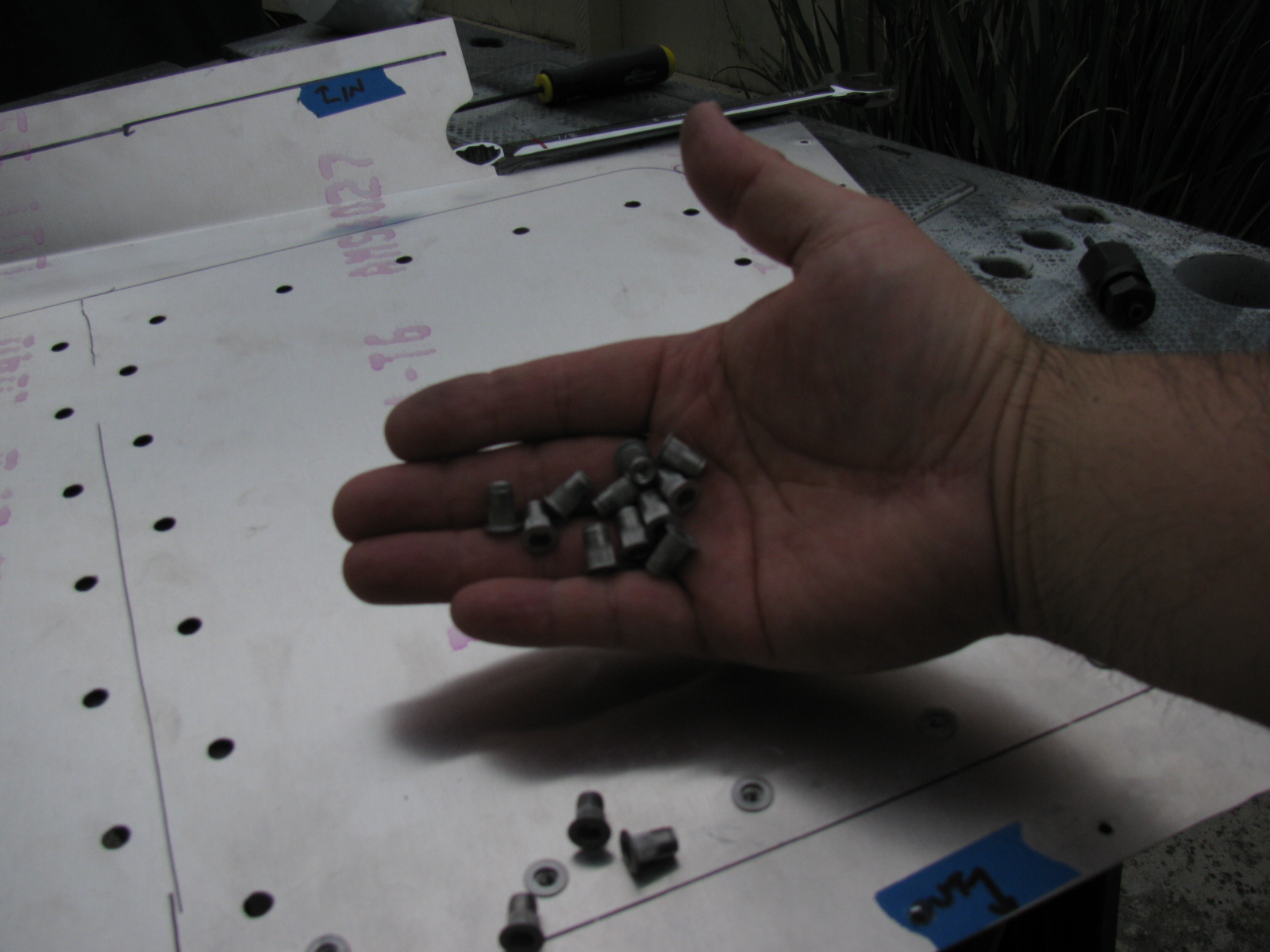

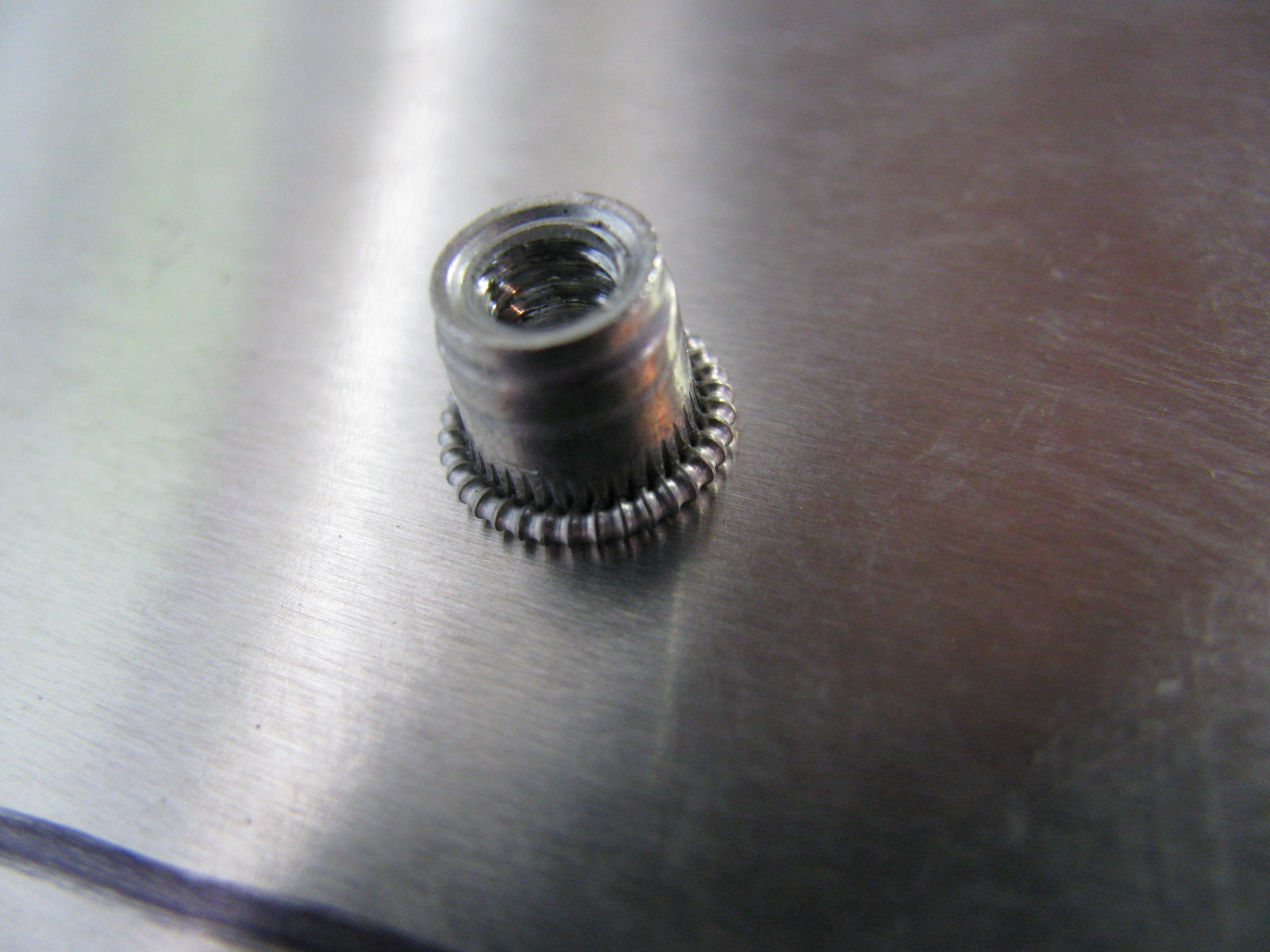

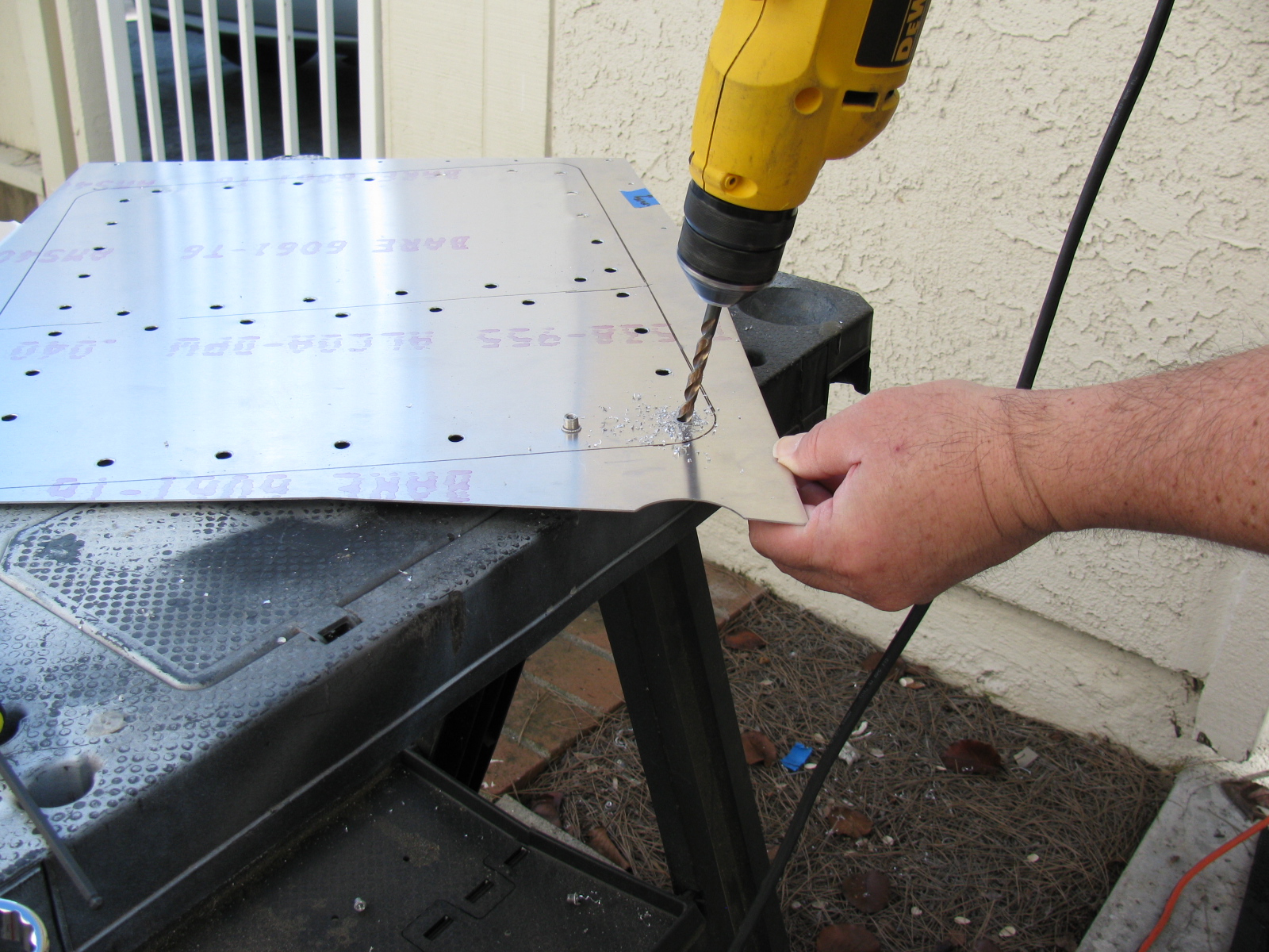
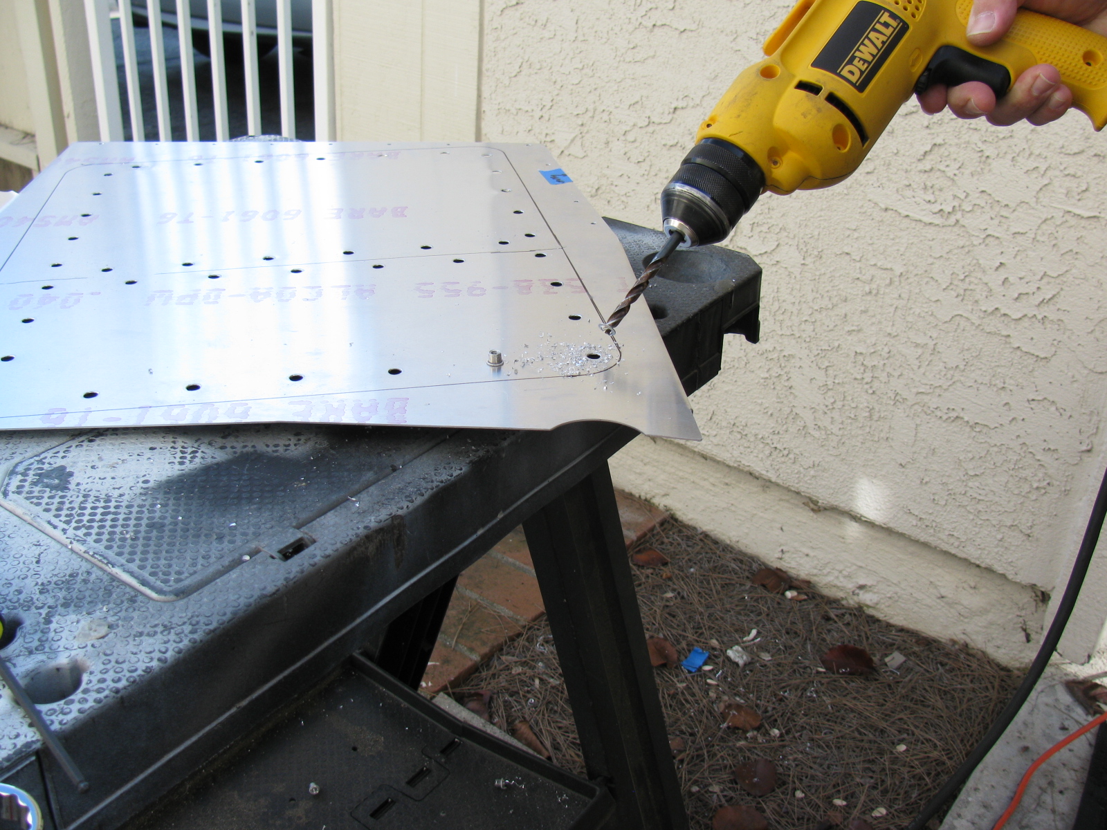
Above left – a picture of a properly installed riv-nut, viewed from the reverse (back) side. At right, a riv-nut improperly installed, viewed from the face (front) side. This one must be removed by drilling the riv-nut out. Below left, use a twist drill slightly smaller than the mounting hole, in this case, a 1/4-inch bit is being used to drill out the riv-nut. By slightly rocking the drill, the riv-nut will break apart and, usually, just fall out of its hole.
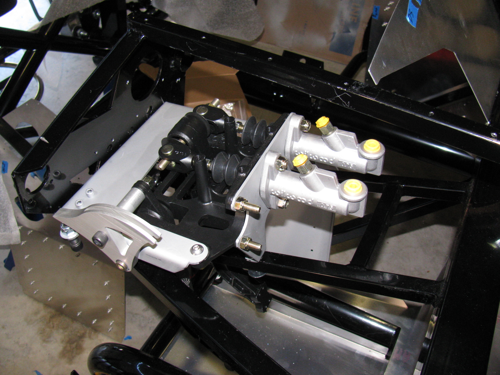
Give Me a Brake: The Wilwood Pedal Box
The pedal box is a challenge to install with the Factory Five Racing Assembly Manual, revision 3E, July 2011 – since there are no assembly instructions for the Wilwood Complete Kit pedal box.
Fortunately, a dedicated Type 65 Coupe builder named Chris has an excellent photo album of his Coupe build, with many detailed images. Without his documentation – it would have been impossible to assemble this part of the kit. Take a look at cbergquist1’s photostream on Flickr.
Here are some pictures of my pedal box, including a trouble spot I ran into, and how I had to fix it. . . .

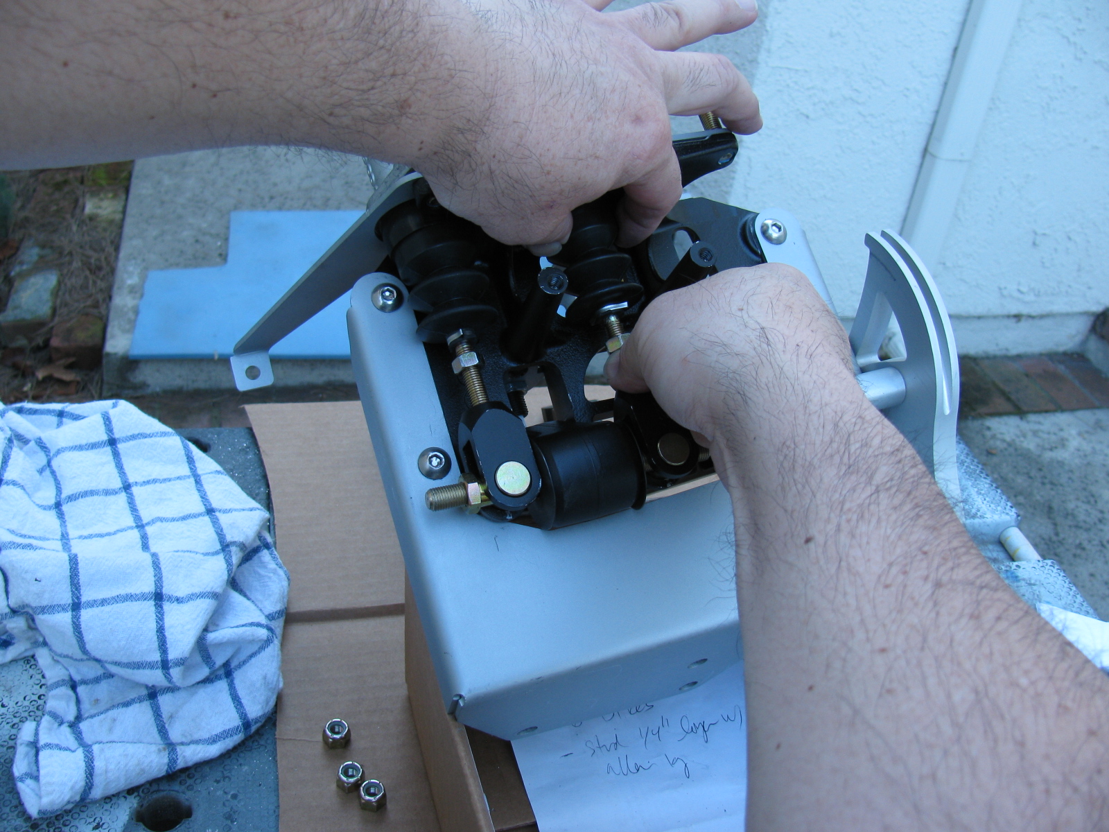
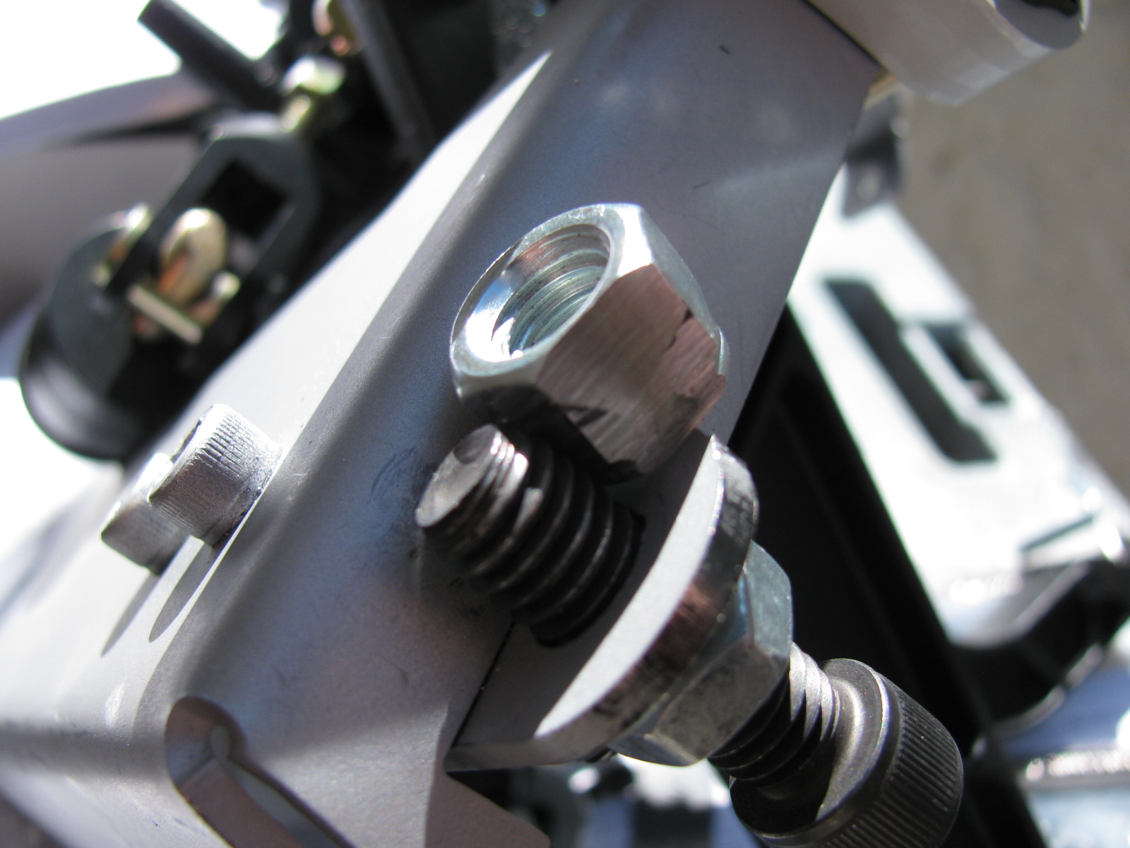
This is the clutch quadrant adjuster (above). This Nylok had to be ground down to fit properly. The hole in the adjuster plate is too close to the master cylinder mounting plate. A better solution would be to eliminate the Nylok altogether and thread the small plate. Then the lock nut and Allen bolt are used to make clutch travel adjustments.

Now I have to find a place to mount the master cylinder reservoir. There are some rare posts about this, but most of them are for the Factory Five Racing Roadster.
I think I will mount mine at or near the peak of the driver’s side footbox/firewall. This location should be away from too much heat, and should be in the clear for fluid bleeding, checks and re-filling. We will see. . .
The Gas Pedal

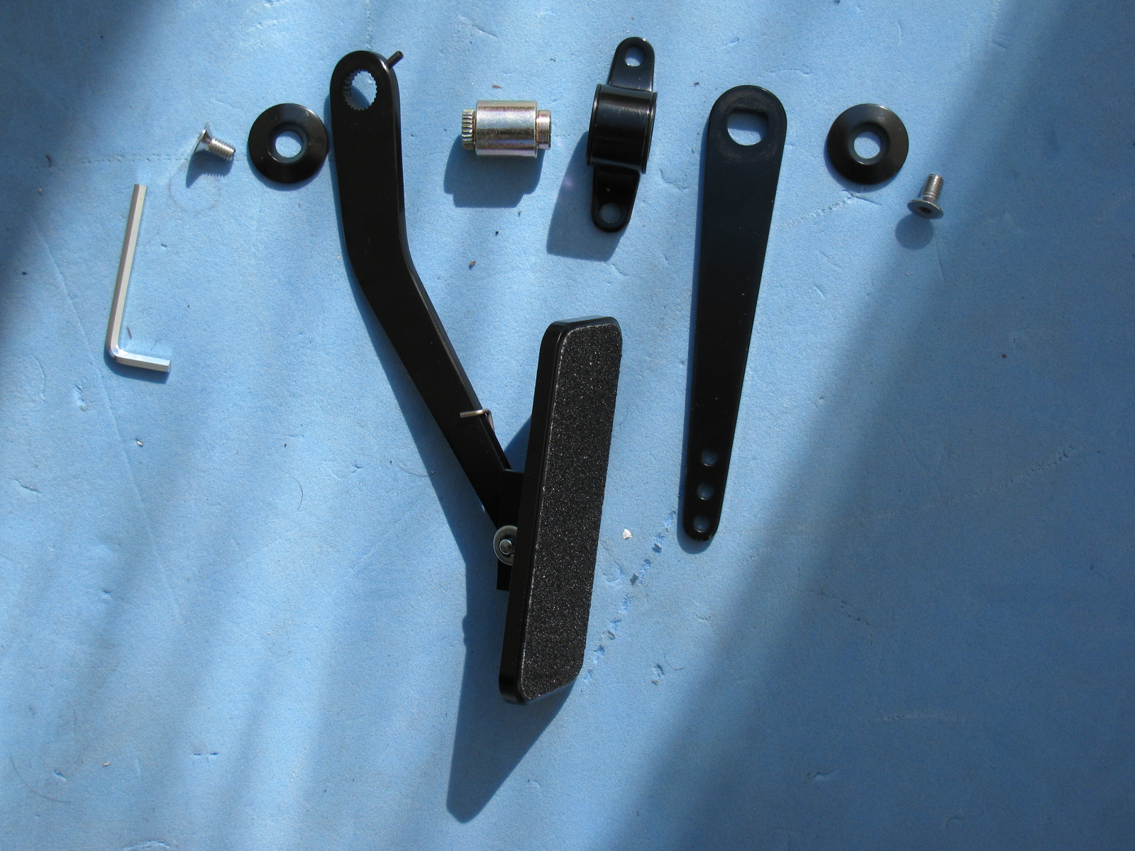
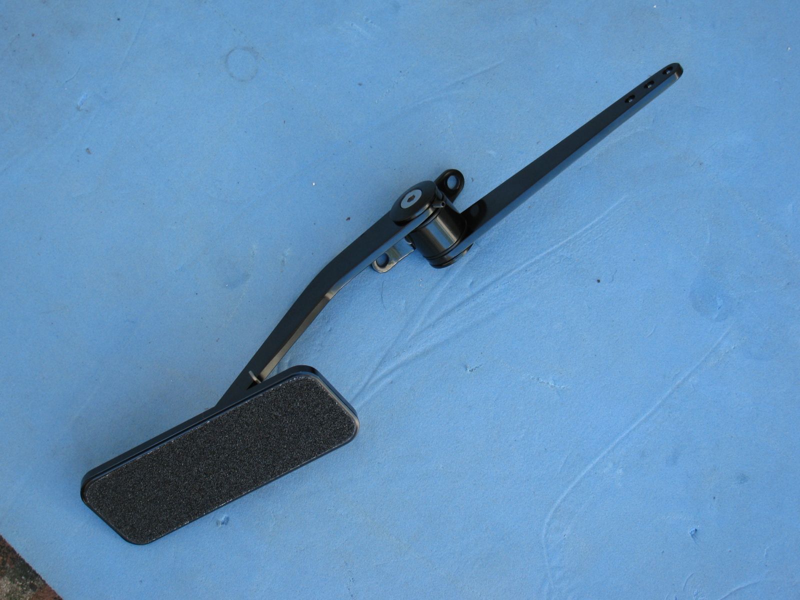


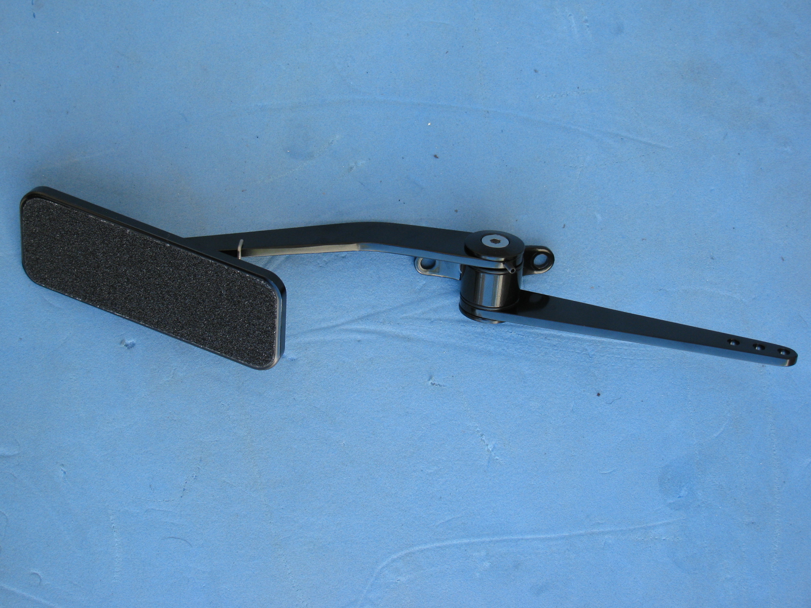
Part of the pedal box area is the accelerator pedal. Again, instructions are very skimpy on how to put this thing together. Here are some pictures of the gas pedal parts and how to dis-assemble the unit as it comes out of the box, and where it mounts onto the firewall area. Adjustments for the pedal box and accelerator pedal will happen later.

I am regular reader, how are you everybody? This post
posted at this site is actually good.