Archive for the ‘clutch’ Tag


I spent the last two weekends in the garage, getting back to the Coupe Project. It was nice and relaxing to lay on the creeper, under the chassis and working with tools again.
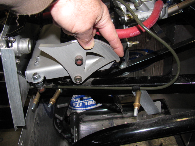
I had to modify the chassis in the pedal box area to allow more clutch pedal movement. This is a known issue in the Roadster forums, but not so much in the Coupe forums. This happened when Factory Five Racing changed the Wilwood pedal box – the old version would actually break. The new and improved pedal box moves the clutch pedal arm over to the left by about an inch or so, and the arm hits a brace, limiting pedal travel.
When the modification is done before the pedal box is bolted into place, it is a simple chore to make two cuts, chopping a small triangular cut into the frame member. This can be done with a reciprocating saw or maybe power jigsaw.
However, if the modification must be performed after the pedal box is bolted into place, the tube must be accessed from below, in an awkward angle. A small grinder tool would be ideal for this, but the only tool I have that will fit the space and the angle is a Dremel tool. It took me two half-day sessions to do this.


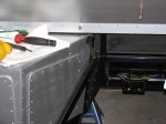
In the pictures above you can see the half-moon shape cutout I had to make. This is a view from under the chassis, looking up from the creeper. This will be painted black later. The tube looks normal from the top, so that is good. And clutch pedal travel is doubled, so free play adjustment range should be much better.
Since the brake system is installed, filled and bled, I removed the Clekos and riveted the lines in place. I changed several P-clip anchor points so it complies with my “routing and clipping manual” from the office. Unfortunately, I followed some other builders’ clipping, and mounted several p-clips upside down. Most of them will be under the car, and might be hidden from view when the car is finished. But I know they are upside down.
Here is a picture of how the clips should be mounted. This is the X-member in the front of the chassis.

Looks like I didn’t take a picture of the riveted clips. I will post them later.
Next, I made a bracket to support the ECU for the MSD Atomic fuel injection system for my 302. This plate will secure the ECU and provide strain relief for the cables going in and out of the unit. It is on a plate so it can be easily removed if I have to work on the wiring or the ECU later. It is mounted with 1/4-20 stainless steel studs and nylon lock washers. It was raining so I was not able to paint this plate. Will have to do that at the next build session.
The passenger side footbox is on the left. Three stainless steel Allen head screws come through the wall and into the passenger box. The center photo shown the ECU engine cable going into the engine bay, and the right photo shows the MSD computer and plate inside the passenger footbox. Carpet will cover the interior, so a carpeted cover will be made to hide the ECU and wires when the car is finished.
I am also laying out the air conditioner system components on the chassis. I have to make several brackets and small boxes to mount the A/C components on the chassis.
As I was doing this work, I took another look at the battery box mentioned in an earlier post. It is installed with clecos so it can be removed. I think I want to mount the battery above the passenger footbox. Two reasons for this:
First, it will shorten the battery cables, decreasing the voltage drop.
Second, the “factory location” for the battery – in the rear center – blocks the rear axle pumpkin. So, when I have to change the oil or make adjustments, the battery must be disconnected and the battery and the box must be removed. Sounds like a painful procedure for a simple maintenance chore.
I will make a mock-up of this in my next build session. Stay tuned . . . .
The San Bernardino Microwave Society (SBMS) had a Christmas party this past weekend, and it was a good break from doing sheet aluminum work. The event seemed smaller this year, several of the usual suspects were not able to make it. There was lots of food to share and gifts to exchange. Happily, regular guests Mel WA6JBD and his better half, Tisza KI6DBR came and brought their usual homemade treats, including Tisza’s famous chocolate truffles, microwave dish cookies and a chocolate sculpture. This year’s sculpture was a 10GHz horn and a section of waveguide. And yes, they really do work at 10GHz. Mel measured the return loss of the horn and waveguide and reports more than 17dB or something like that – pretty respectable for an edible 10GHz antenna.
Here are some pictures of the event. . .

Where else but a ham radio Christmas party would one find a 10GHz horn and waveguide made of chocolate – that actually works

Tisza’s homemade chocolate truffles – Yum!


Gift exchange crowd
What in the World is That?
After the party wound down, I stayed to get a closer look at Dennis’ new camera. It does not look anything like a camera, but it really shouldn’t because it makes images in a whole new way and enables a whole new way to enjoy still images. I thought it looked more like a kid’s kaleidoscope, rather than a camera.
The camera and lens system optics look very simple. And that is one of the points: You do not need fancy telephoto or macro lens capability. It is done in software. There are no fancy controls or buttons, only soft pads on the rubberized parts of the case. There is a power switch, a zoom control and a shutter release. An LCD with touch screen is on the back. Here are some pictures of this new gadget.

WHAT is THAT!

The Lytro camera. At left is the lens cover, it attaches magnetically. That’s an item that will be lost immediately. Center, the camera, showing the front glass and lens. Right – a tripod adaptor.
As I mentioned on my LinkedIn update, the Lytro camera introduces a paradigm shift in the way we can look at still pictures (pun intended, sorry). At first, I thought this camera simply used some sort of image processing to “fix” images, simple things like contrast and color adjustments and maybe some image manipulation, like PhotoShop. But then Dennis said that you can change focus and “raw image” features, like zooming in – after the image is stored on your computer.
The images are not jpg or other familiar formats – but then – these are not ordinary images, either. You can actually change the depth-of-field – change the point of view of the image.
Watching some of the demos on the Lytros website made me think of scenes from the TV show “CSI:” because you can see an image captured by the camera, and you can actually zoom and move around the various places on the image, and see what else the camera captured.
Visit the Lytro website, pictures and demos and details are worth closer examination. Unfortunately, I don’t have any Lytro images to share – yet.
The Coupe Goof
The day after the party, I went back to work on the Coupe. Something bothered me as I looked at the images and some postings of other builders. The driver’s side footbox and the front, where the pedal box mounts, looked different than mine. And I found another driver side footbox front panel in my box of aluminum parts. I looked at the part number of the “extra” footbox front (15312) on the packing slip, and noticed the description: “Driver Footbox Front Wall, Coupe Wilwood Pedals.”
Argh. Since I have the Complete Kit, it came with a Wilwood pedal box. Part of the confusion is the way Factory Five Racing packed the sheet aluminum – the major parts are held in place on the chassis and are shipped in place. This would be fine for the builders using a donor Mustang pedal box, the “Basic Kit” version.
So, I had to remove the driver side footbox front panel and replace it with the proper one. The good news is that I had all these things in place with Cleco fasteners, not rivets and silicone. And, I used the old panel as a drilling guide for the new panel. Now I have a spare sheet of aluminum I can use for – something. Hatch covers, maybe.

On the left is the wrong driver side footbox front panel. This is the one that is shipped in place on the chassis. The one on the right is the front panel for the Wilwood pedal box. Good thing I didn’t silicone and rivet that panel!

Disaster averted – the wrong footbox front panel was removed and replaced with the correct front panel for the Wilwood pedal box.