Archive for the ‘Uncategorized’ Category
I did not do much work in the garage this past weekend, since I had to pull an all-nighter to get my CQ magazine article finished before a deadline, and there was a Coupe welcome party at a fellow Factory Five builder’s house.
Here are some pictures of a brand new Type 65 Coupe kit that recently arrived at QSL and Mrs QSL’s house. (They just finished a Factory Five Racing Roadster. It looks great and is finally registered and running.)
It was good to meet some of the other builders in the area and see the special parts QSL bought for MRS QSL’s Coupe.
Follow the Casey Family Coupe Thread for the latest updates on Mike and Julie’s Type 65 Coupe.


I took a nap shortly after I got home, lack of sleep from the all-night writing session before wore me out. I woke up, and it was dark outside, so I just went back to sleep, and woke up at 3AM on Sunday.
After doing some chores around the house, I decided to prep and paint the other steel parts on the Coupe. Here are some before and after pictures of the steel items painted with gloss black Rust-Oleum Appliance Epoxy. It is a great finish, and looks almost like black powder coat.


For some reason I didn’t take a picture of the hatch hinge parts or the door frame after painting. Oh well.
Hopefully will be able to get some more work done on the chassis and the rear suspension in particular next time.
Stay tuned for more. . . .
Some Body Parts, More IRS Conundrum and a New Microwave Antenna for KH6WZ
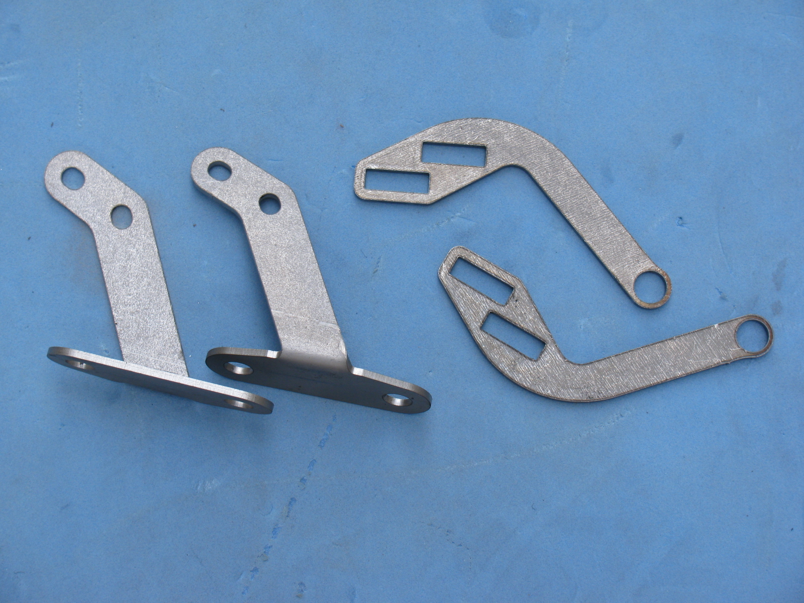
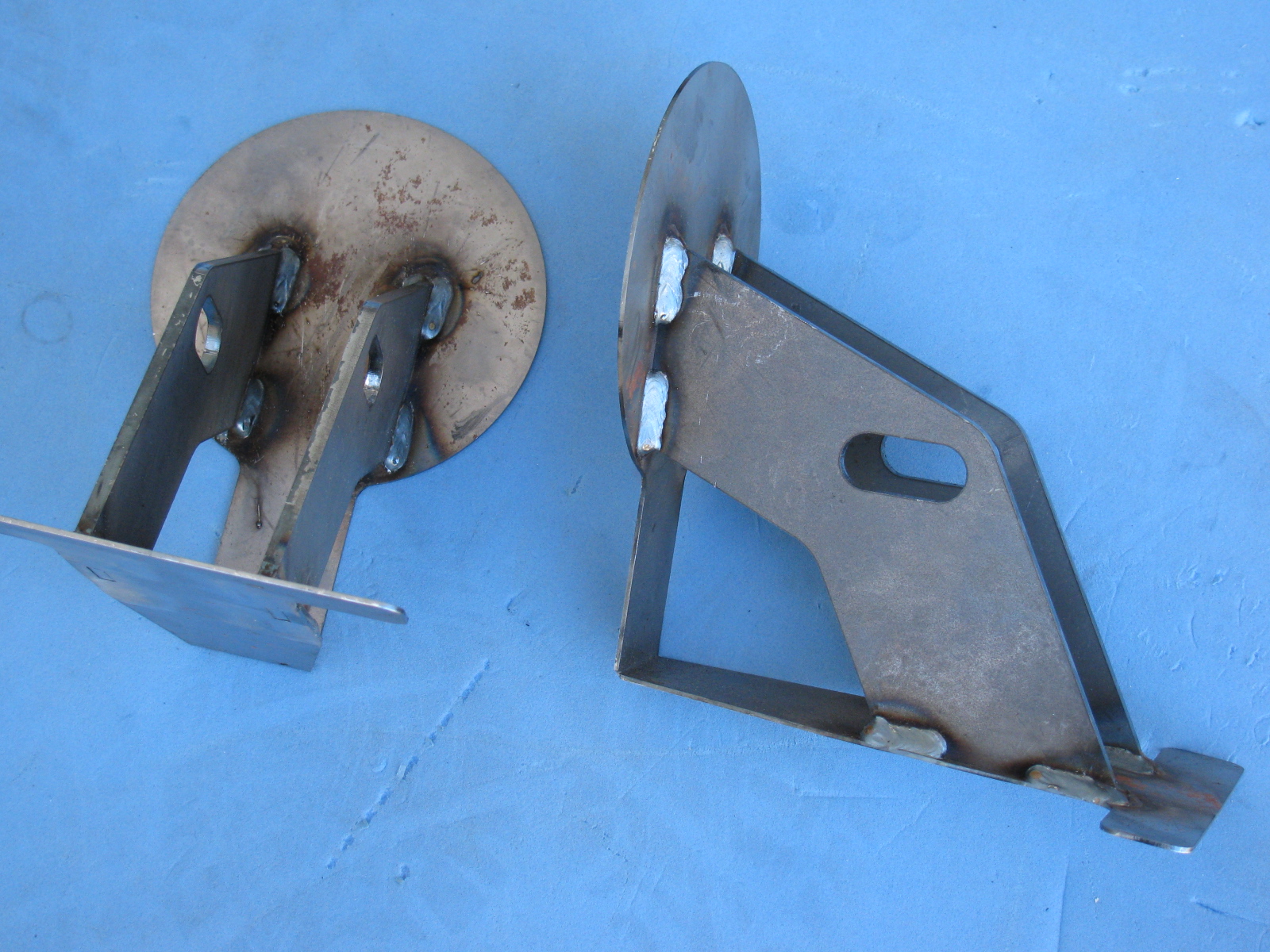
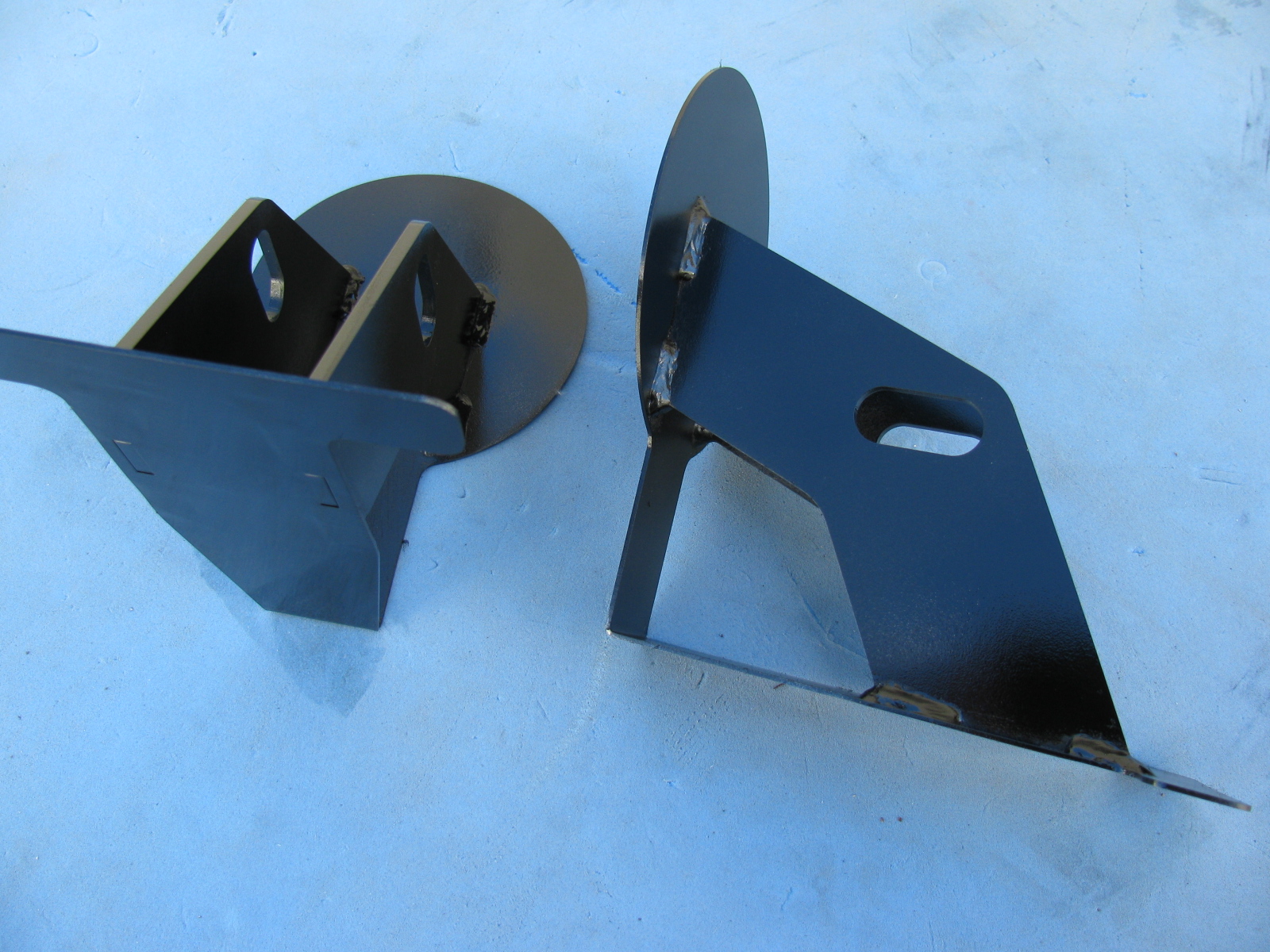
Inspired by a post on the Factory Five Racing forum and the dry and sunny weather this weekend, I decided to paint some of my body mounting parts. I am using gloss black Rust-Oleum Appliance Epoxy paint for these pieces. I have used this paint for my electronic and radio projects with good results. The paint dries very hard and is waterproof and washable, perfect for these parts.
Surface prep is easy for this paint, I scuff the surface with a 60 grit sanding disc on my random orbit sander. For the hard to reach nooks and crannies, I use a wire wheel chucked in my hand drill. Then I use liquid dish soap and water to wash off the grit and any oils. No primer is needed for this paint. Then I apply two or three light fog coats first, and then blast a thick coat for the fourth or fifth and final coat.
Here is a “before” and “after” picture of the front nose mounting hinge.

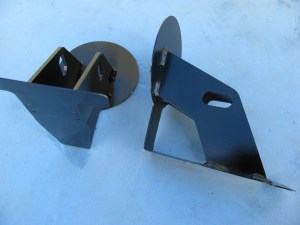
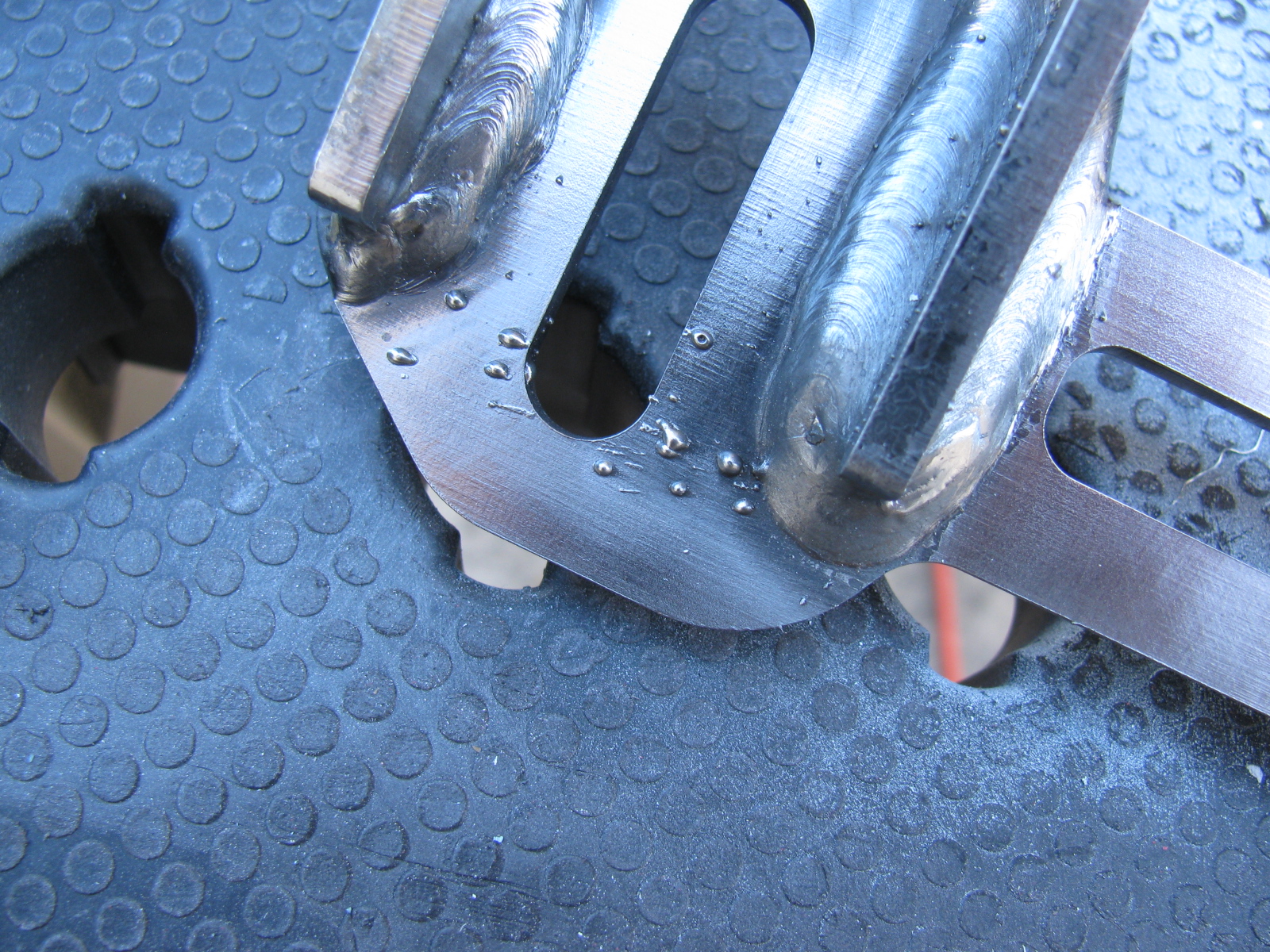
I did the same with the door hinges. Here you can see some weld splatter that will interfere with the mounting bolts, so I used a Dremel tool to grind those weld balls off.

Although many of these parts will not be seen, I do not want them to rust. Other parts will be painted in the same way, and include the door frames, the rear glass hatch hardware and the emergency brake mechanism.
Meanwhile . . .
After spending some time fiddling with the factory-supplied accelerator pedal, I decided to buy an aftermarket gas pedal instead. I ordered one of Russ Thompson’s gas pedals earlier this week from Breeze Automotive, one of the Factory Five Racing Forum supporters. I was amazed the box arrived on Thursday – that was fast!
The new gas pedal is really a machined aluminum sculpture. Pictures on this will be coming later, since I need to get the engine mounted before the gas pedal goes in.
IRS – Finished – Sort Of . . .
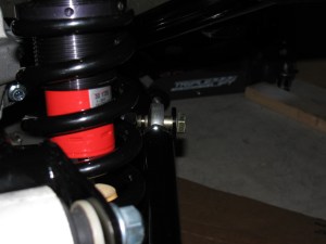
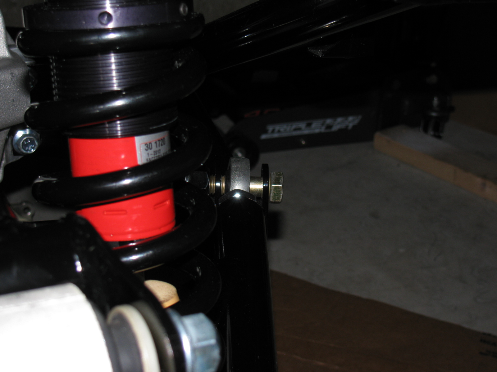
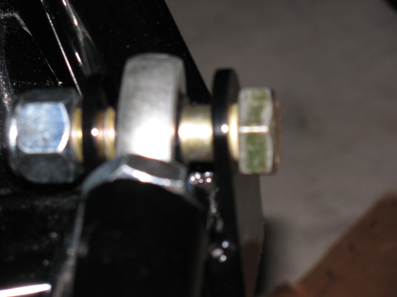
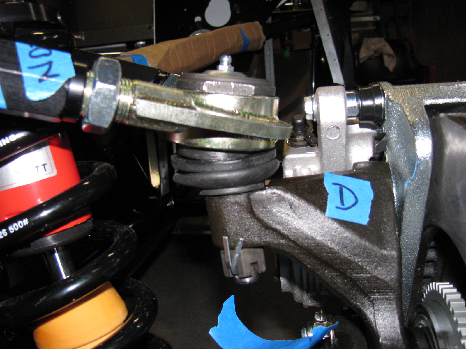
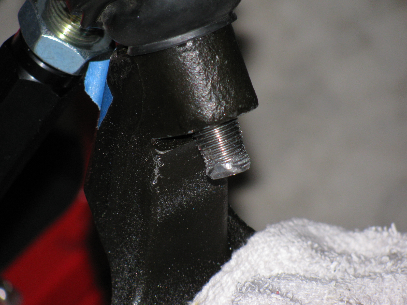
The IRS section is now fully “dry-fit” completed, and the bolts will be tightened to specs in the next work session. One thing that is putting this assembly step on hold are the mounting points for the lower control arms – see the gold color on the right of this picture? That is the mounting bolt and as you can see, there is a lot of empty space between the mounting ear and the thin washer (the manual calls them shims). This cannot be correct, and I need to find what is wrong here. . . .
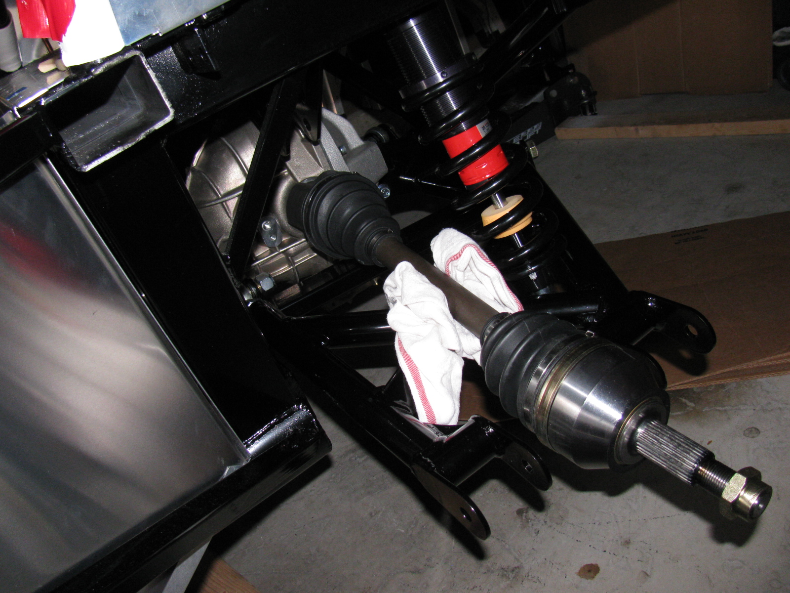
Just after I ordered my Type 65 Coupe kit, I came across a lot of posts on the forums about the IRS shafts (CV joints) coming apart. Those messages made me worry, but when my kit was shipped, the CV axles were on back-order. I called Factory Five Racing technical support, and they assured me that the problem has been fixed.
I am happy to report that my IRS system assembly went very smoothly, after the pumpkin was in place. The CV axles slipped right into the differential, and it felt just like many posts said – you can feel it lock into place. No hammering, no drama and no R- and X-rated words necessary.
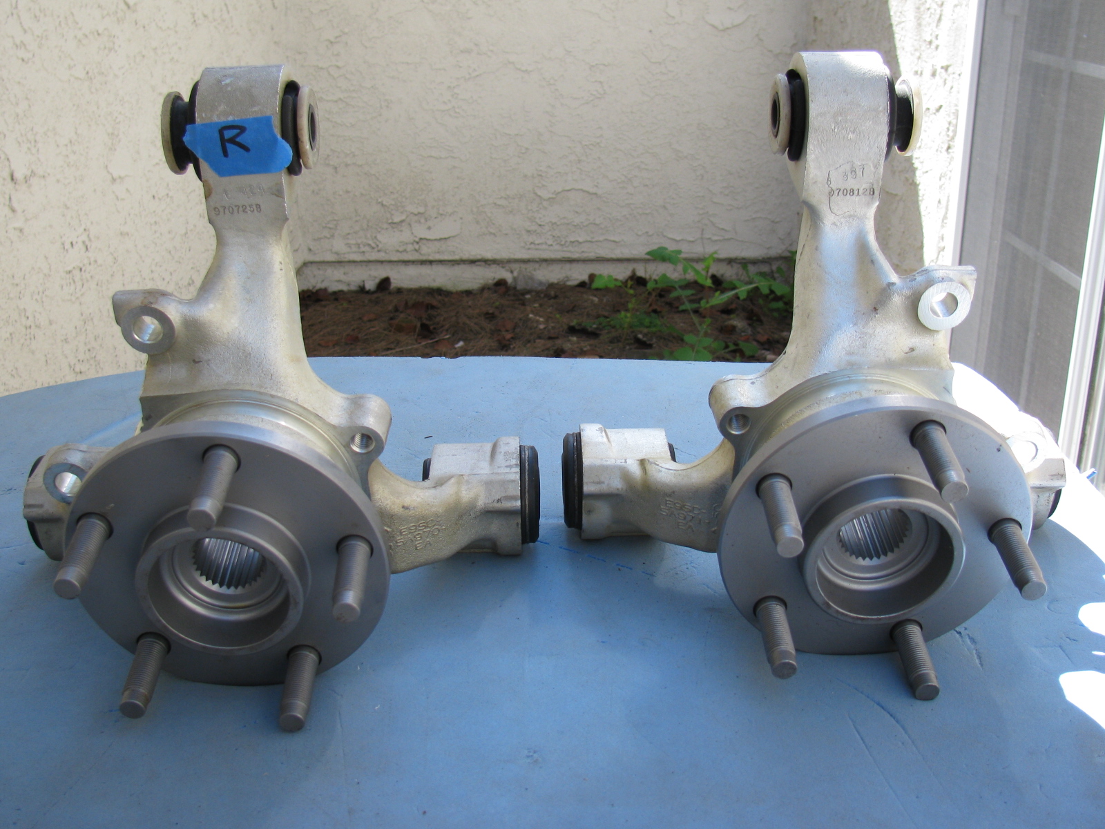
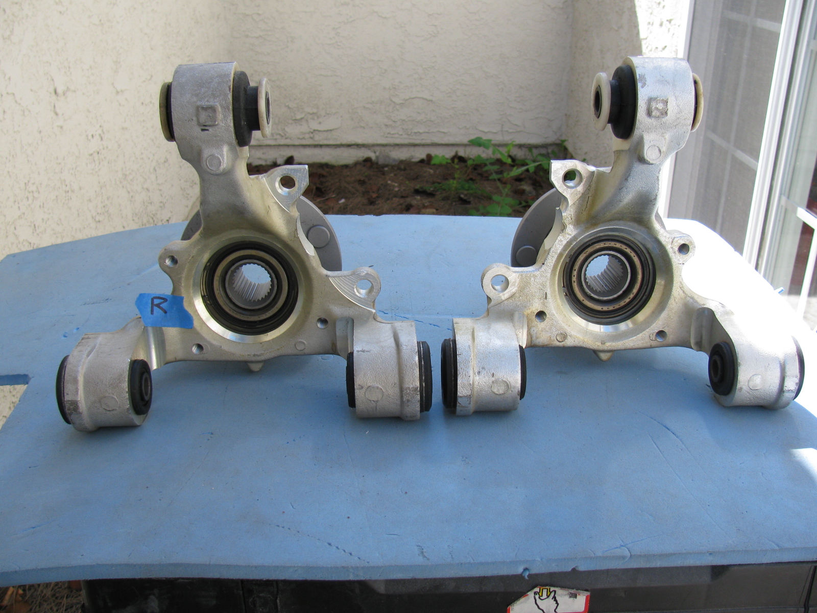
Once again, Chris comes to the rescue by posting images of the IRS knuckles and which part goes on the left side and which one goes on the right side.
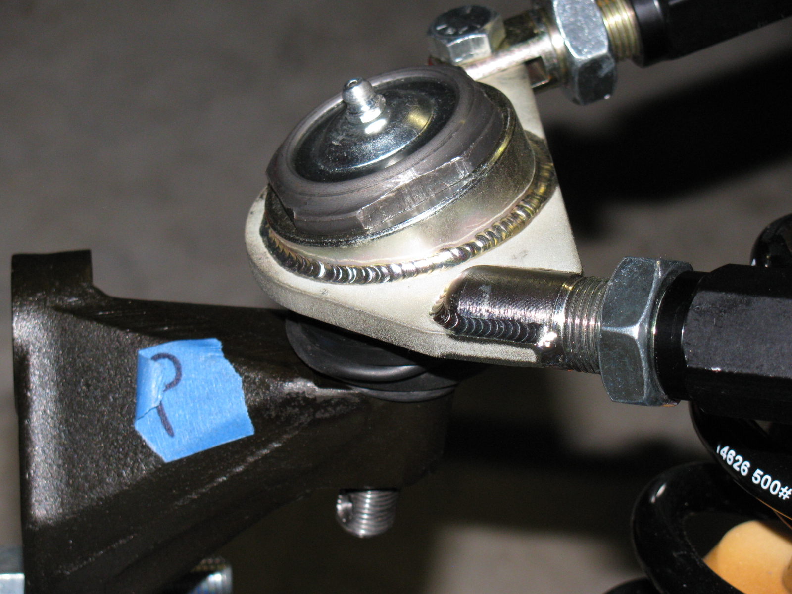
Here are some additional pictures of the IRS components and system . . . . “R” is for Right side of vehicle (passenger side in the US)


Above left: The IRS upper control arm has another pair of small mounting tabs that are not mentioned in the assembly manual. No pictures are included in the manual, either. After a quick search on the Factory Five forum, I found out the smaller set of tabs point downward, and are used for quad shocks – used to minimize wheel hop during acceleration.
Give Me a Brake – Again
Now, the rear brakes are another story. Seems the Factory sent me the wrong rear brake kit. So now I have to wait for the correct parts to arrive, and then have to send the wrong parts back. . . Stay tuned for more . . .
Another Box Arrived this Week – a 10 GHz Slot Antenna
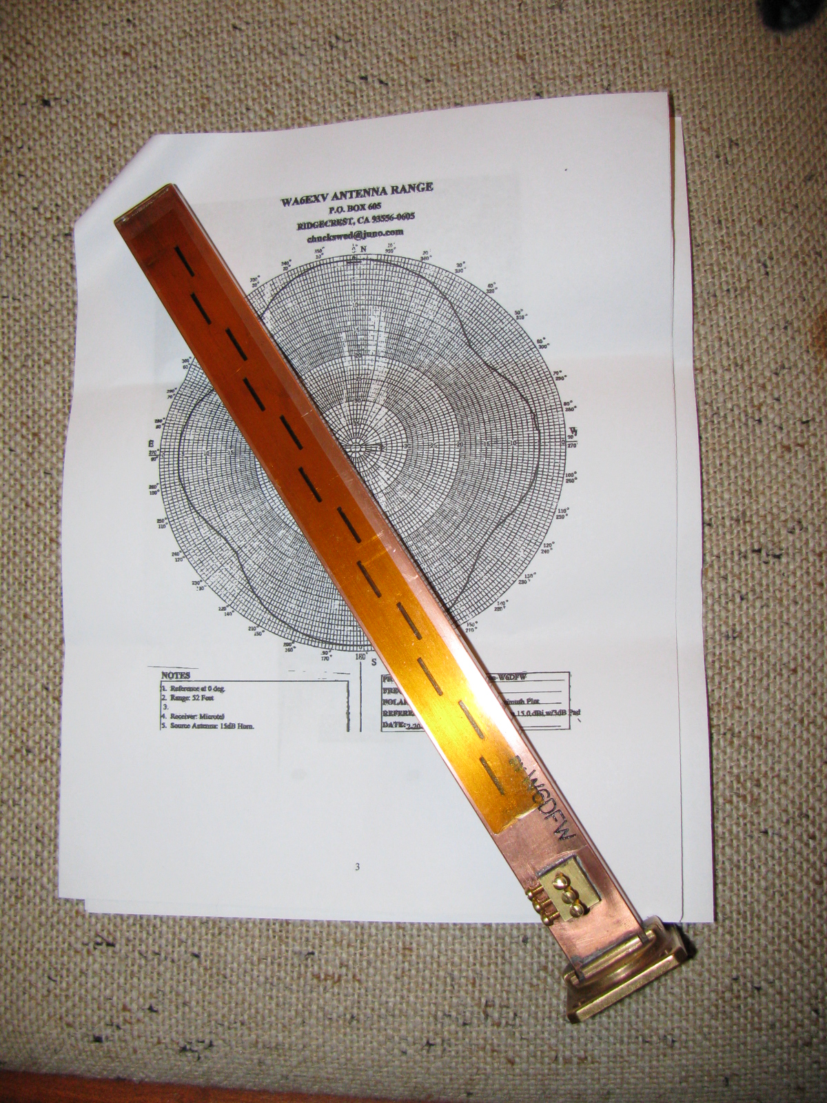
I received this nicely machined antenna for 10 GHz earlier this week. It is made by fellow SBMS member Dan, W6DFW.
Here’s a picture of this omni-directional microwave antenna. The background is the radiation pattern plotted by another SBMS member, Chuck, WA6EXV.
I am planning on using this to make my roving 10 GHz station even more portable, perhaps getting on 10 GHz FM mobile. More on this item and possible applications at station KH6WZ later.

Since the engine is in the middle of my garage, I really need to accelerate my building, or at least, get my chassis ready for engine installation.
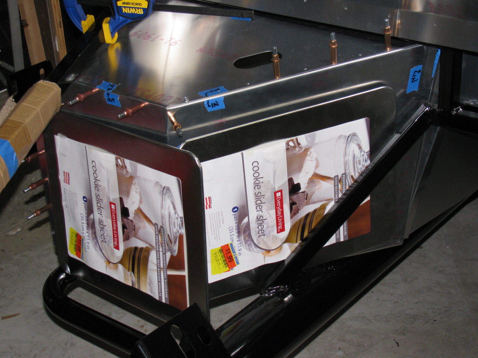
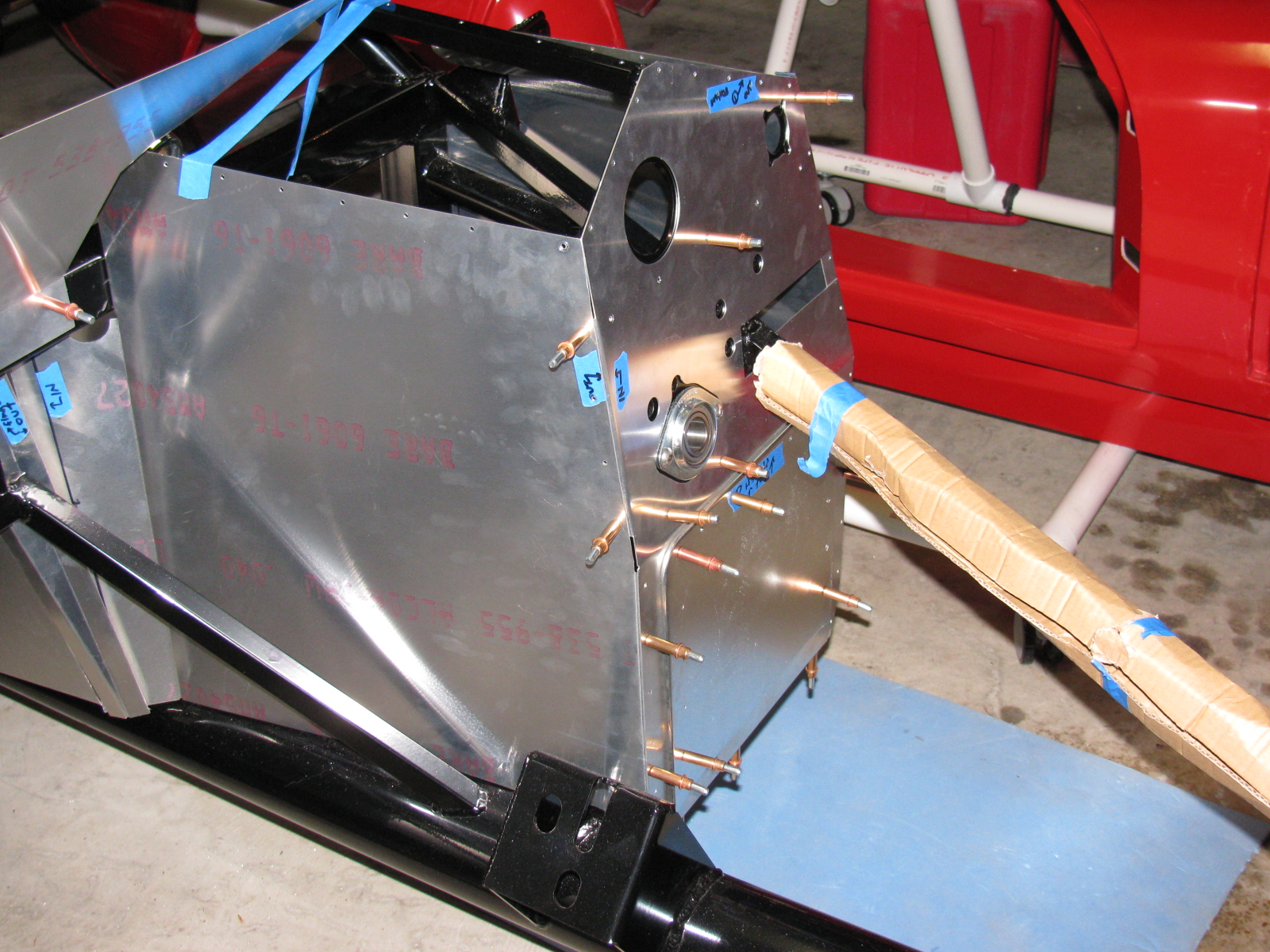
I looked at my cookie sheet heat shields and the mounting locations filled with 8-32 riv-nuts, and thought – shoot, the riv-nuts actually have a shaft that might be used as stand-offs for the shield plates. So I checked the length, and the threaded shafts are about a quarter-inch long, enough to be used as a spacer between the firewall and the heat shield. I may add another quarter-inch in certain places, if there is room.
So I spent a few hours removing all of the riv-nuts I installed a few weeks ago. Good thing I bought several hundred from McMaster-Carr. . . .
At least I am an expert on installing and extracting riv-nuts now.
Rivet Nuts and the Rivet Nut Tool
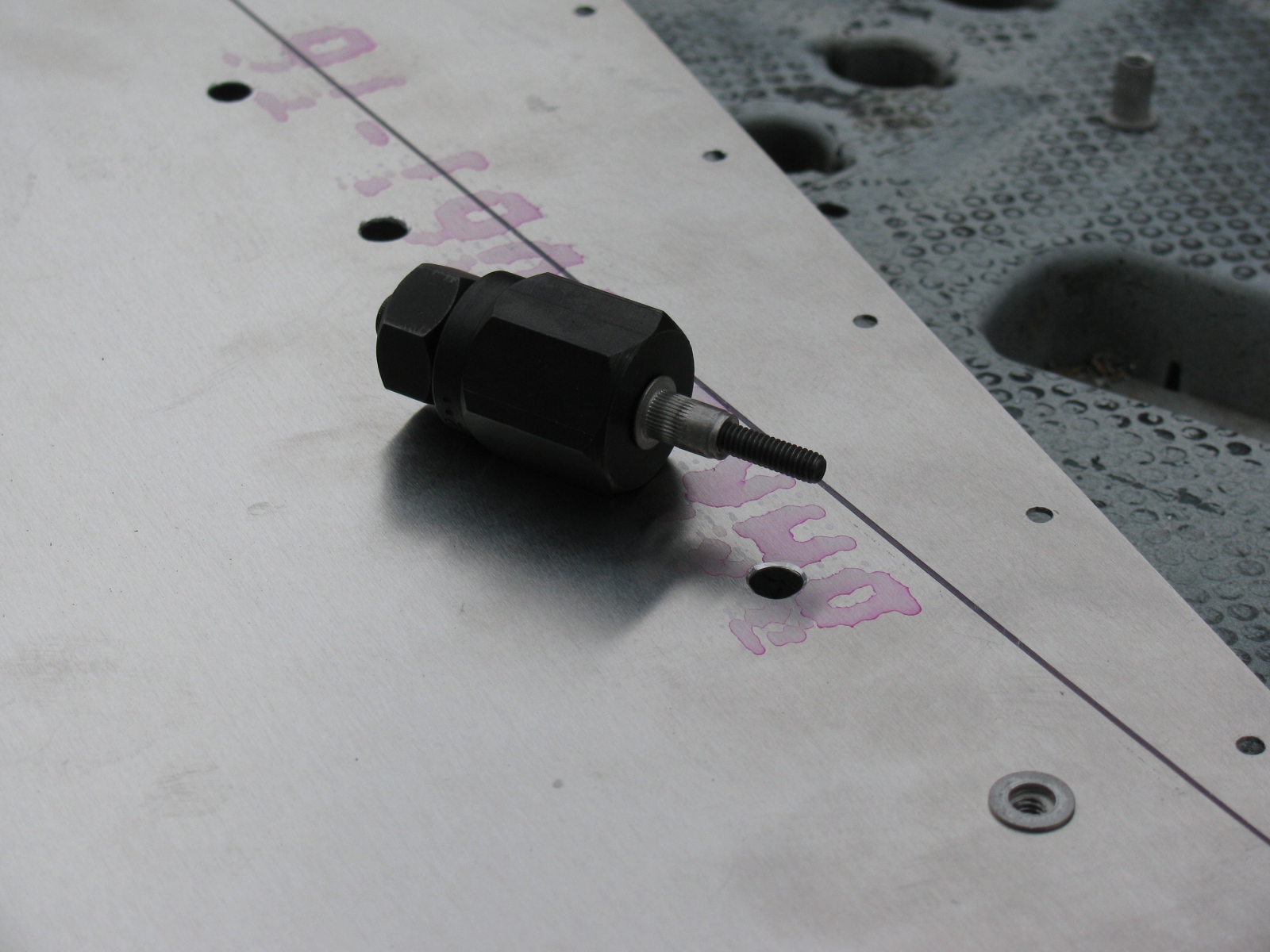
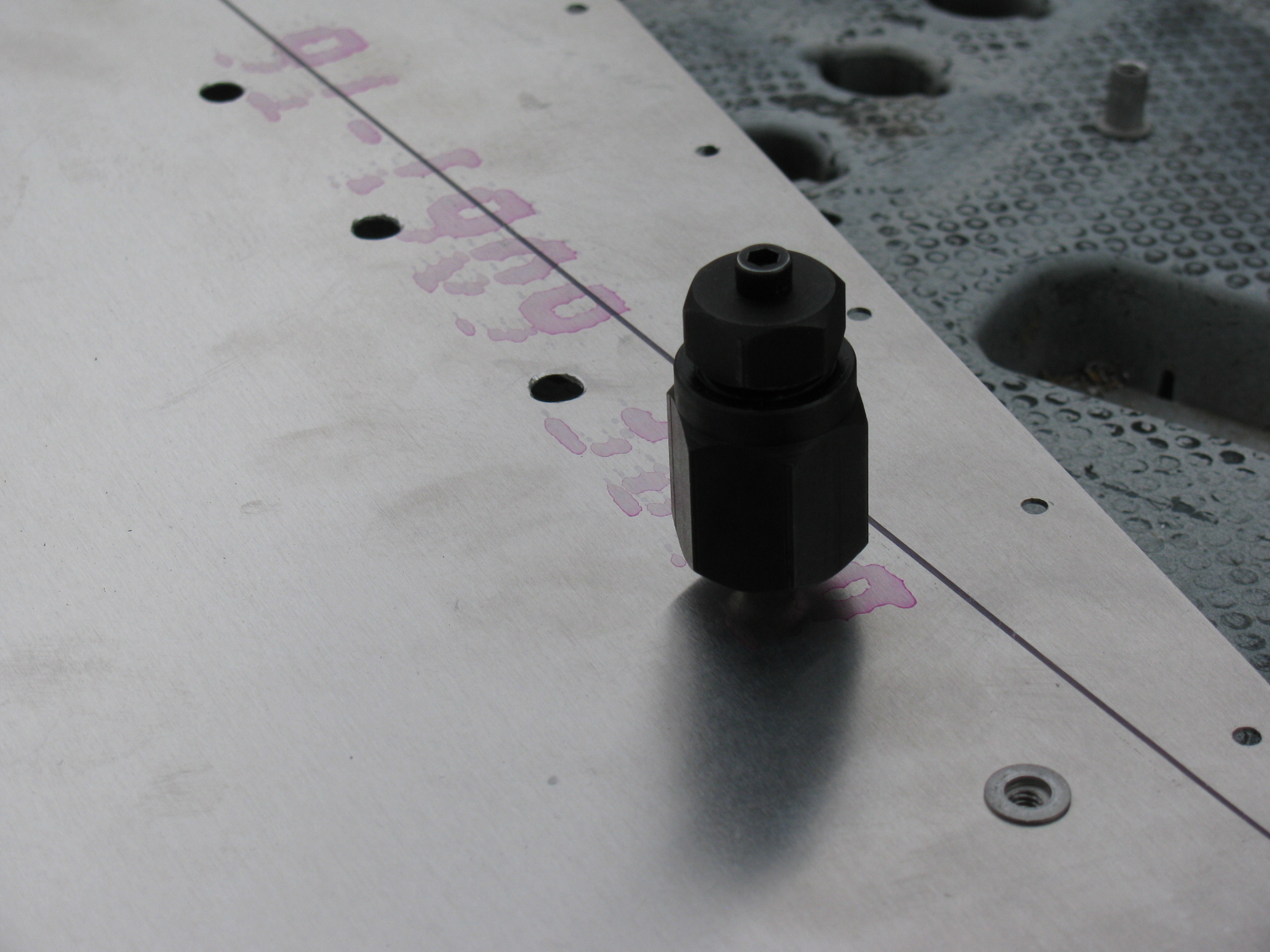
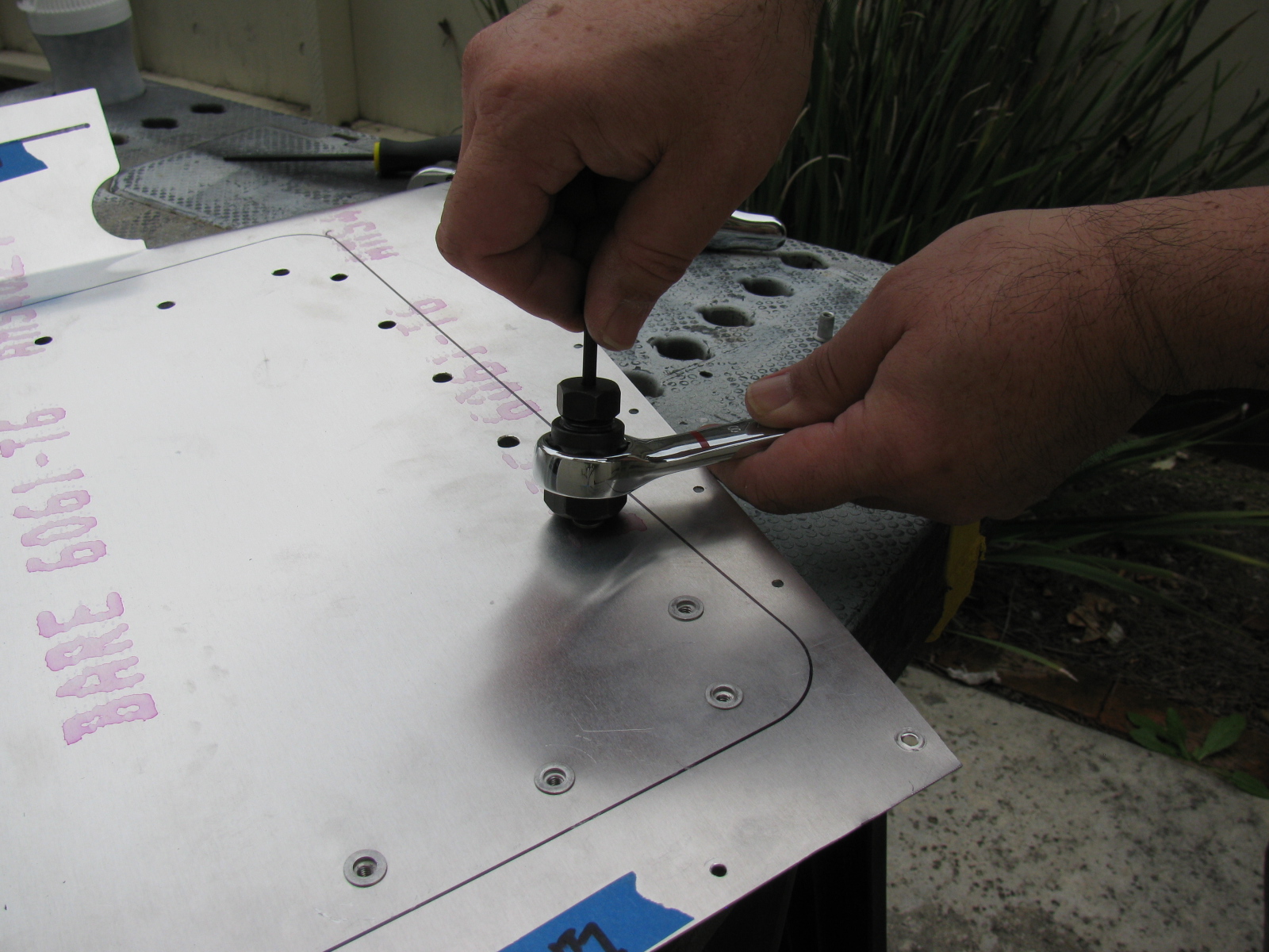
Here are some pictures of the riv-nut tool from McMaster-Carr and how it is used. Riv-nut fasteners are very handy if you need a threaded hole installed into a blind location, or when you do not have access to the back side of a mounting surface. I will use these fasteners for hatches and compartments in the trunk area of the Type 65 Coupe.
McMaster-Carr information
Wrench-drive rivet nut installation tool for 10-24 and 10-32 thread: 96349A203
Wrench-drive rivet nut installation tool for 8-32 thread: 96349A152
Wrench-drive rivet nut installation tool for 6-32 thread: 96349A101
Aluminum heavy-duty rivet nut, 6-32 internal thread, .080″-.130″ material thickness, packs of 25: 94020A315
Aluminum heavy-duty rivet nut, 8-32 internal thread, .080″-.130″ material thickness, packs of 25: 94020A323
Aluminum heavy-duty rivet nut, 8-32 internal thread, .020″-.080″ material thickness, packs of 25: 94020A319


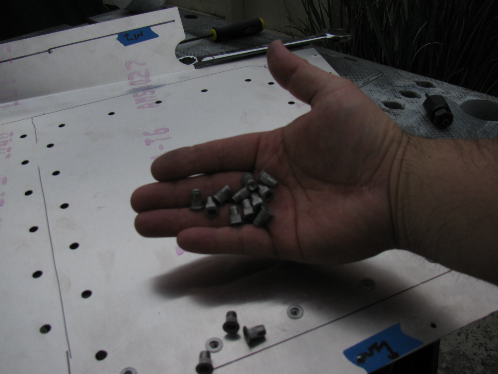
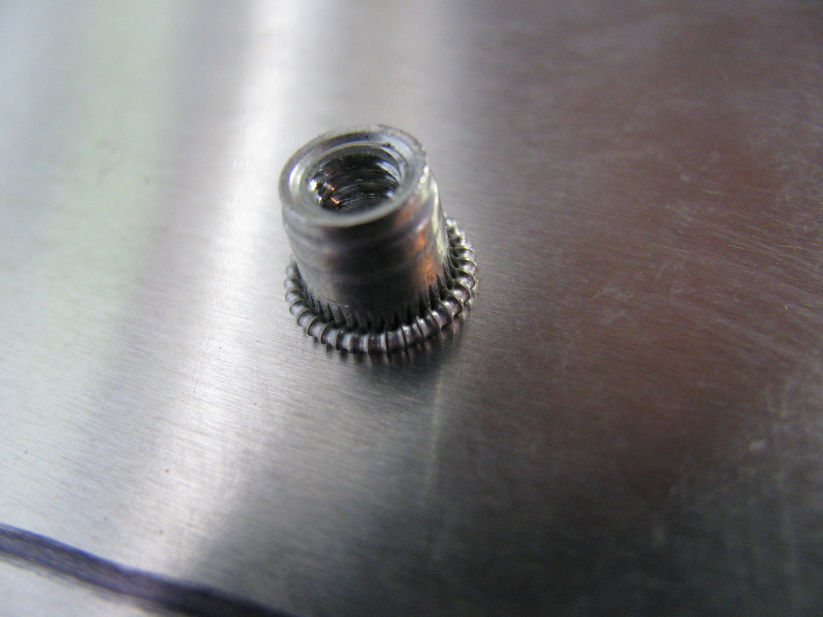
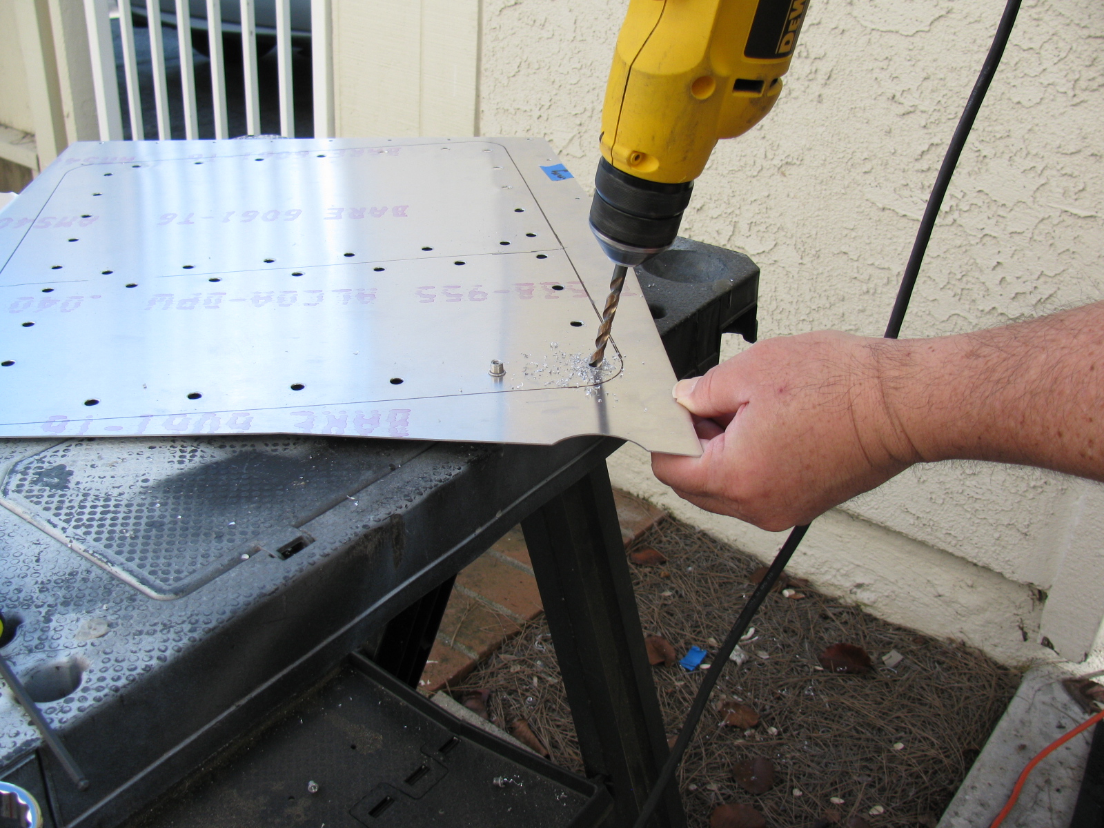
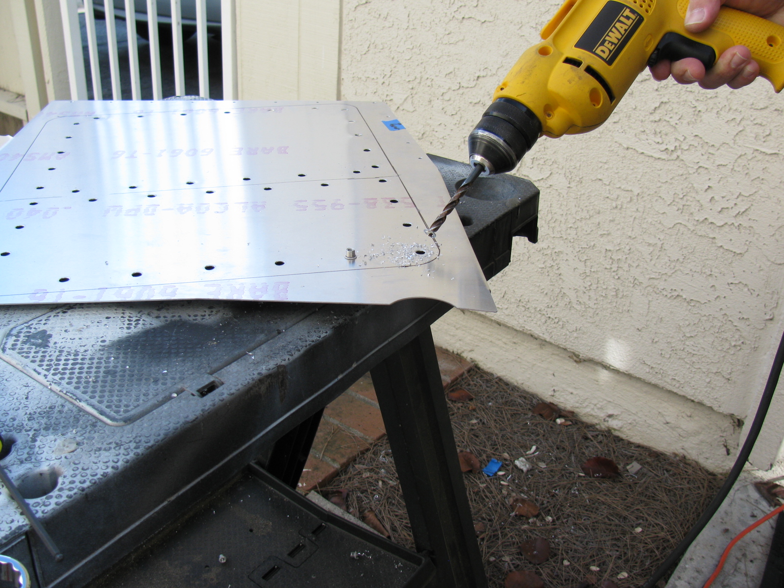
Above left – a picture of a properly installed riv-nut, viewed from the reverse (back) side. At right, a riv-nut improperly installed, viewed from the face (front) side. This one must be removed by drilling the riv-nut out. Below left, use a twist drill slightly smaller than the mounting hole, in this case, a 1/4-inch bit is being used to drill out the riv-nut. By slightly rocking the drill, the riv-nut will break apart and, usually, just fall out of its hole.


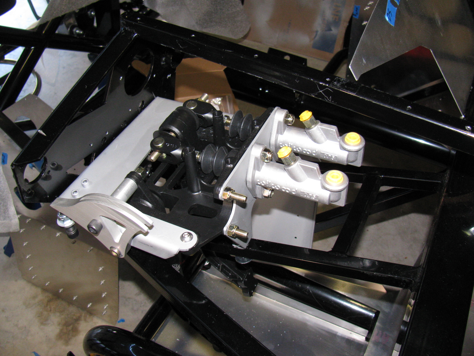
Give Me a Brake: The Wilwood Pedal Box
The pedal box is a challenge to install with the Factory Five Racing Assembly Manual, revision 3E, July 2011 – since there are no assembly instructions for the Wilwood Complete Kit pedal box.
Fortunately, a dedicated Type 65 Coupe builder named Chris has an excellent photo album of his Coupe build, with many detailed images. Without his documentation – it would have been impossible to assemble this part of the kit. Take a look at cbergquist1’s photostream on Flickr.
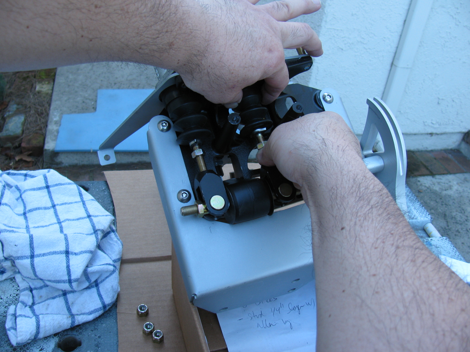
Here are some pictures of my pedal box, including a trouble spot I ran into, and how I had to fix it. . . .


This is the clutch quadrant adjuster (above). This Nylok had to be ground down to fit properly. The hole in the adjuster plate is too close to the master cylinder mounting plate. A better solution would be to eliminate the Nylok altogether and thread the small plate. Then the lock nut and Allen bolt are used to make clutch travel adjustments.


Now I have to find a place to mount the master cylinder reservoir. There are some rare posts about this, but most of them are for the Factory Five Racing Roadster.
I think I will mount mine at or near the peak of the driver’s side footbox/firewall. This location should be away from too much heat, and should be in the clear for fluid bleeding, checks and re-filling. We will see. . .
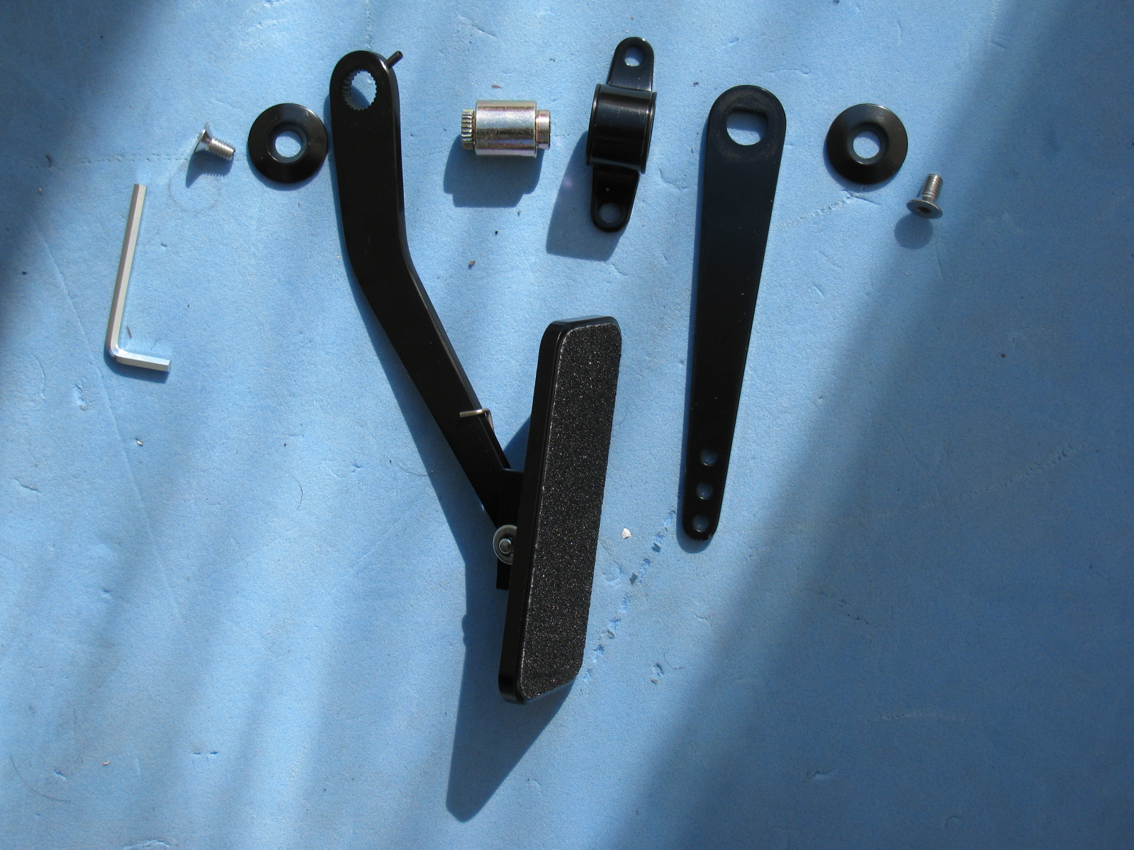
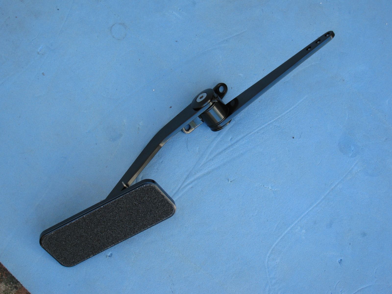
The Gas Pedal


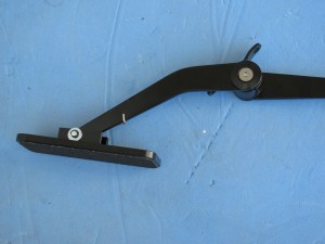

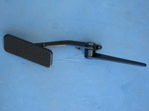
Part of the pedal box area is the accelerator pedal. Again, instructions are very skimpy on how to put this thing together. Here are some pictures of the gas pedal parts and how to dis-assemble the unit as it comes out of the box, and where it mounts onto the firewall area. Adjustments for the pedal box and accelerator pedal will happen later.
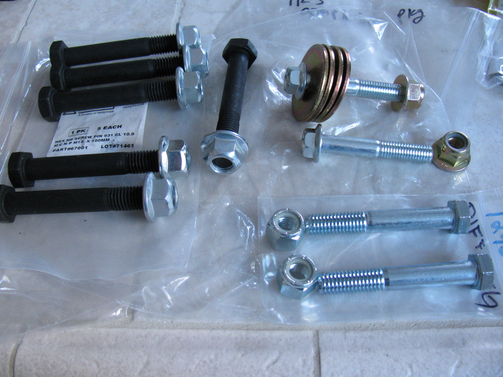
Regarding the two “missing” nuts and bolts for the IRS pumpkin – I found them this morning. Two nylon lock nuts and two bolts (1/2-13 x 3.25-inch) are in the 12438 bag, in Box 11C, IRS STD Width Rear Suspension.
The other two are included in the “IRS Completion Package” and are part numbers 25995 for the flanged locknuts and 14952 for the two bolts. I am not sure why these are metric. . . .
This is what they look like, the nuts and bolts from Box 11C are at the 5 o’clock position.

I received some sad news today from EDN. Eric Lidow, one of the last true electronics pioneers – passed away on January 18. I worked for his company, International Rectifier, from 1998 to 2006, but used IR components in my electronic projects since I was a kid in elementary school. And when I was in the eighth grade, I won the Science Fair, Physical Science Category, with my “Photo Phone” – which used an International Rectifier solar cell in the receiver.
One day at the office, I received a plain envelope with just my name on it. Inside was a hand-written note from Mr. Lidow. He thanked me for “not presenting our products with too much hype.” I still have that note in my files, and will always remember his advice.
Visit the International Rectifier website, a lot of my content is still present in the archives. . .
International Rectifier
The EDN story
The front IFS is still not right, and the responses from the forums and the directions are confirmed by Jason at Factory Five Racing. Now the difficult task involves more un-building and hoping parts are not damaged. The ball joint on the passenger side needs to be removed and the upper A-arm top plate has to be flipped over. This is a direct result of an error in the Factory Five Racing Type 65 Coupe manual (revision 3E, July 2011) on pages 60 and 61 and 63 and 64.
The manual says to install the ball joint into the upper control arm to make “a left and a right.” I did this, and now must dis-assemble one of the ball joints. A new upper control arm is more than $200, so this is a costly error if I am not able to correct this.
The correct orientation is shown on the driver’s side of the suspension. The passenger side is incorrect. This assembly is difficult to describe in words, so it is best shown with pictures.
Here is the driver side showing the upper control arm and the ball joint mount on the plate – see the wedge-shaped, “thicker” end at the apex of the triangular plate? This is correct.


This is the passenger side upper control arm. See the thicker wedge-shape on the opposite side of the apex? This is incorrect (wrong).


I dis-assembled most of the front suspension to get to this ball joint. However, the ball joint fits into the spindle via a tapered hole. . . meaning that some force must be applied to remove the ball joint stem from the spindle. I started by tapping – then pounding – with my plastic hammer, since I did not want to damage anything. No good. I changed to a scrap of oak and my ball-peen hammer and hit it hard for several minutes. Still no good. I got rid of the piece of wood and really slammed with the ball-peen hammer. Finally, the stem popped loose.
Of course, this created a mushroom on the ball joint stem, and it would not come out of the hole. I filed around the mushroom and finally separated the ball joint from the spindle. I should be able to file or grind the stem so the ball joint can be re-used.

Mushroom on the stem!
Removing the ball joint requires dis-assembly with 450 degrees F (since I used Permatex medium strength thread locker blue), a vise and a big wrench with lots of grip and torque.
I tried several times, but my vise just isn’t gripping the ball joint properly, it slips off. I need a bigger vise and a torch for this. My bench vise is too small.
Cutting the Dash
Since I could not remove the ball joint, I decided to move to another part of my project – cutting the dashboard in half. This is a popular modification that will increase access into the area between the dashboard and the firewall. This area will soon be stuffed with wiring and air conditioner ducting, so the dashboard had to be cut sooner or later.
I wondered how this was done, should I leave a “lip” on one of the sections so I can patch the panels together? Or do I just slice along the fold? What is the safest way to do this with my power jig saw?
It turned out to be easier than I thought. Here are some pictures of the cutting operation . . .

I used some duct tape and a wood scrap to hold the dashboard in place for the cut. My trusty Makita power jig saw did the trick.

I will use a piece of aluminum angle stock to mend the two sections together.
I may make a new dashboard front panel, especially since the original one has several things wrong. For example, I ordered the “modern gauges” option. There is no mention that the modern gauges are smaller than the vintage gauges. The dashboard comes with cut-outs for the larger gauges, and a triangular-shaped adapter plate for the smaller gauges. Also, the steering column hole is in the wrong place, as mentioned in a previous posting. If I knew this was going to happen, I would have ordered a plain, non-drilled dashboard – so if you are planning your order – consider asking for an un-cut, un-drilled dashboard and make custom cut-outs where you want them.
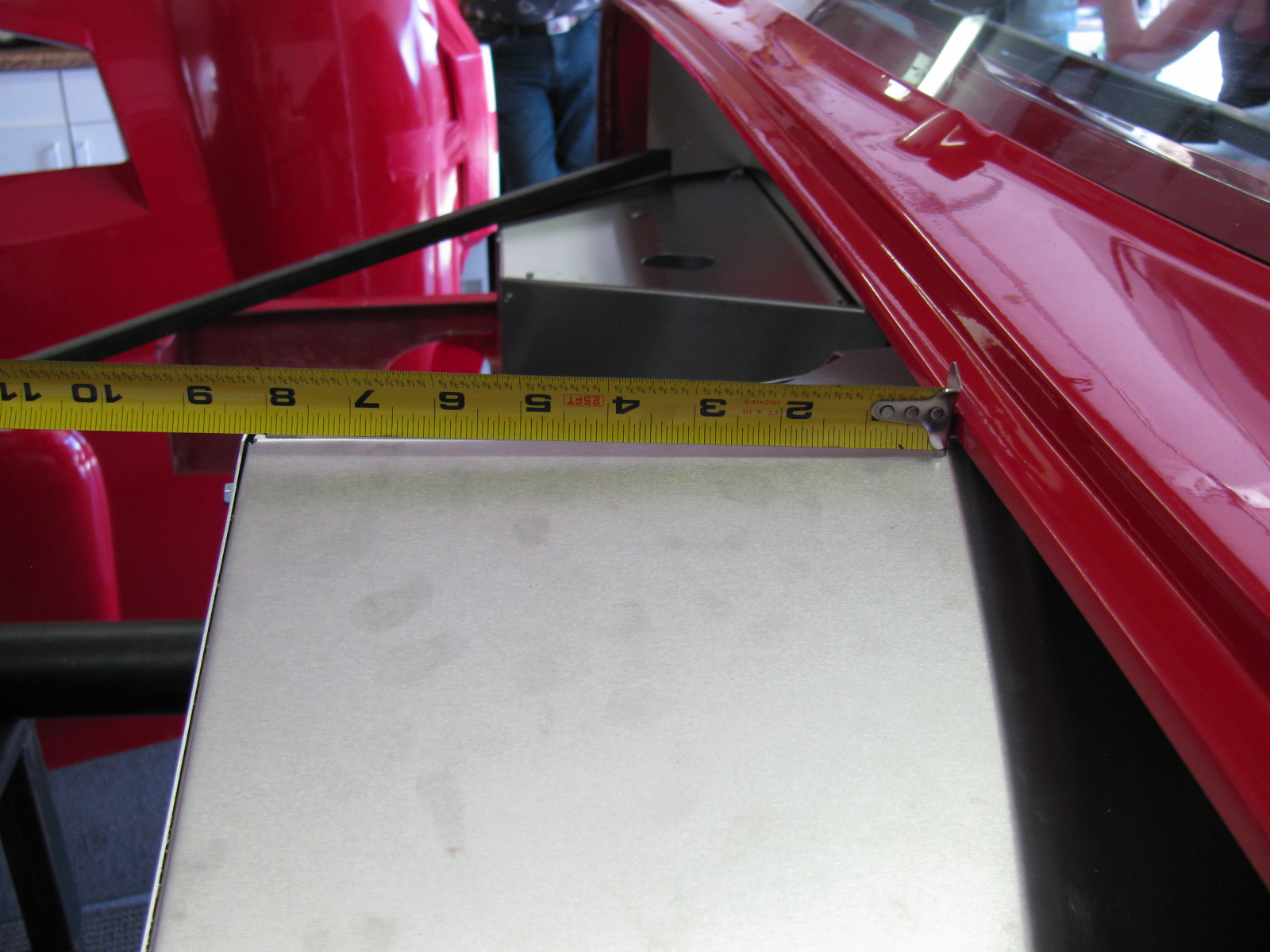
Cookie Sheet Heat Shields
A few weeks ago, I found these cookie sheets in the close-out bin at the grocery store. They have nicely rolled edges and they happen to be almost the right size for the footboxes.


The amazing part about these cookie sheets is the angle at one end – it exactly matches the angle at the back of the driver-side footbox. I will mount them with 8-32 machine screws, spacers and locking nuts. I will also add a layer of insulation (Cool-It mat) between the heat shield and the footbox panels.
I am no longer sure if I want to use the Rust-Oleum BBQ paint for my firewall and other panels. I did a paint test this weekend, and the paint is quite soft, and scratches easily.
The Battery Mounting Plate
After noticing how soft that BBQ paint is, I decided to do some more paint testing. This is the battery mounting plate. It is made of steel, and it is already starting to rust. So I decided I should paint this part and the other steel items soon.

I used Rustoleum Appliance Epoxy paint for this test. This is my standard paint for radio and electronics projects. The finish is very hard and glossy, the cured surface is washable and no primer is needed. However, it is not meant for heat, the maximum temperature is 200 degrees F.
I prep the surface by scuffing the surface with 80- or 150-grit sandpaper on a random orbit sander, followed by a dish soap and water wash. I apply the paint in three or four very light fog coats and the surface becomes slightly textured. I may go with this paint, if I can find a suitable color. The last time I looked at spray paints, this appliance finish comes in white, almond and black. Too bad it does not come in silver or gray.
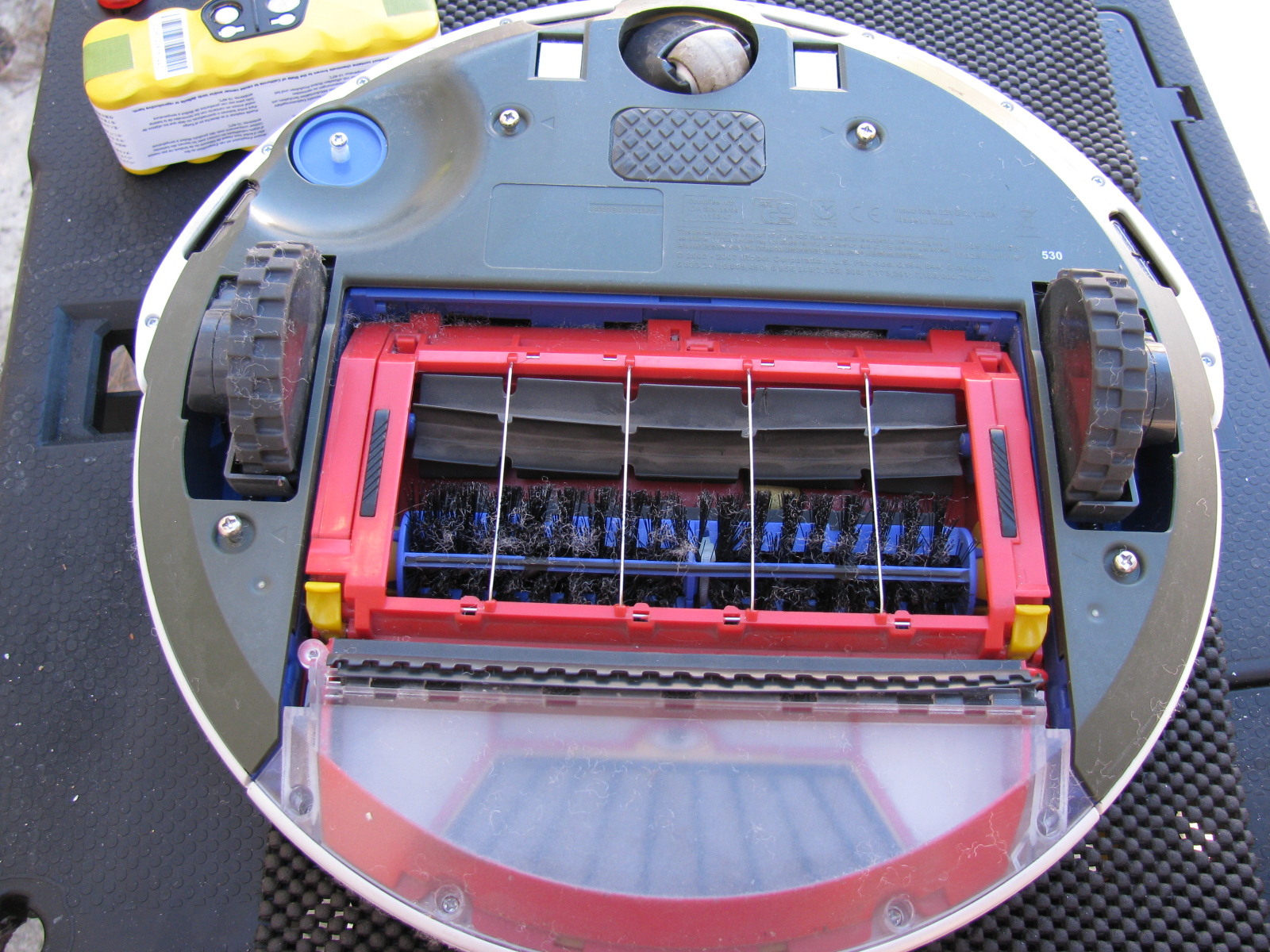
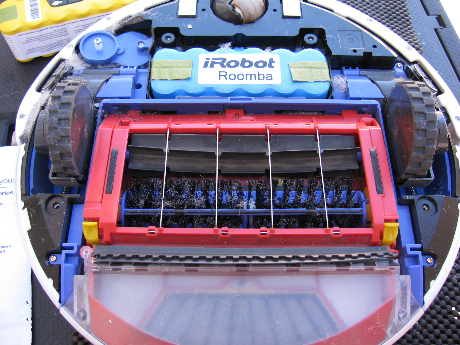
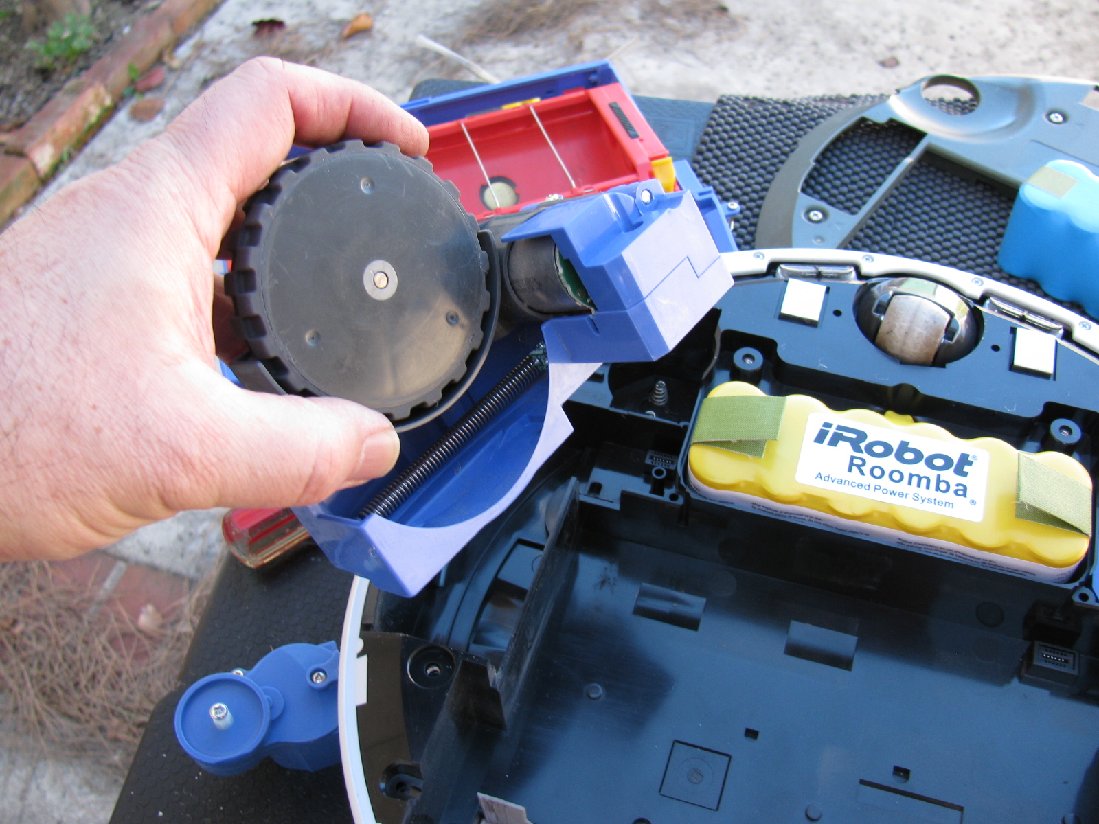
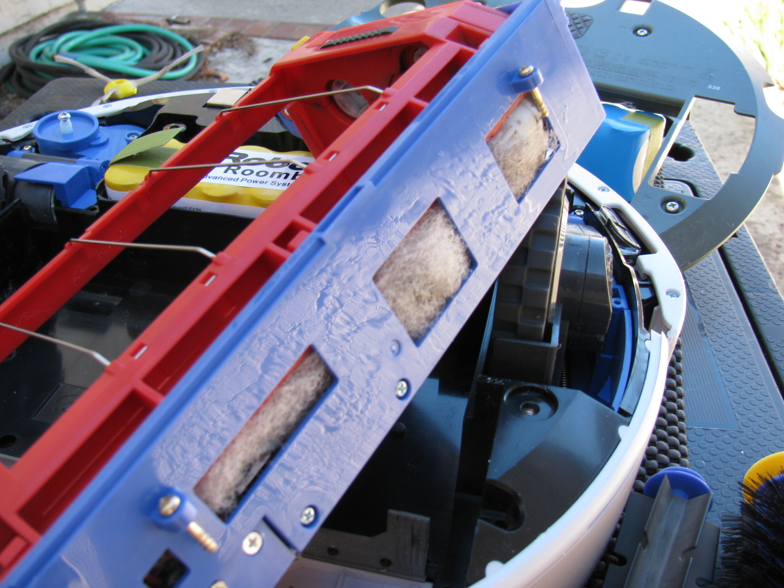
Roomba Battery-Ectomy – Vacuum Cleaner Battery Replacement
After almost three or four years, the battery pack in my Roomba 530 stopped taking a full charge. I re-newed the charge cycle several times, but the Roomba would run out of charge before completing a single room. So I performed a battery-ectomy on the Roomba. It needed a good cleaning inside the chassis anyway, so this was something I needed to do. You can see the debris inside the mechanisms that are impossible to clean unless you open the case. I used my shop vac to suck out the junk inside the various nooks and crannies inside the Roomba. The new battery has a larger capacity and should provide a longer running time. This will be good, since Roomba will help increase my time in the garage and other non-house cleaning activities. . . .
Here are some pictures. . .


It’s been cold in the garage lately (50s-60s), but I wanted to get some more work done on the Coupe. My 302 is scheduled to arrive this month, but I have a lot of work to do before I can install the engine and transmission. This is one of those rare times when I can tell a supplier to take their time.
Back to this weekend’s update: What’s cookin’. When I lived in a small townhouse, I used to make a lot of meals in a Crock Pot, and noticed a few things: First, it was very handy to fill the thing up with various meats and vegetables, turn it on, go away for a few hours and dinner would be ready. Second, the smell was always wonderful. And third, it actually made the house a little warmer.
I decided this third effect of Crock Pot cooking deserved a try in my garage – and it worked. In the morning, I filled the Pot with my universal minestrone recipe and added some leftover spare ribs from the freezer. I call it “Spare Rib Minestrone.” The recipe appears at the end of this entry. It is roughly based on a minestrone recipe from Fat Free, Flavor Full: Dr. Gabe Mirkin’s Guide to Losing Weight & Living Longer. And it is pretty tasty. It made the garage a few degrees warmer, too. Here’s a picture. . .

Cooking in the garage – a tasty alternative garage heating method!
Halibrand-Style Wheels Arrived
The Factory Five Racing Halibrand-style wheels are BIG and beautiful. Wheels are 17 x 9 in front and 17 x 10.5 in the rear, and feature a spin-off hub. I am still not completely sure what tires will go on these rims, my preliminary choice is a set of Goodrich Sport-Comp 2 or something like that. This may change as I get a little farther along on my build.


The Steering Rack
I decided to see if I could finish the front end this weekend, especially since a lot of the back-ordered items arrived – I finally have a complete set of parts for my complete kit!
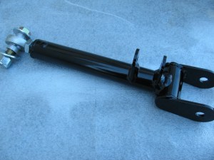
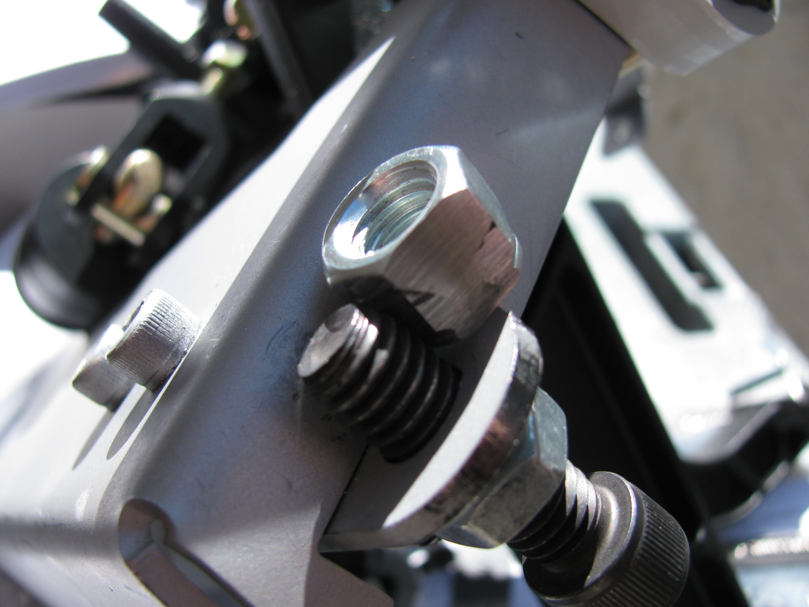
The steering rack is a non-powered unit made for the Mustang. Like many others, the mounting ears were too close together and I had to spread them out by a little over a quarter of an inch. I tried to use my pipe wrench trick, but the tabs are a little small and I wasn’t able to exert enough torque to move them. Doing some research on the Factory Five forums, I kept reading about people using a nut and bolt to spread mounting tabs wider. I finally found a post that included a picture of this, for future reference, it is located here, and I am posting photos and captions on my site as well so it may be easier to find. It’s a pretty neat trick, although no one says anything about the mounting tabs springing or bending back into their original position – you have to “over-bend” the tabs in order to make the part fit.
Here is my version of the mounting tab spreader tool using threaded rod, washers and nuts – I used 1/2-inch all-thread, since the 3/8-inch rod seemed a bit flimsy:

This really didn’t work too well, the tool needs another nut to hold it securely.

Like this

In the photo above, the open end wrench is being used to spread the mounting tabs outward. If the mounting tabs need to be smaller/tighter, move the washer and nut to the outside of the tab, and tighten the nut – squeezing the tabs closer together.
For the steering rack, I ran into another problem – that turned out to be a non-problem. As you can see here, after spreading the tabs out, the rack fits between the ears – but the holes on the passenger-side need to be moved about an eighth or a quarter of an inch to the left. After thinking about how long this will take using a rattail file, I took a break and thought about the steering rack. The driver’s side mounting tabs had a slot on one side – how come I am not able to move the rack over towards the driver side of the chassis?
The answer is, of course, yes, the slot is just enough to make the rack fit nicely. I used a punch and a mallet to move the rack into position. Success!

Compare the hole on the left (I used silver marker to show where to enlarge the hole) and the slot on the right. No reaming needed – I used a punch and a mallet to move the steering rack into place.
So now the tie rod ends have to be connected to the steering arms. But here is another problem – the driver side tie rod is too long – can I just get a hacksaw and cut off about an inch, as shown by the blue tape?

The driver side steering rack tie rod seems too long – but wait – something is amiss. ..
I decided to stop the steering rack installation at this point and get some answers before cutting the tie rod – because, as Norm Abram always said, “Measure twice, cut once.”
I came across the Summit Racing – Factory Five Racing Roadster build today – and there is a nice picture of the steering rack-tie rod connection posted here – this is for a Roadster, but I think the Coupe shares the same configuration. I have to give F5R a call to verify something – in the Roadster build, the steering tie rod to steering arms are upside down compared to my “dry fit” – Do the Coupe tie rods mount the same way? Also, the Summit Racing car has two lock nuts for each tie rod – my kit came with one lock nut for each side. The manual does not show the ends of the steering rack – poor photo-cropping.
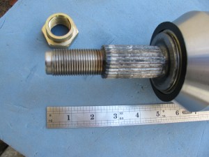
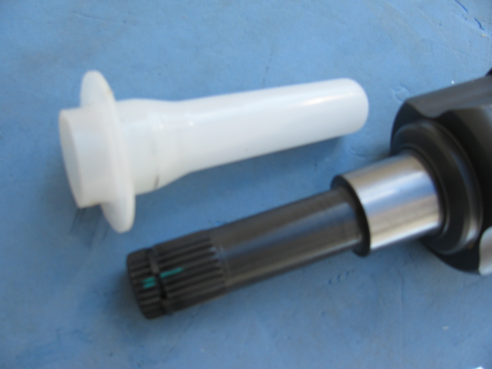
Getting the Shaft
I did some test-fitting of the steering shaft – after some head-scratching moments, I figured out that I needed to remove the adapter that came with the lower end of the steering shaft, and replace it with another one, from another box of stuff. The length is just right, I have seen some early posts about the steering shaft being too long.
But I ran into another problem – the shaft does not come through the dashboard in the correct position. It is not as bad as some others I have seen, but still is quite a ways off. I am not sure if I can just cut the dashboard hole bigger to allow the shaft to come through, and patch the spaces or – what. More fiddling is needed.
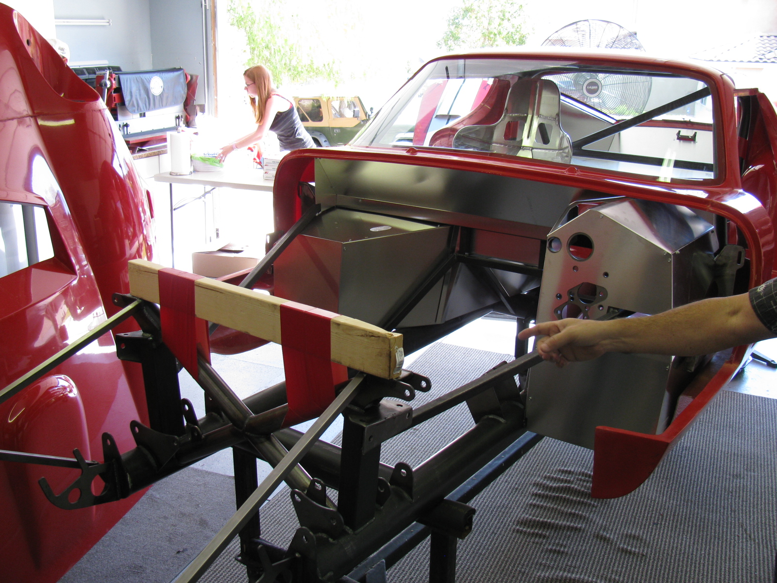
Floor and Footbox Fitting – Passenger Side
I decided to do some more sheet aluminum work – this time, fitting the passenger side floor and footbox. Using the same technique as the trunk floor, I cut the passenger floor into three pieces. After the cutting, I noticed that I could have done this with only one cut, but the three pieces will be OK. I kept the left side un-cut, since it may be seen when the car is done. (I am not sure if I will apply paint or put carpet on the transmission tunnel area yet.)
At this point, everything is being held in place with Cleco pins. I want to test-fit, trim, drill and de-burr all the aluminum panels first, then apply paint – or powder coat them.
So although I think I did a lot of work on the Coupe this weekend, a lot of it does not seem to show. It still does not look like a car yet.

Cutting the passenger side floor.

Passenger side footbox – another jigsaw puzzle!
Something is Making Me Go – “Hmmmmmmm”
I noticed and wonder why the passenger-side side body mount area sheet aluminum is different from the driver-side side body mount area aluminum – take a look:

Driver side – side body mount near the footbox. . .

Passenger side – side body mount area, near the footbox – see the difference?
Here’s another look:

Driver’s side

Passenger’s side. . .
This is making me go, Hmmm. Or more like Arrrrrg.
Season’s Greetings
Somewhere during the weekend, I installed my Christmas lights. I decided to cut back this year, because of all the work I am doing on the car. My “Ho Controller” and box of new lights and other parts I bought last year will have to wait until next year. In the meantime, here is a shot of my display. One of my Universal Rules for events is: “Everything you setup must be taken down and put away.” So many people spend hours and days – or even longer – putting up such decorations. My setup: less than 10 minutes to deploy, and even faster to take down!

Before I forget – here is the Spare Rib Minestrone recipe:
Spare Rib Minestrone
Yield: 6 servings
1 Large onion, chopped
5 cloves garlic, smashed
2 celery stalks, diced
2 cups of chicken stock
1 28 oz can of crushed tomatoes
1 tsp oregano
1 tsp basil
1 can pinto beans
1tsp red pepper flakes
6 small red potatoes, diced
1 large zucchini squash
Some leftover spare ribs, with BBQ sauce
Put everything into the Crock Pot, with the leftover ribs on top, surrounded by the vegetables. Put the Pot on High for about 6 hours or until the vegetables are tender. Based on the Primo Minestrone recipe by Dr. Gabe Mirkin, MD in Fat Free, Flavor Full
The San Bernardino Microwave Society (SBMS) had a Christmas party this past weekend, and it was a good break from doing sheet aluminum work. The event seemed smaller this year, several of the usual suspects were not able to make it. There was lots of food to share and gifts to exchange. Happily, regular guests Mel WA6JBD and his better half, Tisza KI6DBR came and brought their usual homemade treats, including Tisza’s famous chocolate truffles, microwave dish cookies and a chocolate sculpture. This year’s sculpture was a 10GHz horn and a section of waveguide. And yes, they really do work at 10GHz. Mel measured the return loss of the horn and waveguide and reports more than 17dB or something like that – pretty respectable for an edible 10GHz antenna.
Here are some pictures of the event. . .

Where else but a ham radio Christmas party would one find a 10GHz horn and waveguide made of chocolate – that actually works

Tisza’s homemade chocolate truffles – Yum!


Gift exchange crowd
What in the World is That?
After the party wound down, I stayed to get a closer look at Dennis’ new camera. It does not look anything like a camera, but it really shouldn’t because it makes images in a whole new way and enables a whole new way to enjoy still images. I thought it looked more like a kid’s kaleidoscope, rather than a camera.
The camera and lens system optics look very simple. And that is one of the points: You do not need fancy telephoto or macro lens capability. It is done in software. There are no fancy controls or buttons, only soft pads on the rubberized parts of the case. There is a power switch, a zoom control and a shutter release. An LCD with touch screen is on the back. Here are some pictures of this new gadget.

WHAT is THAT!

The Lytro camera. At left is the lens cover, it attaches magnetically. That’s an item that will be lost immediately. Center, the camera, showing the front glass and lens. Right – a tripod adaptor.
As I mentioned on my LinkedIn update, the Lytro camera introduces a paradigm shift in the way we can look at still pictures (pun intended, sorry). At first, I thought this camera simply used some sort of image processing to “fix” images, simple things like contrast and color adjustments and maybe some image manipulation, like PhotoShop. But then Dennis said that you can change focus and “raw image” features, like zooming in – after the image is stored on your computer.
The images are not jpg or other familiar formats – but then – these are not ordinary images, either. You can actually change the depth-of-field – change the point of view of the image.
Watching some of the demos on the Lytros website made me think of scenes from the TV show “CSI:” because you can see an image captured by the camera, and you can actually zoom and move around the various places on the image, and see what else the camera captured.
Visit the Lytro website, pictures and demos and details are worth closer examination. Unfortunately, I don’t have any Lytro images to share – yet.
The Coupe Goof
The day after the party, I went back to work on the Coupe. Something bothered me as I looked at the images and some postings of other builders. The driver’s side footbox and the front, where the pedal box mounts, looked different than mine. And I found another driver side footbox front panel in my box of aluminum parts. I looked at the part number of the “extra” footbox front (15312) on the packing slip, and noticed the description: “Driver Footbox Front Wall, Coupe Wilwood Pedals.”
Argh. Since I have the Complete Kit, it came with a Wilwood pedal box. Part of the confusion is the way Factory Five Racing packed the sheet aluminum – the major parts are held in place on the chassis and are shipped in place. This would be fine for the builders using a donor Mustang pedal box, the “Basic Kit” version.
So, I had to remove the driver side footbox front panel and replace it with the proper one. The good news is that I had all these things in place with Cleco fasteners, not rivets and silicone. And, I used the old panel as a drilling guide for the new panel. Now I have a spare sheet of aluminum I can use for – something. Hatch covers, maybe.

On the left is the wrong driver side footbox front panel. This is the one that is shipped in place on the chassis. The one on the right is the front panel for the Wilwood pedal box. Good thing I didn’t silicone and rivet that panel!

Disaster averted – the wrong footbox front panel was removed and replaced with the correct front panel for the Wilwood pedal box.
Nov. 29, 2012 by Glenn Bischoff in Urgent Matters
Ham radio, public service and super storm Sandy. . .
One fact in Glenn’s article needs correction:
ARRL is the American Radio Relay League. I worked there in Newington, CT many years ago…
Singing the Praises of Unsung Heroes
Thanks to Jason and Rick at The Factory – and Dave Smith – president of FFR – for the GREAT 50-50 sale – I have configured and ordered my 65 Coupe component car. I am now looking for a Ford Racing 302 V8, with electronic fuel injection and a Super T5 transmission to complete the list of ingredients.
Delivery is scheduled for late September. I am planning to hold a “Delivery Party” with the local F5R builders and some other friends in the area. Probably another great opportunity for another Networking / End of Summer / Coupe Delivery BBQ!
I will be documenting the build with still images and video, too – so stay tuned!
A gallery of these beautiful cars can be found here:
http://www.factoryfive.com/galleries/type-65-coupe/


