Archive for the ‘technology’ Tag

Some additional information to supplement my presentation called “Building and Contesting on 10 GHz.”
This is not a complete listing of “microwave amateur radio knowledge” but it is a one-page resource to help you get started.
The first thing I would recommend is to find and join your local VHF and above ham radio club. There are clubs that focus on microwave technology and operating all over the world – find yours to meet new people, learn new things, get a rig going and join the fun!
Microwave Update (MUD)
One of the best places to meet active microwave band hams and learn more about the SHF ham bands is the Microwave Update (MUD). The event is sponsored by various clubs around the USA.
The printed papers (Proceedings) are available from the Lulu print-on-demand service.
The IF Radio

All-mode transceivers become the IF on the uWave bands
All-mode transceivers become the intermediate frequency (IF) stage in a microwave transverter system. I like to call the IF rigs the human to “transceiver interface” because this is the unit we use to tune the operating frequency, hear through the speaker and transmit audio via the microphone. Usually the IF radio also initiates the receive to transmit change-over as well.
It is important to know that IF radio performance does not affect overall performance on the microwave frequency.
In other words, fancy filtering, special ovenized oscillators and even CW or SSB filtering are not mandatory. While all those features and functions can enhance enjoyment, it’s the transverter at the microwave frequency that determines performance for the microwave station. In fact, I have two Yaesu FT-817s. One is equipped with CW filters, one is not. Sometimes, because stations often drift, the IF radio with the filter may not be able to hear the other station because the stations have drifted beyond the receiver passband. I normally bypass the filter on my IF radios.
But this is also a good thing, since it means inexpensive and even used VHF, all-mode rigs can be used.
Also remember, for transverter use, the transmit power from the IF rig is on the order of a few mW or less. So, if you are able to find, for example, an all-mode 2m rig being sold “for parts or repair” – that may be a viable candidate for an IF radio.
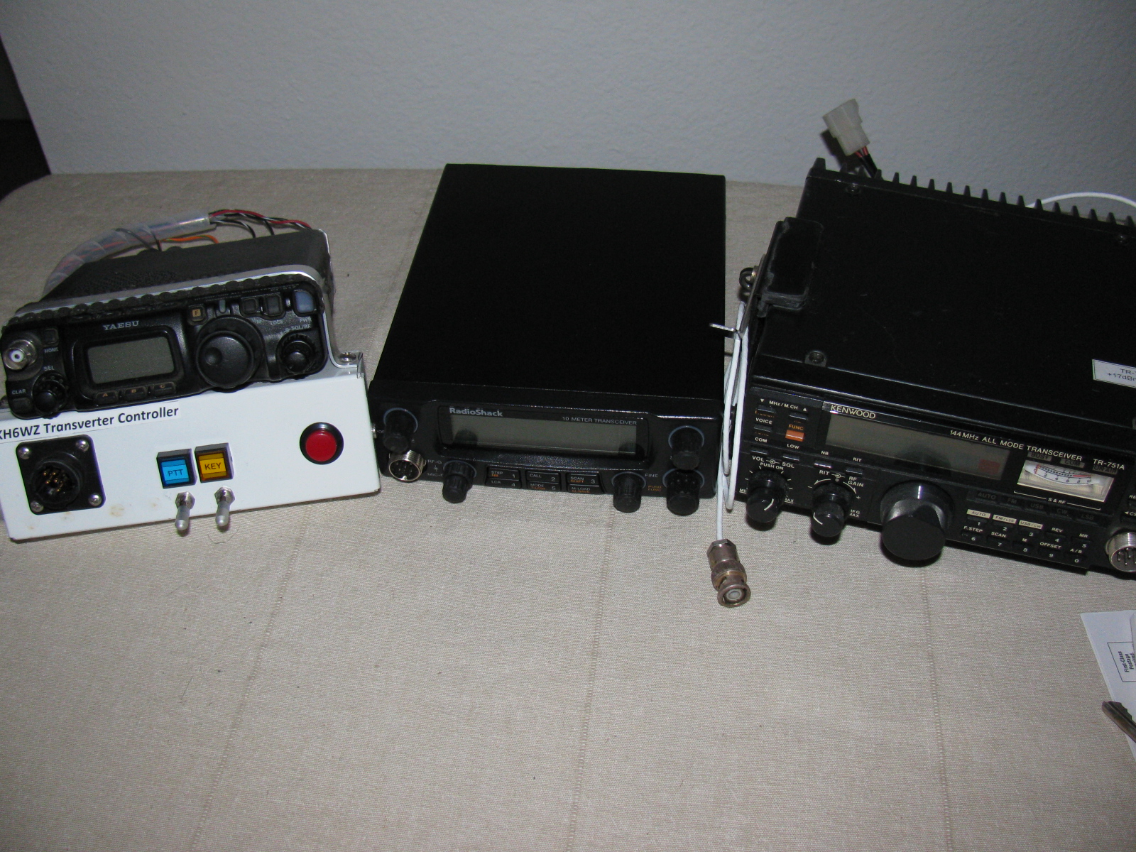
On most of my IF radios, I added a “convenience box” interface. This box converts all the interface connectors to ordinary RCA jacks. This is very handy in case my IF radio breaks: I can quickly swap any IF radio and swap it almost instantly, regardless of the IF radio model. My IF radios include a Kenwood TR-751, Yaesu FT-817, Radio Shack HTX-10, and some others.
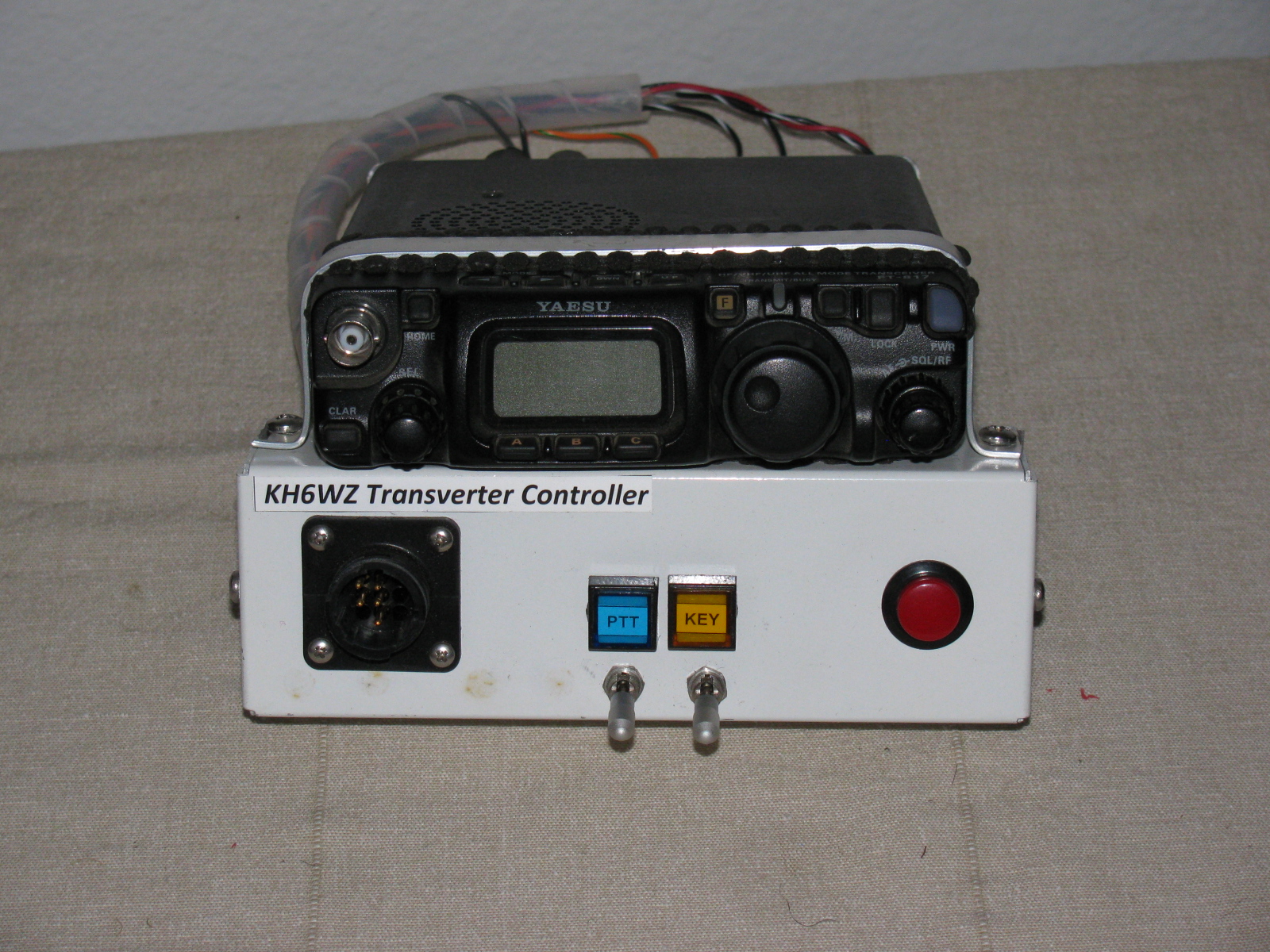
Here is a picture of the convenience box on my FT-817 . . .

KH6WZ IF Rig with RCA Jacks

IF Radio Convenience Box – Control
The white box front panel, from left to right: Multi-pin interface jack for DC power and control. Center left: Above, blue LED for “PTT Closed” indicator. The locking toggle switch is used to lock the IF rig into transmit (PTT Lock) mode to make it ready to send a carrier/beacon tone. Center right: Above, the yellow LED indicates “Key Condition.” The locking toggle switch is closed and locked to key the transmitter after the PTT is locked into transmit. The red push button is used to send CW in case I forget to pack my key or the key breaks in the field.
Essential for Success: Accurate Reference Frequency

To help ensure successful two-way operation on the microwave bands, a stable and accurate 10 MHz Reference oscillator is essential.
This can take the form of Ovenized Crystal Oscillators (OCXO), GPS-Disciplined Oscillators or Rubidium Oscillators. All of my transverters have OCXO units that I calibrate at a friend’s lab. Once set, I can depend on being very close to the displayed frequency. One secret: I keep the reference oscillator continuously powered throughout the contest weekend.
Although some club members have rigs using a rubidium or GPS standard, my OXCO-equipped rigs are able to match those other, more sophisticated radios without any problems.
Improvement Paths
Receive

Low Noise Amplifier (LNA) for 10 GHz
Low Noise Amplifiers (LNAs) can be found as Low Noise Block converters (LNBs) for Ku-band (12 GHz to 18 GHz) satellite TV receivers. Noise figures at or better than 1dB and 20dB-plus gain can be achieved. The modifications are easy and can be done without test equipment. Chip, N6CA published an example on his webpage.
Antennas

2-ft Dish vs 6-ft Dish
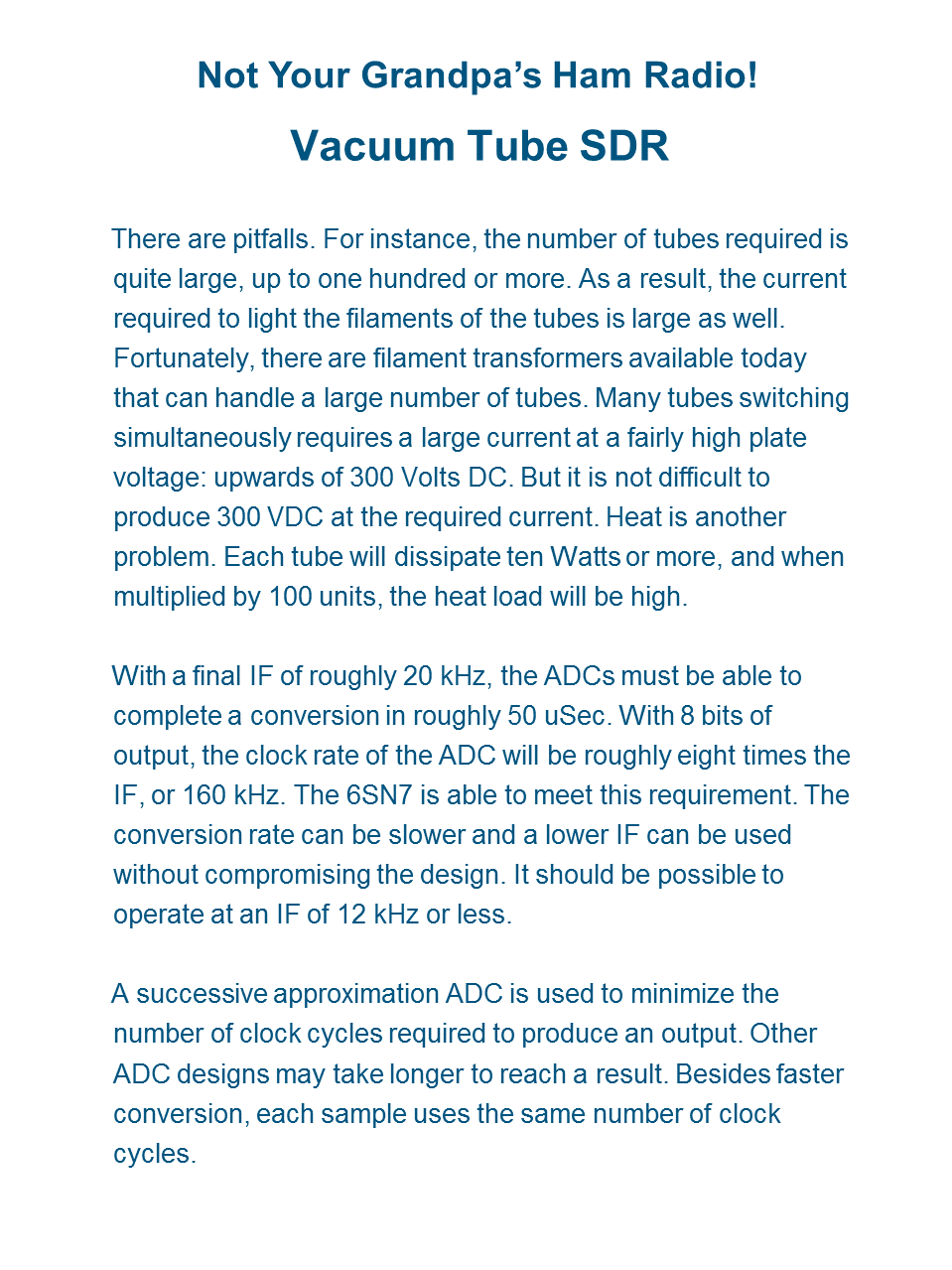
I call the picture above “Dish Envy.” On the left is Dick, WB6DNX with his 2-foot prime-focus dish. On the right is Robin, WA6CDR with his 6-ft dish.
Most beginning 10 GHz ops start with discarded and usually free satellite TV offset-fed dish antennas. But 24-in. diameter prime focus dish antennas or 24- to 30-in. offset feed antennas work better. Paul Wade, W1GHZ is an excellent online “microwave antenna handbook” – a great resource for hams.
Amplifiers – SSPA, TWTA

10 GHz SSPAs
It is amazing what one can find on eBay and other online auction sites.
High power amplifiers – Solid State Amplifiers (SSPA) and Traveling Wave Tube Amplifiers (TWTA) as well as other materiel for the microwave bands such as waveguide, SMA, Type-N and other connectors and assemblies are becoming available to just about anyone.
As mentioned briefly in the presentation, you must be careful when bidding or buying an amplifier for the 10 GHz ham bands, since some non-ham band amps may not be easy or may be impossible to convert to the 10 GHz ham allocation.
However, there are also many 10 GHz amplifiers that can be re-tuned (“snowflake tuning”) or used as-is. The term snow flaking is used when describing the tuning of microwave amplifiers or other surplus items. A step-by-step article about snow-flaking a surplus amplifier for 10 GHz is posted on the San Bernardino Microwave Society (SBMS) website. See “10 GHz Qualcomm Modification Notes” and “Modifying the Qualcomm 1W Ku-Band PA for use on 3.4, 5.7 or 10.3 GHz.”
When snow-flaking, a small wooden stick with a tiny speck of copper foil is touched and moved around the traces of an RF section while monitoring RF power. Watching for peaks, the small probe is removed, and a piece of copper foil is soldered in that location.
It is tedious but can be fun and rewarding when the job is completed and you have more power on the X-band.
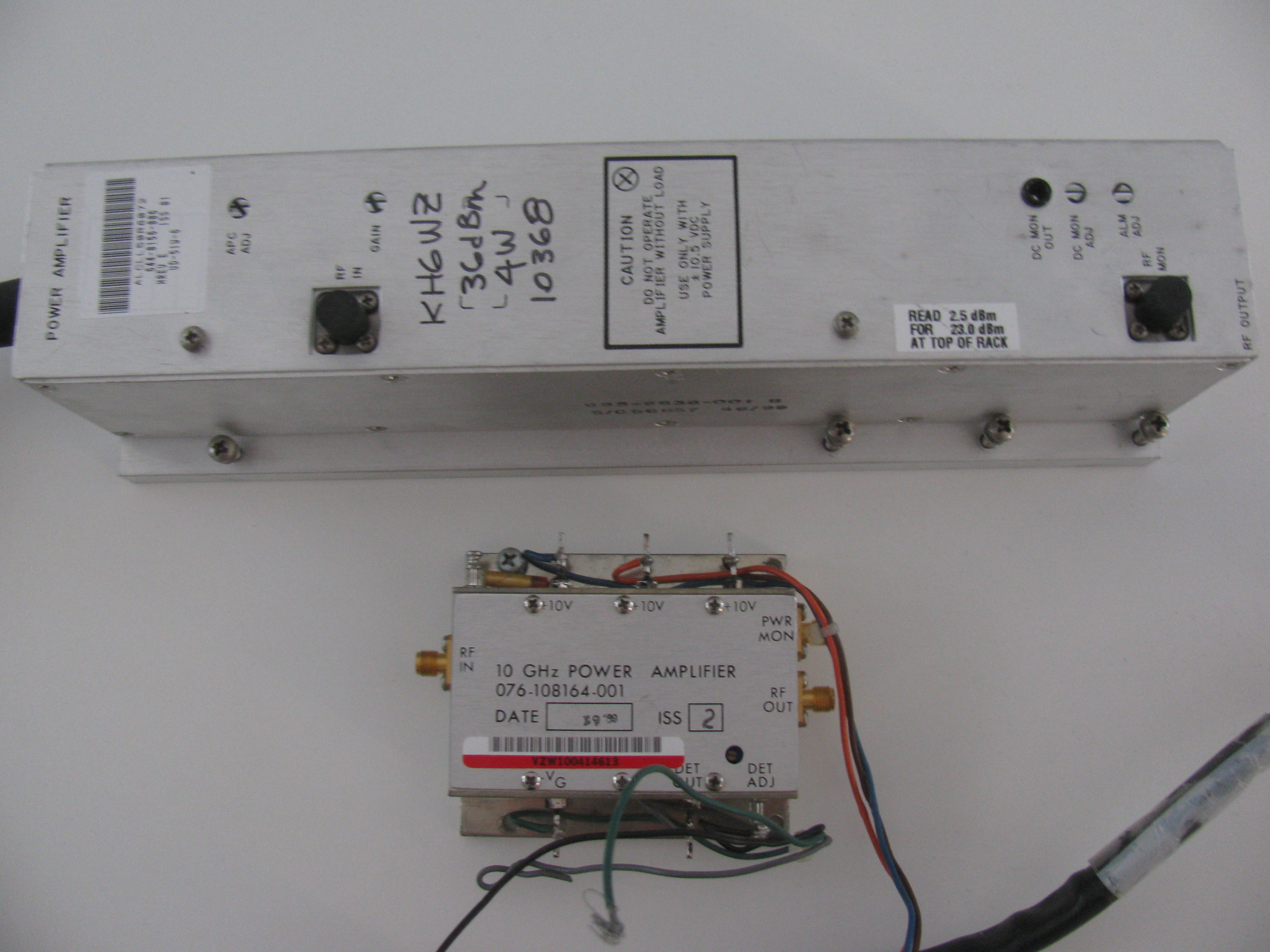
An excellent example of a small amplifier often found on eBay can be used without modification is the Harris-Farinon Model SD-108175 / 076-108687-001 solid state power amplifier (SSPA). I have several of these in use, and the power varies from about one watt to three watts on 10368 MHz.
See “Harris-Farinon 10 GHz Amplifier for Amateur Radio Use” in the References section below.
The good news is that many microwave ham bands over-lap the commercial or other non-ham service allocations (such as Wi-Fi, Bluetooth and Industrial, Scientific, Medical [ISM]), and amplifiers intended for these services can often be used as-is without modifications to the RF section. No tuning necessary.
In any case, all amplifiers will require a power supply (various voltages), power supply sequencing and high power transmit/receive changeover to integrate into a “beginner system.”
Sequencers: Protect Your Investment

Sequencer Demo at Maker Faire
When moving to higher than “driver power” (milliwatts), it is important to protect the receiver and amplifier circuits by delaying the time between receive and transmit. The delay needed is only a few milliseconds, enough time to allow the relay contacts to close and settle before the change from receive to transmit happens.
A sequencer automates switching various stages in this specific order:
- Antenna relay
- Transverter enable
- Power amplifier enable
- Transmit enable
The order is reversed when going from TX to RX.
In my Maker Faire display, pictured above, the W6PQL 4-Event Sequencer is used to drive a large Type-N relay (for T/R) and three high current power relays used to turn on the transverter support functions. It is available as a kit from the W6PQL website.
I have also built and use several sequencers based on Chip N6CA’s “Time Delay Generator” circuit, presented in many years of the ARRL Handbook (1997 and others).
I hope my presentation inspires more hams to try something different. There are many developments and new technologies to explore in ham radio, let’s continue the century-old Ham Radio Tradition in the 21st century style and remind people ham radio is still relevant today!
References and Resources
I am an SBMS member. Join us!
The San Bernardino Microwave Society (SBMS)
50 MHz and Up Group
North Texas Microwave Society
The World Above 1000MHz – Peter Day, G3PHO
USA Amateur Radio Frequency Allocations – The tiny bottom right corner of the chart
Microwave Update: The best technical conference to meet other active VHF-plus ops and learn more!
Technical Papers & Software from the San Diego Microwave Group – including modification information for Surplus Qualcomm boards made available to the ham community
10 GHz Qualcomm Modification Notes, by Dale Clement, AF1T – SBMS
Modifying the Qualcomm 1W Ku-Band PA for use on 3.4, 5.7 or 10.3 GHz by Kerry Banke N6IZW
“Harris-Farinon 10 GHz, 2W Amplifier for Amateur Radio Use” (Originally appeared in The Proceedings of Microwave Update 2005)
DUBUS – the serious magazine for VHF and up amateur radio
A List of VHF and Up Contest Locations in Southern California
Down East Microwave – Transverters and other kits and parts
Kuhne Electronic – Transverters and other kits and parts
Microwave Ham Radio Tom Williams WA1MBA
Jim Klitzing W6PQL – Sequencers, accessories, amplifiers and general information
Mike King KM0T – Great website with lots of pictures and construction notes
Wayne Yoshida KH6WZ – Various topics on ham radio, Maker Faire, and Factory Five Racing Type 65 Coupe
Read my LinkedIn profile article about ham radio and my career
Note: If you wish to connect with me, click the “Connect” button (not “Follow”) and enter a personalized connect request. I do not respond to the default connect requests.


Advice when soldering de KH6WZ
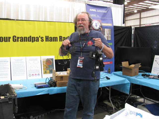
Not Your Grandpa’s Ham Radio 2016

Update
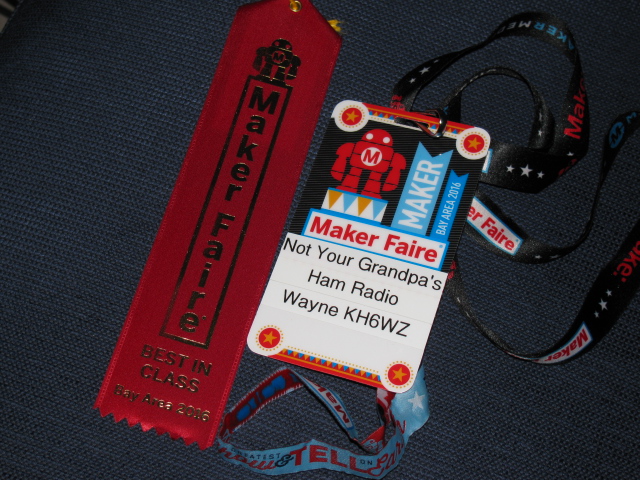
Not Your Grandpa’s Ham Radio Wins ‘Best in Class’ Ribbon
Maker Faire Bay Area was extra-special for us this year: We won a ribbon for “Best in Class.”
Maker Faire Hq. explains there are two ribbon categories: a blue ribbon for best in show, and a red ribbon for best in class. The red ribbons are also used to show the Maker has an educational element.
This red ribbon is an excellent victory, because the Maker Faire staff recognizes for our mission statement:
To show people what today’s ham radio operators are doing with the newest technology, and to change the image of ham radio, making it both contemporary and chic in a hi-tech way. We also want to emphasize how ham radio can be used for science and technology education and a possible career path for youngsters.
Our projects demonstrate how ham radio technology changes with the times, yet still includes both past and present to accomplish one thing: Creating ways to communicate voice and data over the ether, without wires.
Maker Faire Hq. keeps track of Makers as they (we) win ribbons.
Notice several Makers have multiple ribbons. Now we have an additional Maker Faire goal: We need to win a ribbon each year.
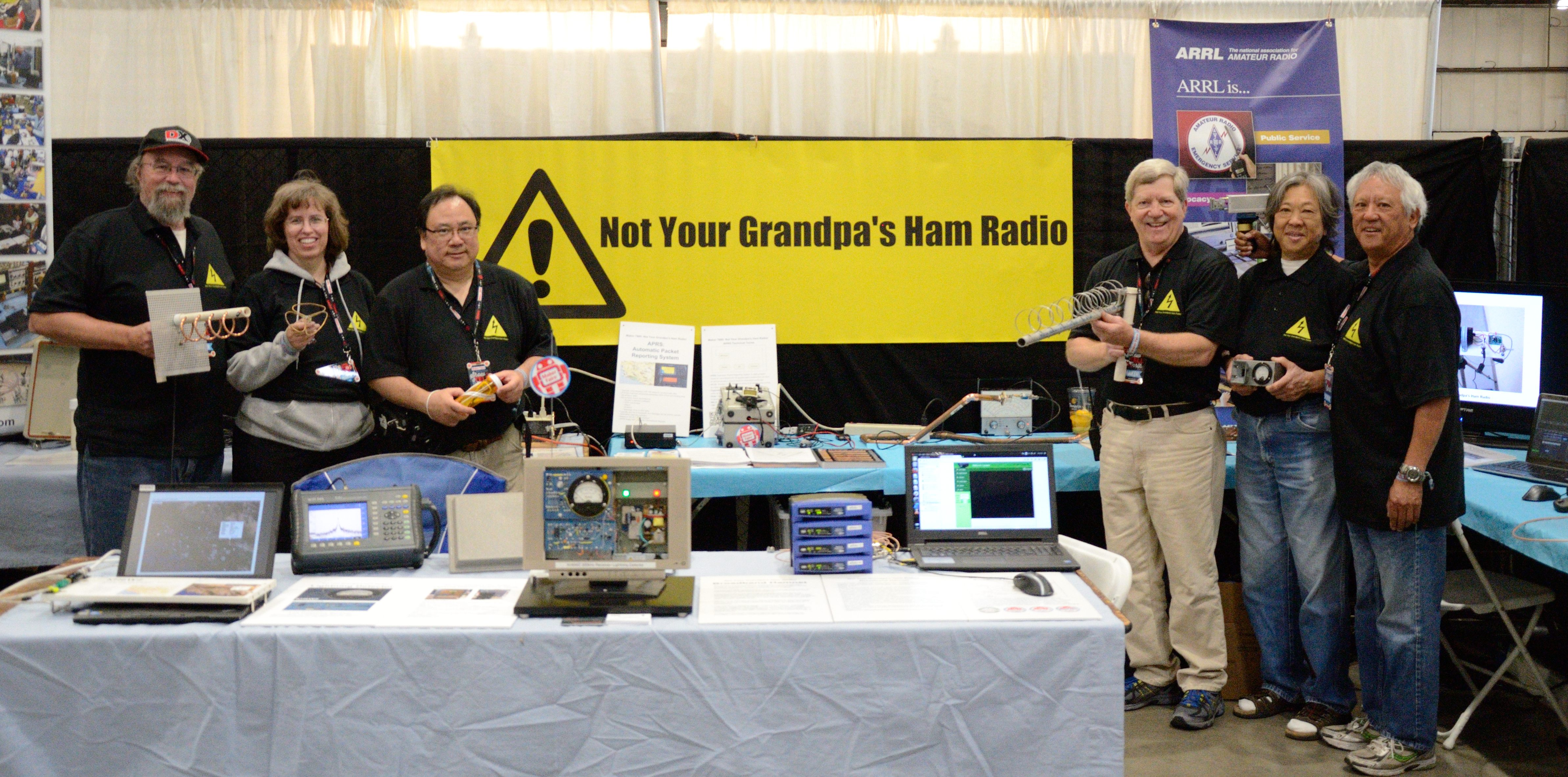
Maker Faire Bay Area Team 2016

Left to right: Dennis Kidder W6DQ, Lisa Gibbons KF6QNG, Wayne Yoshida KH6WZ, Marty Woll N6VI, Patricia Yee, Brian Yee W6BY. Not pictured: Joel Wilhite KD6W, Victor Frank K6FV and Paul Zander AA6PZ. The new polo shirts made by Dennis gave booth staff a professional look. Photo by Dennis Kidder.
A Setup Day Tradition and Treat – Gerard’s Paella

Hungry Makers ready for paella and various beverages after setting up their displays and activities.

Volunteers scoop and serve paella to the Makers after Maker Faire Bay Area setup day.

Gerard and his nephew Tom as the paella feast winds down.
This is a tradition at the Maker Faire Bay Area: Gerard’s Paella. Gerard Nebesky trucks in his crew and giant paella pans, which are about 20 feet in diameter. Gerard feeds over 2500 hungry Makers on Friday evening. A great big Thank You goes out to Gerard and his Maker Faire crew!
Here’s a quick video of the paella feast at the 2014 Bay Area Maker Faire.
New Projects
Lightning Detector, Low Frequency (300 kHz) Receiver

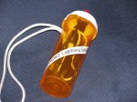
The completed lightning detector-300 kHz receiver completed a few nights before the Maker Faire. On the right is the “lightning simulator” – a piezo BBQ striker in a plastic pill bottle.
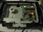
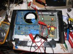
The lightning detector-300 kHz receiver is built into a broken LCD TV cabinet. Originally, I thought I could re-use the power supply, infrared remote control and audio amplifier. Unfortunately, the TV is built with a small number of ICs with multiple functions. The power supply performed strangely when I probed around to map out the output voltages. Since I was on a tight schedule, I gutted the unit, and kept only the speakers.
Lightning flashes and Tesla coils generate a wide range of radio frequencies near 300 kHz, slightly below the AM broadcast band (540 kHz to 1700 kHz). The electrical impulses can be perceived as “noise” or “static” in a radio receiver.
The Lightning Detector is a “resonant tank circuit” which detects the electrical impulses, amplifies them so the noise can be heard on a speaker, seen on the yellow LED and moves the needle on the meter.
A lightning simulator is used to test or demonstrate the unit in action when no storms are in the area. It is a low frequency, low level oscillator. Another way to simulate lightning is to use a piezo electric striker, like the ones used in some cigarette lighters and gas barbecue starters.
Information on this circuit comes from Charles Wenzel’s Technical Library (TechLib). There are a lot of interesting projects and includes a gallery of readers’ projects.


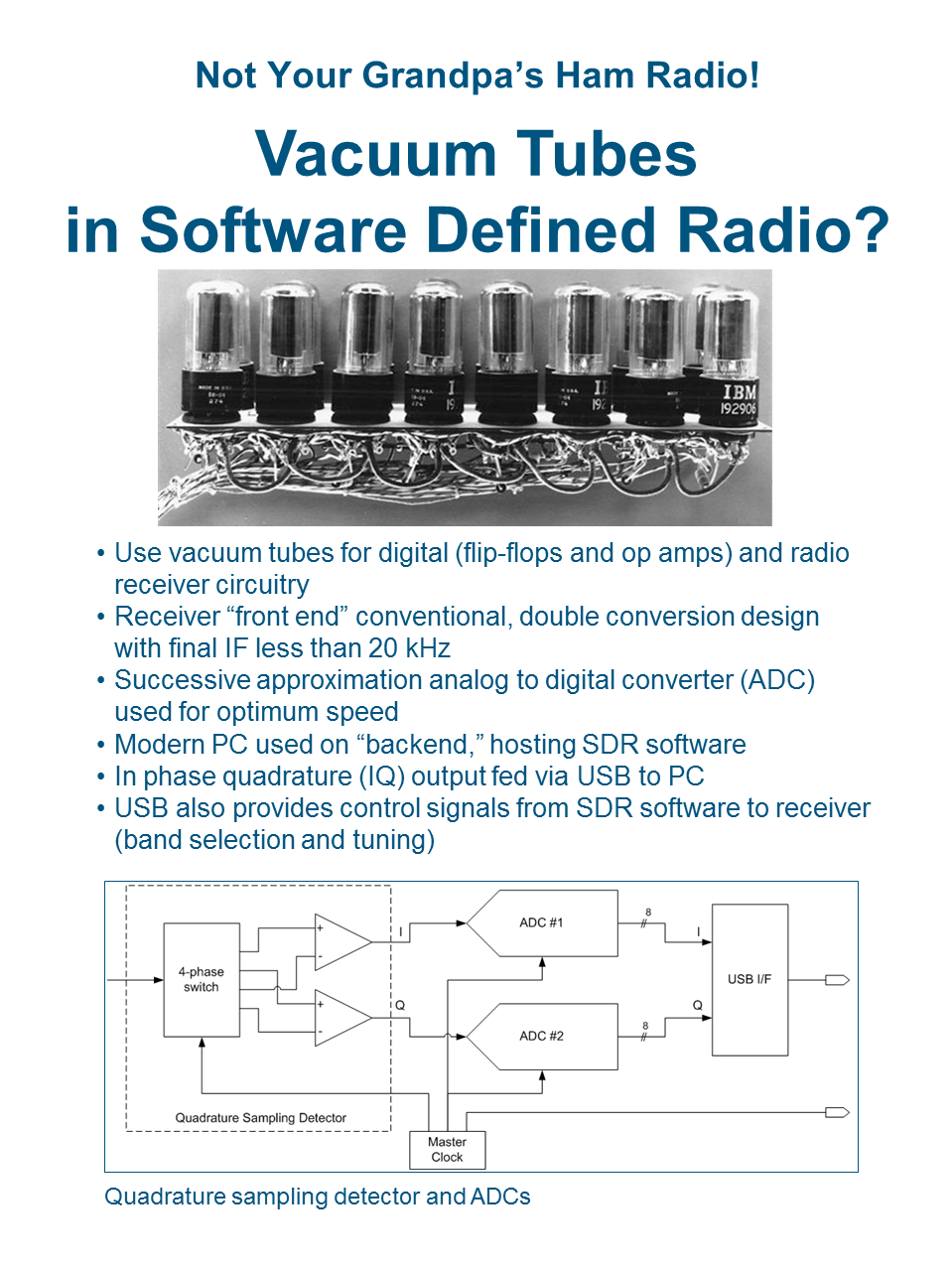
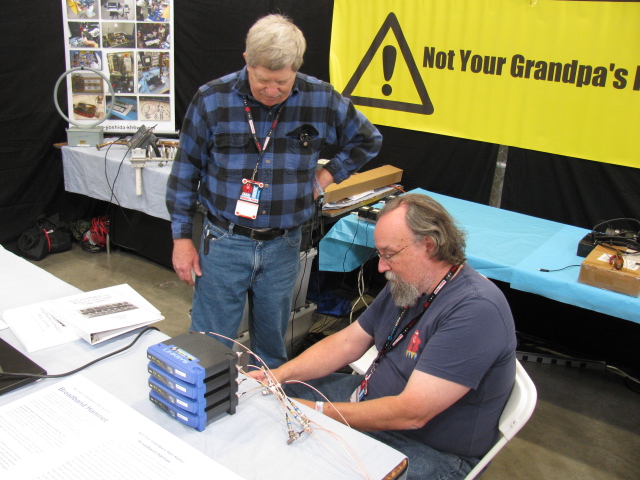
A Software Defined Radio – Made with Vacuum Tubes
A what made with what?
This is an interesting mix of old and new. Dennis Kidder, W6DQ, came up with this idea. Vacuum tubes are fully capable of performing many of the same functions as modern solid-state devices.
Dennis says, “The best part of using tubes in a project — they look really cool!”


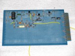
24 GHz Beacon

Brian Yee, W6BY, brought his Amateur radio beacon. A beacon is a one-way radio transmitters usually used as “propagation indicator” to help see how signals are traveling through the air. They can also be used as a signal source or reference to measure frequency, calibrate radio receivers and test antennas. Brian’s beacon operates on the 24 GHz band, and is made with modified microwave telecommunications sub-assemblies. An Arduino Nano is used as the beacon identifier. It sends out Brian’s ham radio callsign W6BY every 10 minutes (an FCC requirement) as well as a series of tones to help locate and identify the beacon.
N6VI Antenna and Spectrum Analyzer Demonstration

Marty Woll brought a portable spectrum analyzer and an assortment of hand-built antennas, including this corkscrew (circular polarized) antenna. A weak signal source was placed at the far end of the booth. By moving the antenna around, the spectrum analyzer shows frequency and signal strength. This can visually demonstrate antenna polarization and direction as well as frequency and harmonics.
KH6WZ 10 GHz Transmitter-Receiver System

The “anchor project” from past events is my 10 GHz transverter system. This station is used to demonstrate and explain frequency multiplication and division, frequency up-conversion (transmitting), down-conversion (receiving), polarization and antenna directivity to non-hams and even children.
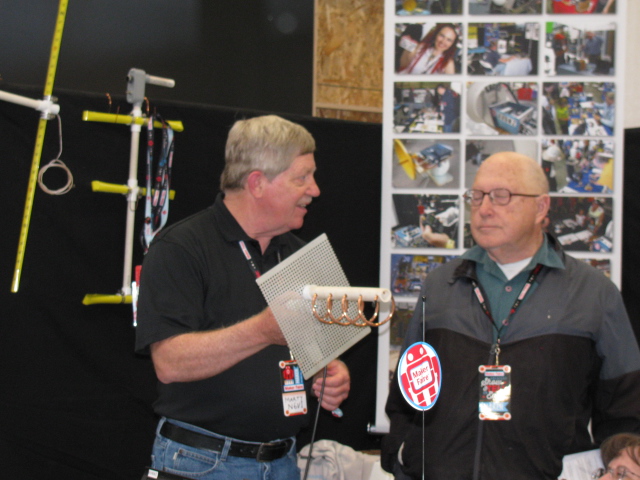
W6DQ Software Defined Radio (SDR) Demonstration

Dennis Kidder W6DQ, displayed his software defined radio (SDR). There were many questions about SDRs and many visitors were surprised to learn ham radio operators have this technology. But this is another example of what radio hams are using these days.
Virtual Air Traffic Control Receiving Station Using ADS-B – Automatic Dependent Surveillance – Broadcast

ADS-B is the “next generation” air traffic control, to replace/supplement ground-based radar. Each aircraft transmits identification, GPS position, flight information and other data.
It is very easy to make an ADS-B receiving station. Here are the things needed:
- A digital TV (DVB-T) dongle – DVB-T is Digital Video Broadcast – Terrestrial, a digital TV standard used in Europe and other, non-North American locations
- Antenna for 1090 MHz, this can be built with cable TV coaxial cable and a few other items.
- Windows PC
- ADSB# (ADSB Sharp), a free application
- Virtual Radar Server, another free application
- Browser and Internet Connection
An inexpensive (less than $20 US) digital TV software defined radio in a USB dongle is used to decode ADS-B signals. Free downloadable applications for Windows PCs are used to decode and display the live air traffic broadcasts on a computer.
There is one important thing to know when buying your DVB-T dongle: The decoder and display programs work only with dongles using the Realtek RTL2832U with the RaefaelMicro R820T Tuner chip set.
More ADS-B Receiver Information
“Virtual Radar from a Digital TV Dongle,” QST, January 2014
ADSB# (SDR Sharp) – Download
Virtual Radar Server – Download
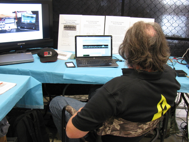
Broadband-Hamnet™ (formerly called HSMM-Mesh™) Demo

Dennis W6DQ (seated) assembling the BBHN network demo as Marty N6VI asks a few questions about the network.
Broadband Hamnet (BBHN) re-purposes commercial Wi-Fi equipment to operate only in the ham bands to create robust, wireless, IP-based networks suitable for emergency communications or remote monitoring and control.
Commercial Wi-Fi equipment is restricted through FCC Part 15 regulations, limiting power and range and precluding the user from modifying type-accepted products.
However, licensed ham radio operators are legally allowed to modify Part 15 devices to make them operate in the FCC Part 97 rules for ham radio operation. Larger antennas, higher power, adding receiver pre-amplifiers and other techniques are allowed for experimentation.
The result is a system which creates an ad-hoc, meshed network, supporting IP traffic, e.g., voice, video and data. A meshed wireless network affords greater reliability by providing alternative route paths in the event of a failure.

Dennis says there sure a lot of wires needed for wireless networking.
Note: There are two systems for amateur radio wireless networking – Broadband HamNet (BBHN) and Amateur Radio Emergency Data Network (AREDN). If you are interested in experimenting with this, check with others in your area to see what they are using.
10 GHz / 24 GHz Dual Transmitter-Receiver System

Joel Wilhite KD6W constructed a 10 GHz and 24 GHz dual-band transverter system for portable use. It consists of various modified modules from several sources.
We encourage kids and parents to talk to each other using our home-built radios. It helps make things more interesting than just looking at things.

APRS display of the KH6WZ-5 location beacon at the 2013 OC Mini Maker Faire at UCI. Notice the beacon message at the top of the screen capture includes the URL of the event – a great publicity tool!
This past weekend, the second OC Mini Maker Faire happened. And it just so happens to be the second running of my ham radio demonstration called, “Not Your Grandpa’s Ham Radio (2)!” This is my continuing mission to remind people of two things:
First, “The Maker Movement” is nothing new, Amateur Radio operators have been doing this for a almost a century, and nearly 2 million people worldwide are involved in ham radio in some way.
Second, Ham radio is not necessarily an old man’s hobby where weird guys talk to strangers from garages and basements. We are skilled wireless communicators and use today’s technology, from GPS and microprocessors to lasers and microwave frequency linking.
This time I added static and working displays of my various APRS beacons (KH6WZ, KH6WZ-5, and others). I programmed the OC Mini Maker Faire’s URL to the beacon message so people can take a look at what was happening – an excellent publicity tool!
I also planned on making some 10 GHz contacts with my rig, since this was also the same weekend as the ARRL 10 GHz and Up Contest. The transverter covers were removed so people can see the system’s guts.
Based on previous experience at the Discovery Science Center “Meet the Makers” event, I demonstrated radio wave polarization- horizontal vs vertical – with my rig and the microwave strength meter.
Since I had plenty of space, I shared my booth with a company that makes interesting computer and microprocessor related items. This may sound trivial, until you realize this company is run by these three young guys . . .
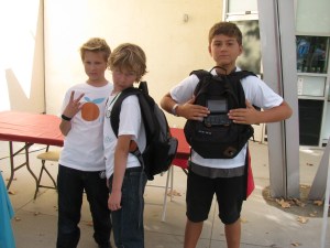
Huxley, Max and Ethan showing one of their products called the SmartPac.
There seemed to be more people at this Faire, probably since not too many other events were happening nearby. The 405/605/22 freeway closure did not affect the MF, since it started after the event ended.
More than a dozen hams – either active or at least licensed – stopped by to visit. We talked about this event as well as the Bay Area Maker Faire, and what ham radio activities we are involved with.
One more thing: I met several guys from the San Diego area – they are finalizing the plans to have a Mini Maker Faire in the San Diego area – this is great news. Stay tuned and I will announce an update as soon as I hear something from the committee!
Here are some pictures from the event. I am already thinking of building some new displays for next year.
-
-
The 24-inch M/A-COM dish with the KH6WZ logo makes a pretty decent sign for the booth, eh?
-

-
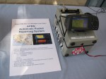
The KH6WZ 10 GHz transmitter-receiver unit on display at the Orange County Mini Maker Faire on the UCI campus
-

-
KH6WZ horn antenna and microwave field strength meter at the OC Mini Maker Faire 2013
-

-
The KH6WZ APRS beacon (unit 1) at the OC Mini Maker Faire 2013. This was a static display unit to show components and construction.
-
-
KH6WZ-5 APRS beacon – active and sending position data at the 2013 OC Mini Maker Faire at UCI. The beacon message included the Faire’s URL.
-

-
This familiar unit makes an appearance at the Maker Faire. . .
-

-
The robot “Titan” was a crowd pleaser – it throws flying discs and comes to you for a refill.
-

-
Track Roamer robot at the OC Mini Maker Faire. Notice the Nerf gun. When you come to next year’s event, remember to wear a red shirt.
-
-
One of the “roving displays” at the OC Mini Maker Faire 2013.
-
-
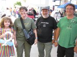
Some ham visitors at the Orange County Mini Maker Faire 2013: Haliey, Michelle W5NYV, Paul KB5MU and John KJ6HZ.
-

-
Michelle W5NYV wearing her daughter’s alpha wave ears. The ears move and react to pulses from a sensor clipped to her left ear.
-

-
An unknown couple wearing Vocademy shirts. What a great slogan: Eat, Sleep, Make.
I received some sad news today from EDN. Eric Lidow, one of the last true electronics pioneers – passed away on January 18. I worked for his company, International Rectifier, from 1998 to 2006, but used IR components in my electronic projects since I was a kid in elementary school. And when I was in the eighth grade, I won the Science Fair, Physical Science Category, with my “Photo Phone” – which used an International Rectifier solar cell in the receiver.
One day at the office, I received a plain envelope with just my name on it. Inside was a hand-written note from Mr. Lidow. He thanked me for “not presenting our products with too much hype.” I still have that note in my files, and will always remember his advice.
Visit the International Rectifier website, a lot of my content is still present in the archives. . .
International Rectifier
The EDN story