Archive for the ‘FFR’ Tag
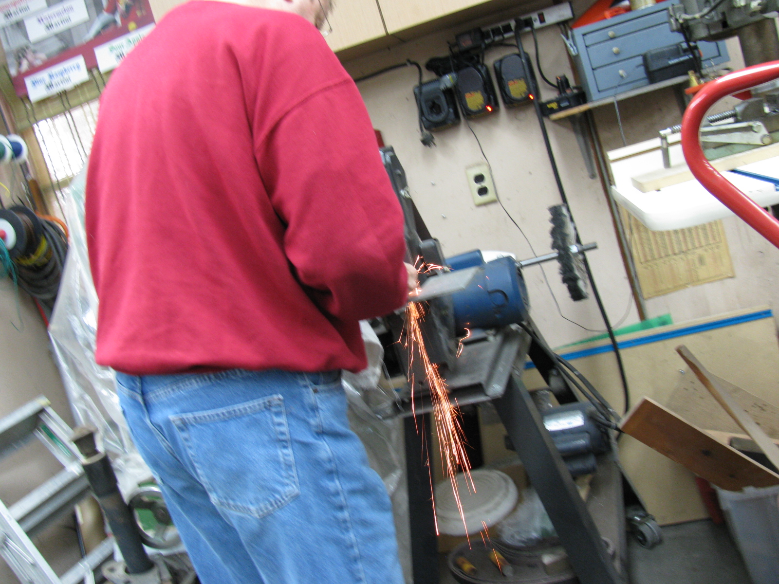
My go-to car builder friend Spider Larry once again came through for me. Using a Mapp gas torch and a piece of pipe, he separated the ball joint from the top mount for the passenger side suspension. Here are some pictures from the dis-assembly and re-assembly process on the Type 65 Coupe IFS, passenger side.


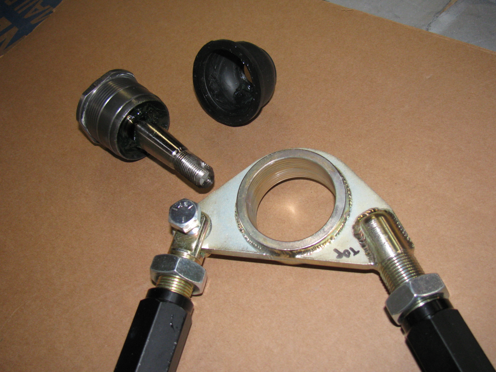
Here is the correct passenger side upper control arm and ball joint assembly:


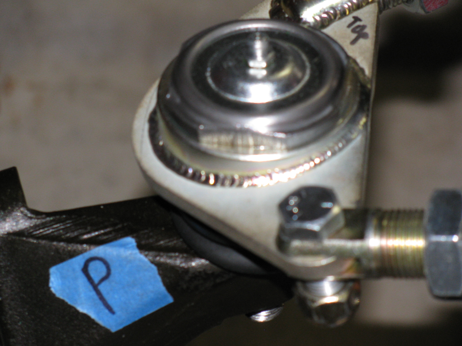
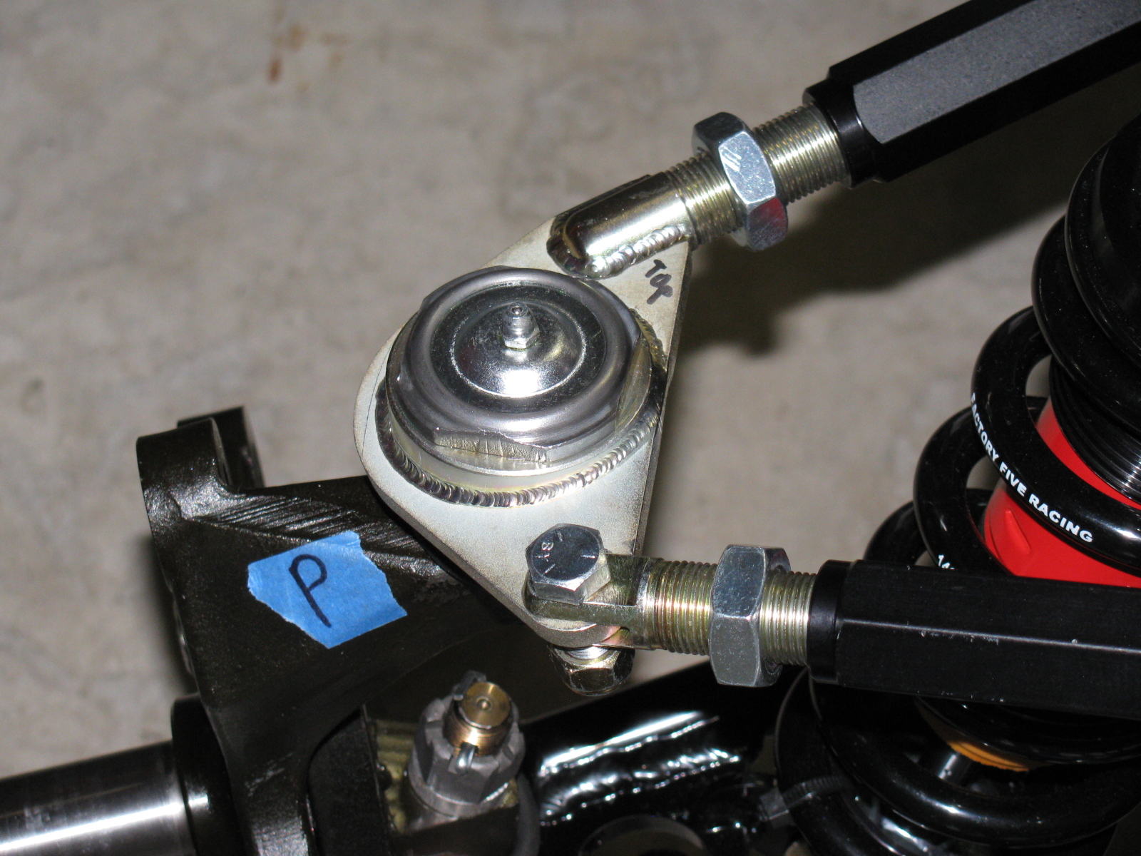
The driver side looks like this:


So you MUST ignore the manual when it says to create a “left and a right unit with the ‘solid corner’ pointing to the front of the car.”
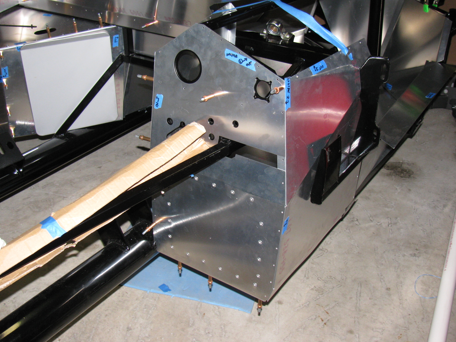
Footbox Heat Shields
I located, dry-fit, and drilled mounting holes for the driver and passenger footbox heatshields. The material is cookie sheet steel from the local grocery store. They have a nice rolled edge and will help deflect heat from the engine bay coming into the car interior. I am using riv-nuts and spacers to mount these sheets – er – heat shields to the footboxes.
I used BBQ paint for the shields, but may decide to powder coat the engine bay sheet metal parts, including the heat shields.
But I have to decide this quickly, since the engine is scheduled to be delivered within a few days!
Here’s the driver footbox with riv-nuts installed. All aluminum panels for the engine bay will be powder coated, the others will be painted.

Air Conditioning
Here is a picture of the air conditioner unit and where it will go. It fits behind the passenger side dashboard area, where a glovebox wold normally go. I need to allow space for the ducting and the windshield wiper mechanism, which mounts in the same area. A box to house the A/C unit will have to be fabricated.

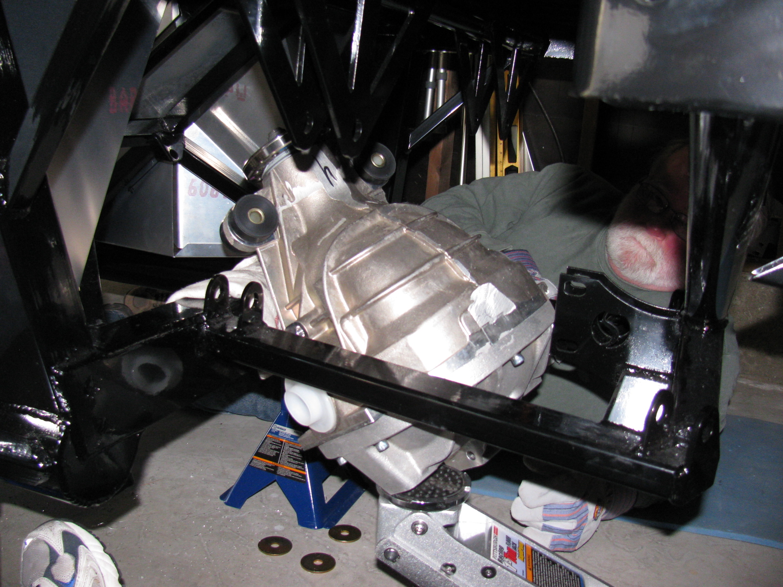
The IRS – Independent Rear Suspension
Note to builders: This procedure is quite difficult, even with a helper or two. It is highly recommended to keep small children away to protect them from hearing rated-R and -X words and phrases loudly coming from the underside of the chassis and to keep them safe from thrown objects.
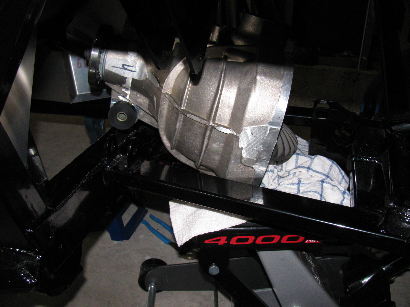
Since my ham radio friend Larry was going to stop by for a visit, I decided it would be a great time to get him to help me boost the rear differential (pumpkin) into the rear suspension cage. The Factory Five Racing assembly manual calls this unit the “IRS center section.”
There are many posts on how difficult this step is. The manual says, “It installs from the bottom with the driveshaft flange pointing straight up and the axle holes lined up front to back with the chassis.”
Err. So that means the giant 70 pound, lop-sided bowling ball like thing must be pushed up sideways, 90 degrees from the way it mounts onto the frame, and then must be twisted 90 degrees in the opposite direction to drop into place. This cannot be done safely with just one person. I found out that this is actually impossible to do with two people.
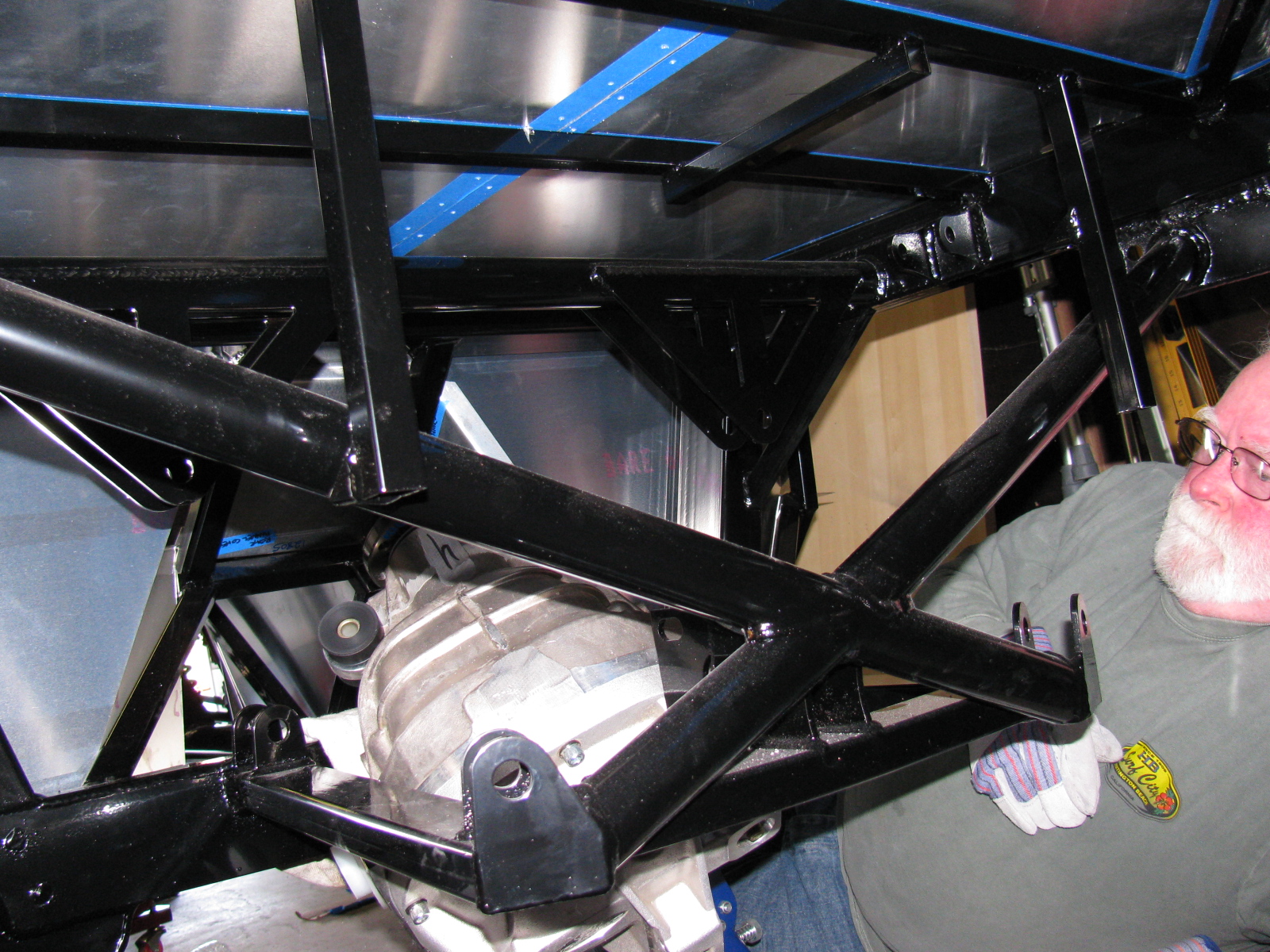
After several long hours and a phone call to Spider Larry, the pumpkin still refused to go into place.
I began to think about getting a grinder and removing any offending protrusions on the differential case and chassis to make this thing fit. My ham friend Larry had to leave, but a neighbor showed up, who also happened to be a car builder. I put Phil to work right away…
We tried a different route, maybe through the X-member at the rear of the chassis could work. So we used the jack to lift the differential high enough to check. We made a few measurements. No way.
We measured again, and noticed that no matter how you turn this pumpkin, it will not fit past the rear cover mounting plates.
We decided to remove the rear cover.
After unscrewing ten Allen bolts, and giving the rear cover a light tap with a rubber mallet, the cover popped off, very much like breaking an egg. To gain another inch of clearance, we removed the two plastic dust caps from the axle holes. Verifying that the diff does NOT have to come apart to mount the rear brakes, we put it back on the jack. Modifying the instructions, we lifted it with the driveshaft flange pointing up and the axle holes at a 45 degree (not 90 degree) angle, and pumped the jack. Now it went past the offending rear mounting plates, and into place.
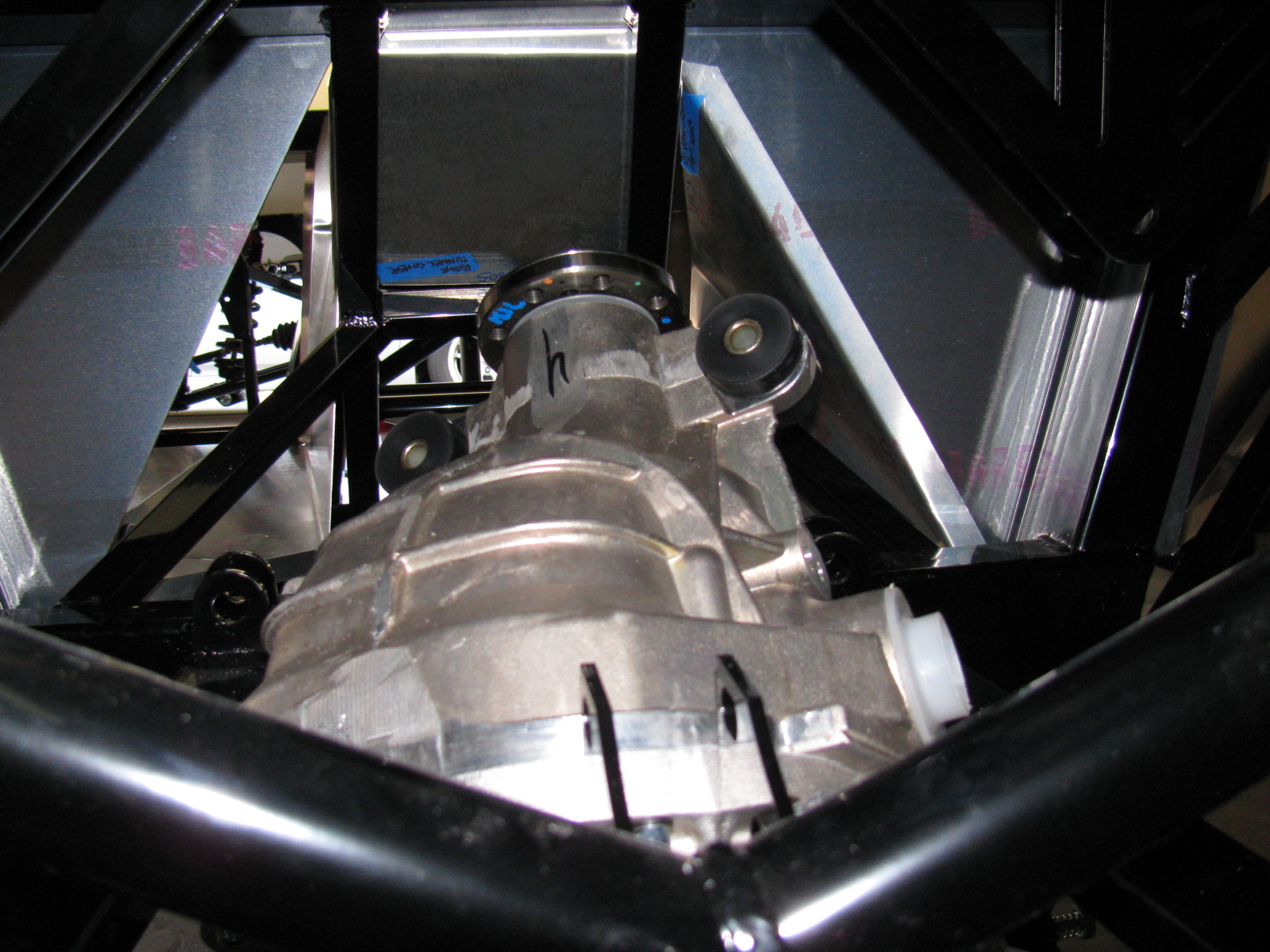
Of course, now the differential must be re-sealed, so we tried a dry run with the rear cover. Yes, this will work. I currently have the pumpkin suspended above the mounting location, held in place with the jack, a 2×4, and a nylon strap. I will finish mounting this beast at the next build session.
Here are lots of pictures of the wrong way to do this. A video of this procedure would be most helpful, but I am sure most builders will have enough in their hands to not have a camera operator getting in the way.


So – take my advice, save at least 6 hours and lots of non-child-approved words and thrown objects, and remove the differential rear cover before you install your IRS center section. . . .


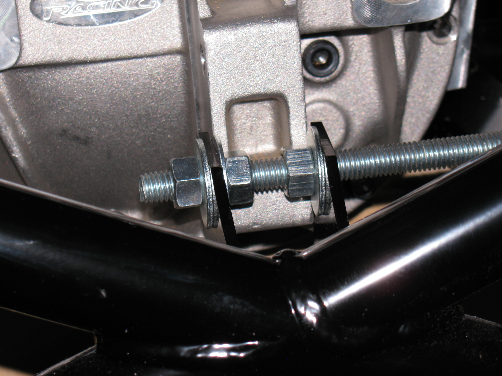
The rear mounting tabs (with the nice “5” logo laser-cut into them) are too close – use the threaded rod-expander trick to make it fit.
By the way – anyone else missing two nuts and bolts for the pumpkin mount? My parts list is correct, and yet I am still missing two fasteners for the standard width IRS differential.

I discovered I have the wrong adapter plates for the rear disc brakes, These are for the non-IRS version of the car. Jason at The Factory is sending the correct parts to me……

It’s been cold in the garage lately (50s-60s), but I wanted to get some more work done on the Coupe. My 302 is scheduled to arrive this month, but I have a lot of work to do before I can install the engine and transmission. This is one of those rare times when I can tell a supplier to take their time.
Back to this weekend’s update: What’s cookin’. When I lived in a small townhouse, I used to make a lot of meals in a Crock Pot, and noticed a few things: First, it was very handy to fill the thing up with various meats and vegetables, turn it on, go away for a few hours and dinner would be ready. Second, the smell was always wonderful. And third, it actually made the house a little warmer.
I decided this third effect of Crock Pot cooking deserved a try in my garage – and it worked. In the morning, I filled the Pot with my universal minestrone recipe and added some leftover spare ribs from the freezer. I call it “Spare Rib Minestrone.” The recipe appears at the end of this entry. It is roughly based on a minestrone recipe from Fat Free, Flavor Full: Dr. Gabe Mirkin’s Guide to Losing Weight & Living Longer. And it is pretty tasty. It made the garage a few degrees warmer, too. Here’s a picture. . .

Cooking in the garage – a tasty alternative garage heating method!
Halibrand-Style Wheels Arrived
The Factory Five Racing Halibrand-style wheels are BIG and beautiful. Wheels are 17 x 9 in front and 17 x 10.5 in the rear, and feature a spin-off hub. I am still not completely sure what tires will go on these rims, my preliminary choice is a set of Goodrich Sport-Comp 2 or something like that. This may change as I get a little farther along on my build.


The Steering Rack
I decided to see if I could finish the front end this weekend, especially since a lot of the back-ordered items arrived – I finally have a complete set of parts for my complete kit!
The steering rack is a non-powered unit made for the Mustang. Like many others, the mounting ears were too close together and I had to spread them out by a little over a quarter of an inch. I tried to use my pipe wrench trick, but the tabs are a little small and I wasn’t able to exert enough torque to move them. Doing some research on the Factory Five forums, I kept reading about people using a nut and bolt to spread mounting tabs wider. I finally found a post that included a picture of this, for future reference, it is located here, and I am posting photos and captions on my site as well so it may be easier to find. It’s a pretty neat trick, although no one says anything about the mounting tabs springing or bending back into their original position – you have to “over-bend” the tabs in order to make the part fit.
Here is my version of the mounting tab spreader tool using threaded rod, washers and nuts – I used 1/2-inch all-thread, since the 3/8-inch rod seemed a bit flimsy:

This really didn’t work too well, the tool needs another nut to hold it securely.

Like this

In the photo above, the open end wrench is being used to spread the mounting tabs outward. If the mounting tabs need to be smaller/tighter, move the washer and nut to the outside of the tab, and tighten the nut – squeezing the tabs closer together.
For the steering rack, I ran into another problem – that turned out to be a non-problem. As you can see here, after spreading the tabs out, the rack fits between the ears – but the holes on the passenger-side need to be moved about an eighth or a quarter of an inch to the left. After thinking about how long this will take using a rattail file, I took a break and thought about the steering rack. The driver’s side mounting tabs had a slot on one side – how come I am not able to move the rack over towards the driver side of the chassis?
The answer is, of course, yes, the slot is just enough to make the rack fit nicely. I used a punch and a mallet to move the rack into position. Success!

Compare the hole on the left (I used silver marker to show where to enlarge the hole) and the slot on the right. No reaming needed – I used a punch and a mallet to move the steering rack into place.
So now the tie rod ends have to be connected to the steering arms. But here is another problem – the driver side tie rod is too long – can I just get a hacksaw and cut off about an inch, as shown by the blue tape?

The driver side steering rack tie rod seems too long – but wait – something is amiss. ..
I decided to stop the steering rack installation at this point and get some answers before cutting the tie rod – because, as Norm Abram always said, “Measure twice, cut once.”
I came across the Summit Racing – Factory Five Racing Roadster build today – and there is a nice picture of the steering rack-tie rod connection posted here – this is for a Roadster, but I think the Coupe shares the same configuration. I have to give F5R a call to verify something – in the Roadster build, the steering tie rod to steering arms are upside down compared to my “dry fit” – Do the Coupe tie rods mount the same way? Also, the Summit Racing car has two lock nuts for each tie rod – my kit came with one lock nut for each side. The manual does not show the ends of the steering rack – poor photo-cropping.
Getting the Shaft
I did some test-fitting of the steering shaft – after some head-scratching moments, I figured out that I needed to remove the adapter that came with the lower end of the steering shaft, and replace it with another one, from another box of stuff. The length is just right, I have seen some early posts about the steering shaft being too long.
But I ran into another problem – the shaft does not come through the dashboard in the correct position. It is not as bad as some others I have seen, but still is quite a ways off. I am not sure if I can just cut the dashboard hole bigger to allow the shaft to come through, and patch the spaces or – what. More fiddling is needed.
Floor and Footbox Fitting – Passenger Side
I decided to do some more sheet aluminum work – this time, fitting the passenger side floor and footbox. Using the same technique as the trunk floor, I cut the passenger floor into three pieces. After the cutting, I noticed that I could have done this with only one cut, but the three pieces will be OK. I kept the left side un-cut, since it may be seen when the car is done. (I am not sure if I will apply paint or put carpet on the transmission tunnel area yet.)
At this point, everything is being held in place with Cleco pins. I want to test-fit, trim, drill and de-burr all the aluminum panels first, then apply paint – or powder coat them.
So although I think I did a lot of work on the Coupe this weekend, a lot of it does not seem to show. It still does not look like a car yet.

Cutting the passenger side floor.

Passenger side footbox – another jigsaw puzzle!
Something is Making Me Go – “Hmmmmmmm”
I noticed and wonder why the passenger-side side body mount area sheet aluminum is different from the driver-side side body mount area aluminum – take a look:

Driver side – side body mount near the footbox. . .

Passenger side – side body mount area, near the footbox – see the difference?
Here’s another look:

Driver’s side

Passenger’s side. . .
This is making me go, Hmmm. Or more like Arrrrrg.
Season’s Greetings
Somewhere during the weekend, I installed my Christmas lights. I decided to cut back this year, because of all the work I am doing on the car. My “Ho Controller” and box of new lights and other parts I bought last year will have to wait until next year. In the meantime, here is a shot of my display. One of my Universal Rules for events is: “Everything you setup must be taken down and put away.” So many people spend hours and days – or even longer – putting up such decorations. My setup: less than 10 minutes to deploy, and even faster to take down!

Before I forget – here is the Spare Rib Minestrone recipe:
Spare Rib Minestrone
Yield: 6 servings
1 Large onion, chopped
5 cloves garlic, smashed
2 celery stalks, diced
2 cups of chicken stock
1 28 oz can of crushed tomatoes
1 tsp oregano
1 tsp basil
1 can pinto beans
1tsp red pepper flakes
6 small red potatoes, diced
1 large zucchini squash
Some leftover spare ribs, with BBQ sauce
Put everything into the Crock Pot, with the leftover ribs on top, surrounded by the vegetables. Put the Pot on High for about 6 hours or until the vegetables are tender. Based on the Primo Minestrone recipe by Dr. Gabe Mirkin, MD in Fat Free, Flavor Full
The San Bernardino Microwave Society (SBMS) had a Christmas party this past weekend, and it was a good break from doing sheet aluminum work. The event seemed smaller this year, several of the usual suspects were not able to make it. There was lots of food to share and gifts to exchange. Happily, regular guests Mel WA6JBD and his better half, Tisza KI6DBR came and brought their usual homemade treats, including Tisza’s famous chocolate truffles, microwave dish cookies and a chocolate sculpture. This year’s sculpture was a 10GHz horn and a section of waveguide. And yes, they really do work at 10GHz. Mel measured the return loss of the horn and waveguide and reports more than 17dB or something like that – pretty respectable for an edible 10GHz antenna.
Here are some pictures of the event. . .

Where else but a ham radio Christmas party would one find a 10GHz horn and waveguide made of chocolate – that actually works

Tisza’s homemade chocolate truffles – Yum!


Gift exchange crowd
What in the World is That?
After the party wound down, I stayed to get a closer look at Dennis’ new camera. It does not look anything like a camera, but it really shouldn’t because it makes images in a whole new way and enables a whole new way to enjoy still images. I thought it looked more like a kid’s kaleidoscope, rather than a camera.
The camera and lens system optics look very simple. And that is one of the points: You do not need fancy telephoto or macro lens capability. It is done in software. There are no fancy controls or buttons, only soft pads on the rubberized parts of the case. There is a power switch, a zoom control and a shutter release. An LCD with touch screen is on the back. Here are some pictures of this new gadget.

WHAT is THAT!

The Lytro camera. At left is the lens cover, it attaches magnetically. That’s an item that will be lost immediately. Center, the camera, showing the front glass and lens. Right – a tripod adaptor.
As I mentioned on my LinkedIn update, the Lytro camera introduces a paradigm shift in the way we can look at still pictures (pun intended, sorry). At first, I thought this camera simply used some sort of image processing to “fix” images, simple things like contrast and color adjustments and maybe some image manipulation, like PhotoShop. But then Dennis said that you can change focus and “raw image” features, like zooming in – after the image is stored on your computer.
The images are not jpg or other familiar formats – but then – these are not ordinary images, either. You can actually change the depth-of-field – change the point of view of the image.
Watching some of the demos on the Lytros website made me think of scenes from the TV show “CSI:” because you can see an image captured by the camera, and you can actually zoom and move around the various places on the image, and see what else the camera captured.
Visit the Lytro website, pictures and demos and details are worth closer examination. Unfortunately, I don’t have any Lytro images to share – yet.
The Coupe Goof
The day after the party, I went back to work on the Coupe. Something bothered me as I looked at the images and some postings of other builders. The driver’s side footbox and the front, where the pedal box mounts, looked different than mine. And I found another driver side footbox front panel in my box of aluminum parts. I looked at the part number of the “extra” footbox front (15312) on the packing slip, and noticed the description: “Driver Footbox Front Wall, Coupe Wilwood Pedals.”
Argh. Since I have the Complete Kit, it came with a Wilwood pedal box. Part of the confusion is the way Factory Five Racing packed the sheet aluminum – the major parts are held in place on the chassis and are shipped in place. This would be fine for the builders using a donor Mustang pedal box, the “Basic Kit” version.
So, I had to remove the driver side footbox front panel and replace it with the proper one. The good news is that I had all these things in place with Cleco fasteners, not rivets and silicone. And, I used the old panel as a drilling guide for the new panel. Now I have a spare sheet of aluminum I can use for – something. Hatch covers, maybe.

On the left is the wrong driver side footbox front panel. This is the one that is shipped in place on the chassis. The one on the right is the front panel for the Wilwood pedal box. Good thing I didn’t silicone and rivet that panel!

Disaster averted – the wrong footbox front panel was removed and replaced with the correct front panel for the Wilwood pedal box.
I planned on doing more front end work this past weekend, including the installation of the steering rack, since I keep kicking that awkwardly long box on the garage floor. Then I wanted to move to the rear suspension, since the CV axles are finally on the way.
But as I thought about doing the work on the rear end, I decided to start drilling and fitting the rear trunk aluminum sheets. I wanted to avoid dropping aluminum and steel debris onto the new suspension and drivetrain components.
I want to drill and fit, not fasten and mount these panels, because they will be painted or powder coated later. This is always a messy and time-consuming task, and in the Coupe, a lot of the panels will be visible. Someone on one of the Factory Five forums said that if you count the number of holes you have to drill, you will lose the will to live. Funny. And true. Here are some pictures of the trunk aluminum.

Over all view of the Coupe trunk area. I used lots of Clecos on the back seam, because I had to pull the aluminum sheet on the rear panel tight against the floor.

The blue tape in this area is for a removable hatch to enable access for rear tail lights and the wiring harness. Better do that modification now, rather than later. Other access panels and storage boxes will be installed at various locations in the floor and the sides of the trunk.
I should draft a construction plan for this project, since I am almost randomly moving through the assembly manual.
My vintage-style Halibrand wheels still have not arrived, and I am missing some brake system fittings. When those parts arrive, I will have all the ingredients for the Factory Five Racing Type 65 Coupe Complete Kit. The engine and transmission should be done soon, delivery is sometime this month.
The front steering arms came in the day before Thanksgiving. That meant that I could continue building the front suspension. These little cast iron parts were the things holding my progress:

I installed the steering arms without too much drama. Installing the front hubs onto the spindles was another matter. The instruction manual says something about them being a tight fit, and that is true. I did not want to damage anything, so I used a PVC pipe elbow (remember the body dolly? This was a left-over part from that…) to protect the hub, and I used a plastic hammer to pound the hub into place. A few whacks and it slid right in. I hope that I won’t have to remove them someday – they are stuck on really tight.

And yes, a coupler or a T would have made a better anvil, but all I had on-hand was this elbow. Anyway – the hubs are now mounted to the spindles.

Torque spec for the hubs is 225 to 250 lbs/ft. This is a lot. The nut takes a 36mm socket and I bought one earlier (Coin Star money) just for this step. It took a lot of cranking on my 1/2-inch torque wrench to meet that 250 lb mark. I thought I was going to lift the chassis off the jack stands!
Thanksgiving Ribs
Meanwhile, I prepared some Kansas City Style pork spare ribs for Thanksgiving dinner at my sister’s house. I was in a hurry, and forgot to completely trim the ribs (the cartilaginous tips). I did, however, remember to remove the pleura – the silver skin on the back of the ribs.
If you don’t know about removing the skin from spare ribs, then I am sure you may have experienced eating that stuff somewhere. The pleura is the tough membrane that you might see on the back of the ribs. If left on, it blocks the spices and will never get soft after cooking – it is sort of like chewing gum, and ruins the eating experience….
Anyway, they were still very tasty, although I was out of paprika. No one else noticed it missing – but I sure did.

Ribs with a dry rub. I made two racks for Thanksgiving this year.

Smoky goodness.
After Thanksgiving Turkey
Per my tradition, the day after Thanksgiving, I went to the local grocery store and found a good deal on a fresh 12-lb turkey. I decided to try a recipe from Steven Raichlen’s Primal Grill TV show – see Orange Brined Turkey.
Strangely, both the book and the website say this is for turkey breasts. On the DVD, Steven smokes a whole 12-lb turkey. At any rate, I salivated over this since last year, and finally got to try it. Take a look at my version The bird is a hen, just over 12 pounds . . .

Orange brine for the turkey.

I need a bigger bucket or something for brining the turkey. I turned her (it’s a hen) over in the middle of the night.
Back to Work on the Coupe
Since the turkey had to soak over-night, I went back to the Coupe project. I started to assemble the front disc brakes, when another delay came along: No “supplied grease” for the disc brake slider pins. So I went onto the Factory Five forums and searched on what sort of special grease this might be. I almost skipped this step, but I am glad I did not. Lots of bad things can happen if the brake calipers stopped sliding on the slider pins.
Turns out the grease is special – the grease must be silicone-based, high temperature and must not affect rubber. So I did some more research and found this stuff: Permatex Ultra Disc Brake Caliper Lube Silicone Formula Item #24115. High temperature, silicone based and intended for brake caliper use.
There are some little spring clips that go into the brake housing, and some rubber boots that fit onto the caliper slider pins. The pictures are not too clear and I had to do some fiddling with the parts to make things look right. Here are some pictures that may help other builders. . .

This is the clip that goes into the long slot in the middle of the housing. If you are struggling to get it in, it is probably backwards. Hold it like this and insert it into the housing from the inside. It will just pop into place with a little bit of pressure.

The caliper slider pin boot is easier to install if you “un-curl” it first, like this.

Then you can push the little lip into the shallow groove in the pin. . .

. . . to make it look like this.
Since I was at the car parts store, I also bought a box of disposable gloves and some adhesive for the aluminum panels. There’s a ton of postings on what adhesive to use on the Factory Five Racing car projects. Many different adhesives are mentioned. But there was one build gallery that I found, and I am going to use the product they used – it is Permatex Ultra Black RTV silicone gasket maker, Item #24105. This is what Kirkham Motorsports uses in their projects, so I figure it would be acceptable in my Coupe build. Kirkham has an online assembly manual posted, it basically follows David Kirkham building one of his cars: Kirkham Motorsports Assembly Manual.
What Good is a Sale on Something When It’s Out of Stock?
Since I was running about getting the grease and other stuff, I decided to go tool shopping. A local hardware store chain had a 50 percent off sale on Makita and Milwaukee power tools this weekend – I thought this was the perfect time to go get that right angle drill I wanted. I got to the store, only to find no Makita or Milwaukee right angle drills available. I went to two stores and wasted half of my day looking for the thing. I decided to look for an alternative to the right angle drill – how about a right angle drive attachment? I did not find one of those, either. So I left the hardware store empty-handed – I think this was the first time that ever happened!
Back to the Turkey
After an overnight soak, the turkey is ready for the smoker.

Getting the Big Green Egg up to temperature (250 degrees F). Hickory chips were added.


I can never resist peeking. Orange brined turkey, after the first hour.

After the 2nd hour. I rubbed the turkey with butter and continued to smoke.

After 4 hours. Almost done.

Total time in the smoker: About 5 hours. Temperature in the thigh 170 degrees F. After a 15 minute rest, time to carve!


Yes, this is as tender and juicy as it looks. The mayo-mustard-triple sec dressing that is part of this recipe is very good. I think I will try this with lemons next time.
So not much work completed on the Coupe today, but the holiday weekend is not quite over. I hope to complete the front end tomorrow.
Having things from Factory Five on back order is not so bad. It just means that packages arrive every now and then, and it is sort of like having gifts to open and see. For example, earlier this week, the box containing the exhaust headers and rear view mirror finally came back to me. In addition, I received the rear brake kit and the rest of the rear end hardware and fasteners.
The headers are nicely polished aluminum and are surprisingly light for their size. It looks like they mount to the exhaust muffler assembly with these splice-connector sections. Other versions of this exhaust are joined with a flange arrangement. I am not sure if I like this method of connecting the headers to the muffler assembly. I will have to post a question on the Factory Five Forum to see what others have done.


The steering arms are still missing (FedEx tracking info indicates they are in transit and will arrive just before Thanksgiving – this is great timing, since I will have a few days off to do some more work on the car), so I cannot install the front disc brakes. The CV shafts are missing so although I can start on the rear end, I will have to stop in the middle and wait for those pieces before I complete the rear end assembly.
So, I decided to work on the aluminum panels this weekend. I marked, center-punched and drilled the driver’s side footbox first. I used my new cleco pins and pliers for this sheet metal project. I really like them – I wish we used these in Mr. Spence’s 7th grade metal shop class!


See the gap at the peak of the box? I will install a strip of thin bar stock over the entire top seam to make it look better.
Some of you are wondering – what’s a cleco? I wondered about that, too. Wikipedia says, “A cleko, also spelled cleco, is a fastener developed by the Cleveland Pneumatic Tool Company. . .”
http://en.wikipedia.org/wiki/Cleko
So the next thing you may be wondering is – why do I have to use temporary fasteners to put these sections together? Another good question. I have to trim, drill and assemble all of the sheet aluminum parts – and then take everything apart so I can de-burr the holes, remove all the marks and scuff the panels to get them ready for paint. Although some builders have left these panels un-coated and raw, I decided to apply a finish to all the panels to prevent corrosion. My plan is to paint all interior panels (except the dashboard) with silver Rust-Oleum high temperature barbecue paint. I will paint the dashboard with Gray Hammertone – a darker color than silver, and it will have a nice contrast against my AutoMeter gauges.
Everyone seems to talk about the high temperature part of this paint, but no one mentions the fact that no primer is needed. I think that is one of the best features of this paint – one less step to do.
An alternative to the BBQ paint is what I use for my electronic chassis project boxes – Rust-Oleum Appliance Epoxy. This is another paint that does not require a primer, and the stuff is pretty durable. I would use that instead, but the colors are limited to white, black and almond. Yuk. Too bad.
At least, that is the plan so far. I might change. I am also considering some color alternatives to my original plan of having a white body and black stripes. But that part is a long way off. I will make a final color selection when the Halibrand wheels arrive – they still have not shown up yet.
It looks like there are just three things missing from the kit: The front steering arms, the rear CV shafts and the Halibrand wheels. The 302 V8 and T5z transmission should be here in December – so some serious building is about to begin!
My “new guy BBQ” happened on schedule. I met a handful of the local builders and had a great time talking about the kit and getting some advice from the guys who built their cars. Mikey and Mike and Larry and Julie and Julie and Frank and JJ and some others are now new friends. Even with name tags, I still can’t remember everyone’s name – and I didn’t take enough pictures – so this means another gathering will have to happen again soon!
The guys helped me remove the rear body shell from the chassis. (Actually, they did most of the work.) This was an important step, because now I can start building the car.
I marked and removed all the chassis aluminum panels. Some panels were stuck or wedged solidly in place against the frame without any fasteners. The trunk floor is going to be very difficult to put back in – I had to pull, bend and twist the sheet to get it out of the car. While doing this, I made some pretty deep scratches in the side panels and the chassis. I think cutting the trunk floor in half lengthwise will make it easier to put into place. We’ll see.
Here are some pictures from the gathering….

While some people slept, I started roasting a pair of tri-tip roasts on the Big Green Egg. . .

The BGE was still at cooking temperature, so I added some sausages . .. .

Awesome red Factory Five Racing Roadster

33 Hot Rod by Erik – it is low and black and mean!

Beautiful custom head rest!

Look very carefully at the switches on this dashboard

Coupe as received

Thanks to the guys visiting today, the body shell was removed – a significant step – since the project begins with un-building all of the sheet aluminum panels from the chassis.
Remember Jim Carrey as a package delivery man in the movie “Pet Detective”? He must have delivered these two boxes to my house earlier this week.

These boxes look pretty bashed. Notice the bulges? Heavy stuff rattling around inside.
Inside lumpy box one is the differential, with no packing materials in it. The “pumpkin” weighs 69 pounds. It was rolling around inside the box, trying to break out. Lumpy box two contained the rear spindles, 25 pounds.

Differential for the Coupe Independent Rear Suspension. What’s missing? Packing material. There’s 69 lbs of cast metal and lots of gears just rolling around inside a single-ply cardboard box.

Lumpy box number 2 contained the rear spindles.
Amazingly – nothing seems to be damaged. While these items are very robust, I wonder if shipments like this got damaged or lost while in transit – the box containing the spindles had many holes in it – the threaded studs were pounding against the box.
These parts are part of the “drop ship” items for the Coupe build, so Factory Five Racing did not pack the parts this way – their supplier did. I sent a message to the F5R guys as a heads-up, so hopefully this will get corrected.
Halibrand wheels, rear brakes, engine headers, body scoops, radiator bottom mounting piece, CV rear axles and some other stuff have not arrived, but I have enough parts to start building!
My friend Dennis took these photos of the big delivery on October 9, 2012.
This was a tough delivery for Bob from Stewart Transport, since the delivery day was set right in the middle of a street re-surfacing week. The shipment had to be dragged on the dolly from the end of the street to my house, since the Stewart trailer is 70 feet-plus long, and could not make the right angle turn to my driveway.
Make a note of this and if you are not sure, verify with the Stewart Transport people about what is required (turning radius) to get to your house. I have had large cranes on my street (when a new air conditioning unit was installed at my house), but I think the crane may have been very wide, and not really long.
Another thing to consider is how much room you have to store all the boxes you will get. I received 24 large boxes – enough to fill one side of my two-car garage.
It took me two full days to take inventory of what I received, and I still need to check the “chassis-mounted parts.” Some items are on back-order, and I hope to see them soon.
Here are some pictures of the Big Day, taken by Dennis. The other images of the kit and parts were taken by me.

The famous Stewart Transport trailer with the built-in crane unloads a fresh Factory Five Racing Type 65 Coupe.

The Type 65 Coupe on the dolly at the end of my street.

Bob from Stewart Transport and the first dolly-load of boxes.
Taking Inventory. . .

I used a stack of not yet emptied boxes as my desk while taking inventory. Twenty-four boxes total.

I selected the Auto Meter gauge package from Factory Five Racing for my Coupe.

Beautiful wiring harness kit from Ron Francis Wiring.

I always wondered what that warning sticker said on all the Factory Five Racing hoods.

At the end of the second day, both the Coupe and Prius are in the garage.
The Building Phase begins – soon. Stay tuned!
This afternoon, Bob from Stewart Transport called – the big day finally arrives – Delivery is set for Tuesday afternoon.
Two pairs of jack stands and a floor jack are needed to move the shipment into the shop – check. All ready for the delivery!
I am not going to post any “before” pictures of the garage.

I wonder if I will be able to fit the Coupe and the Prius in the garage