Archive for the ‘Factory Five Racing’ Tag
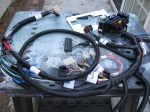
I should have done more homework on this part of the build process, since Factory Five Racing tells us they do not include the fuel system. This makes sense since it will depend on the engine. I have a 302 with an MSD Atomic EFI system, and it came with the (external) fuel pump and filters.
So now I have to figure out how to get from the fuel tank output tube to the first fuel filter, then to the pump and then to the EFI unit. I decided to install a return fuel line, based on the information in the MSD instructions, I hope this extra effort will be worth it.
I will make access holes and hatches for the fuel pump and filter, as well the rear suspension components and tali lights – this should make maintenance and repair easier.
Here are some pictures of the work done today.

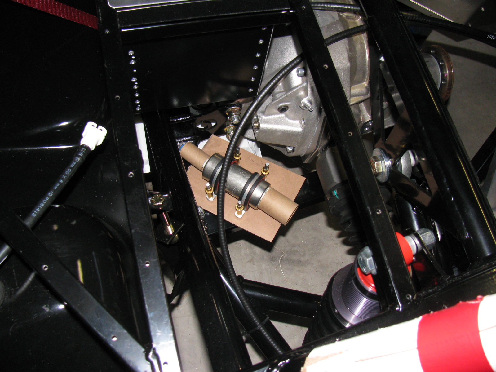
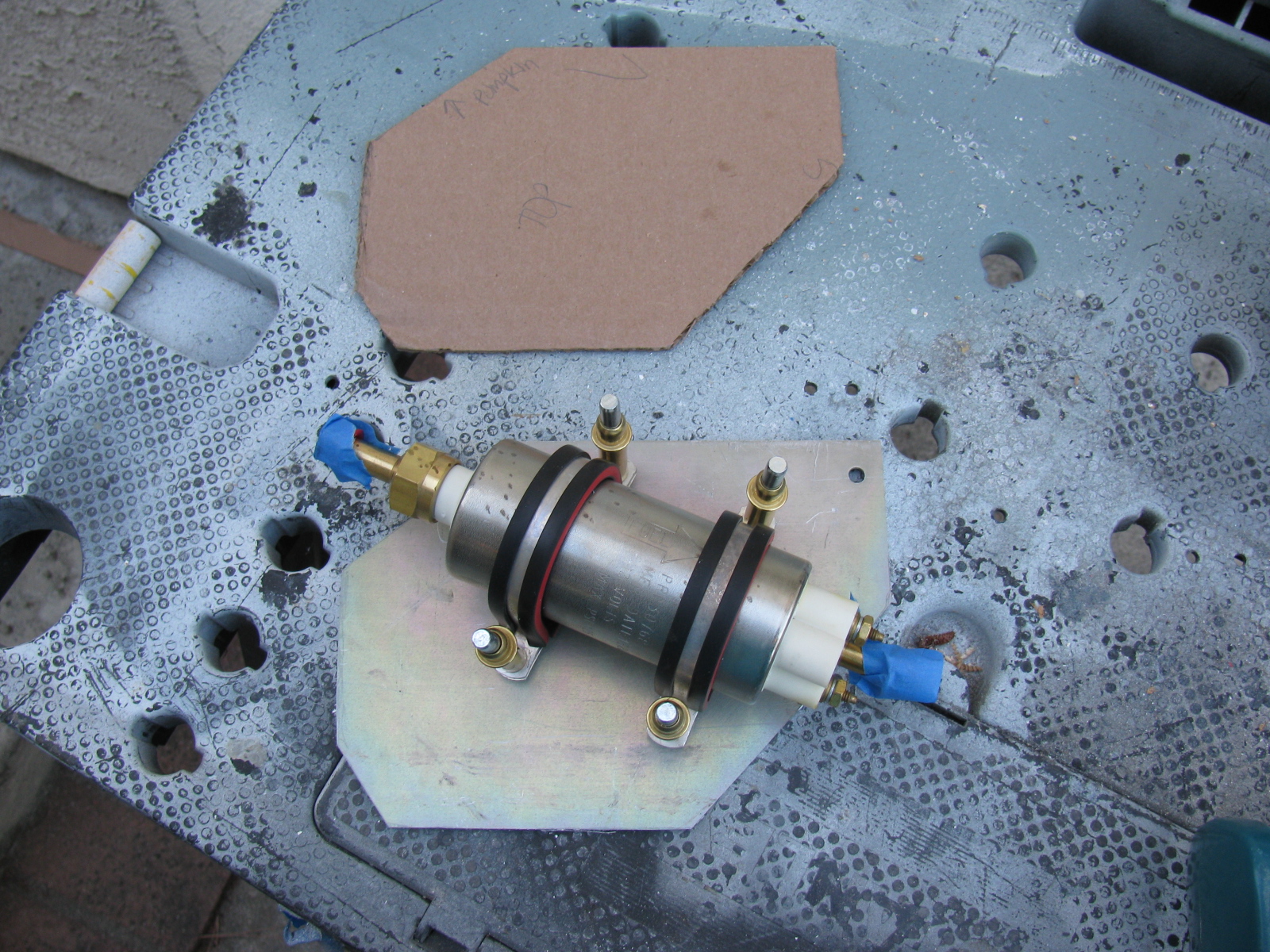
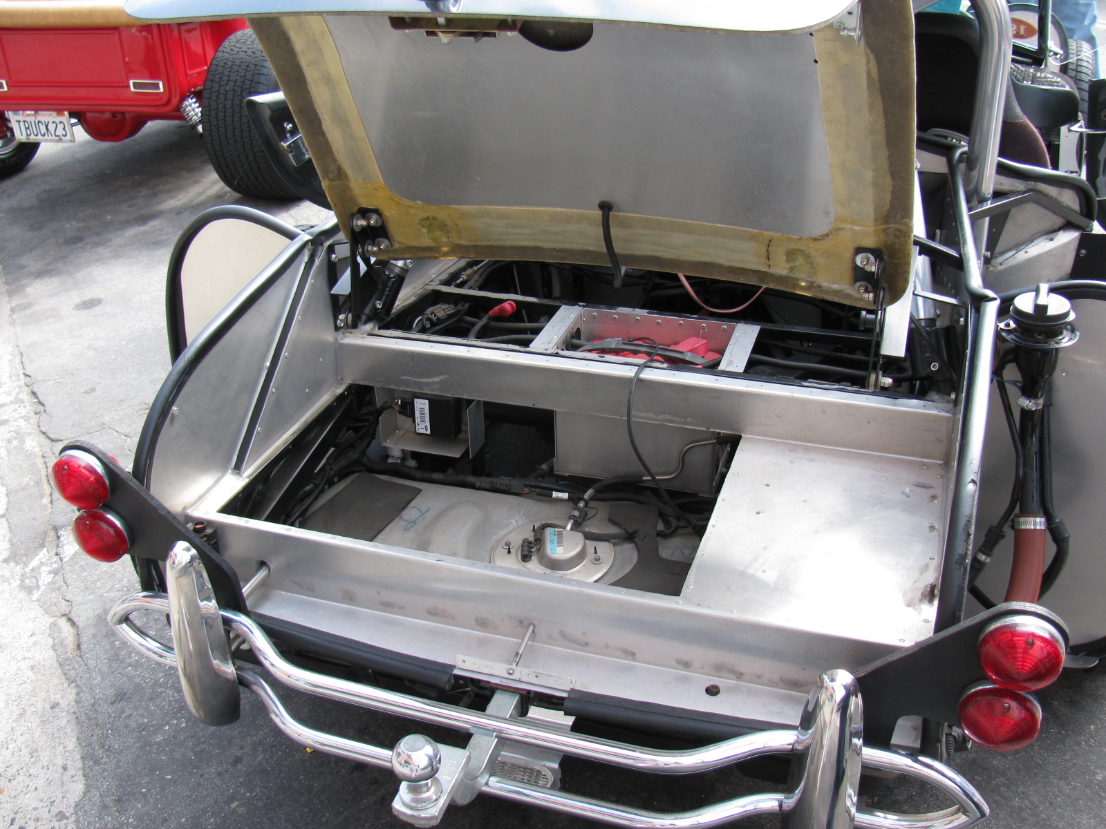
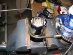
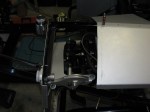
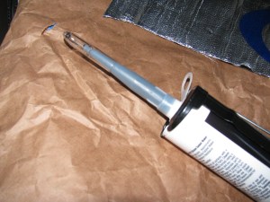
Type 65 Coupe fuel pump possible location. This is the external pump that came with the MSD Atomic EFI kit. The first fuel filter will mount to the battery box.

Using CAD – cardboard aided design, the fuel pump mounting plate is taking shape.

Here is the fuel pump in its possible location.

The cardboard template is transferred to aluminum. The mounting plate is almost a quarter-inch thick, so it will be nice and sturdy. This piece will be drilled and painted later.
By the way – the fuel tank is still not in its final location – the right side mounting bolts are not long enough. I may just get a length of all-thread and make my own bolt for that side. The left side seems to be OK. Next on the “To Do” list is fill and bleed the brake system.
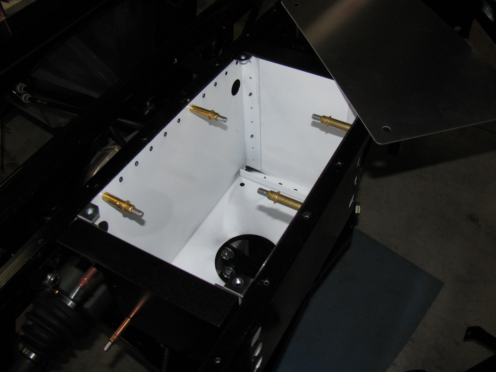
I painted and installed the slightly modified battery box from FFMetal this past weekend. Just to be different, I decided to paint the box white on the inside and black on the outside.
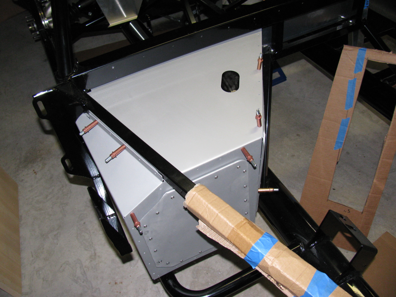
As you recall from my previous Coupe update, the battery box fits very tightly into the chassis – and I figured out a way to install the battery box without scratching up the paint – the trick is to install and build the box piece-by-piece into the chassis space. In other words, do not assemble the battery box and then mount it into the chassis – instead, build the box into the chassis.
NOTE: By building the battery box into the chassis, adjusting one side of the box inward (as described in my previous battery box notes) may not be necessary. Try a dry-fit before you drill the side of the box to change the dimension slightly.
This is actually easy to do, but difficult to explain. Here are some pictures of the freshly-painted battery box installation:

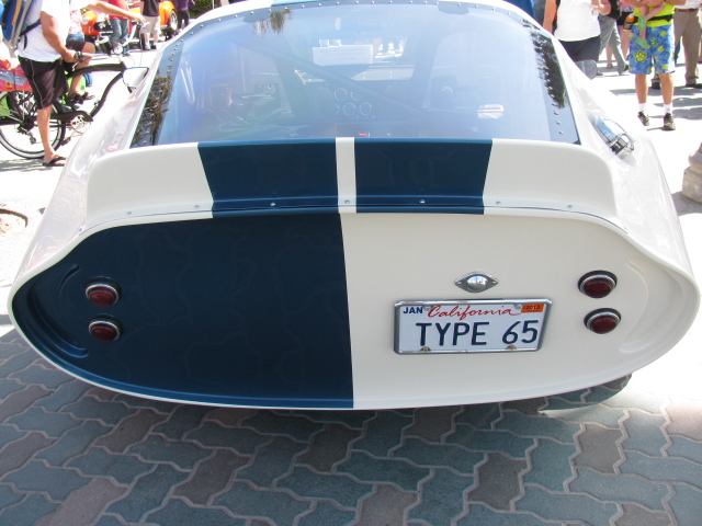
FFMetal battery box for the Type 65 Coupe – the individual parts are inserted into the frame one piece at a time, Cleco-ed into place, and then riveted. (Left side view.)

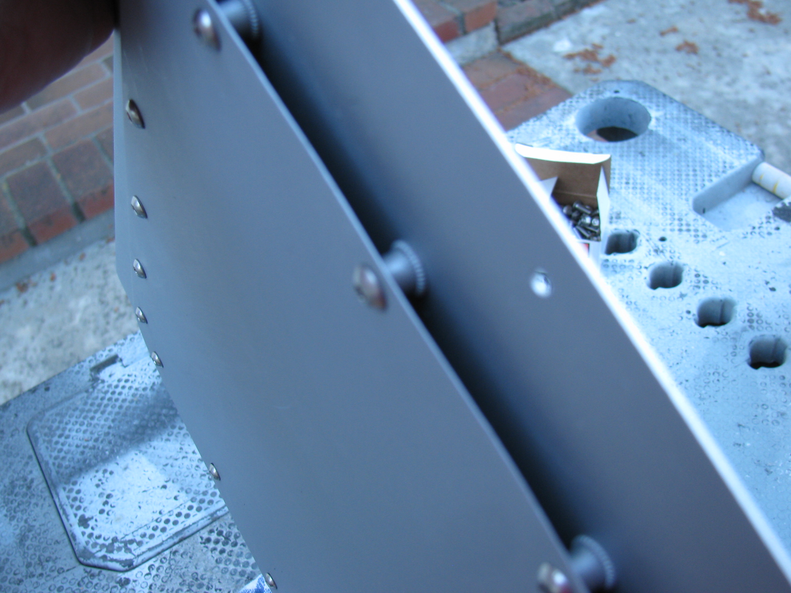
A close-up of the small cut needed on the left side of the battery box. This cut-out does not interfere with the battery – but the battery clamp bar may have to be moved, depending on where terminals, vents or filler caps are on the battery.

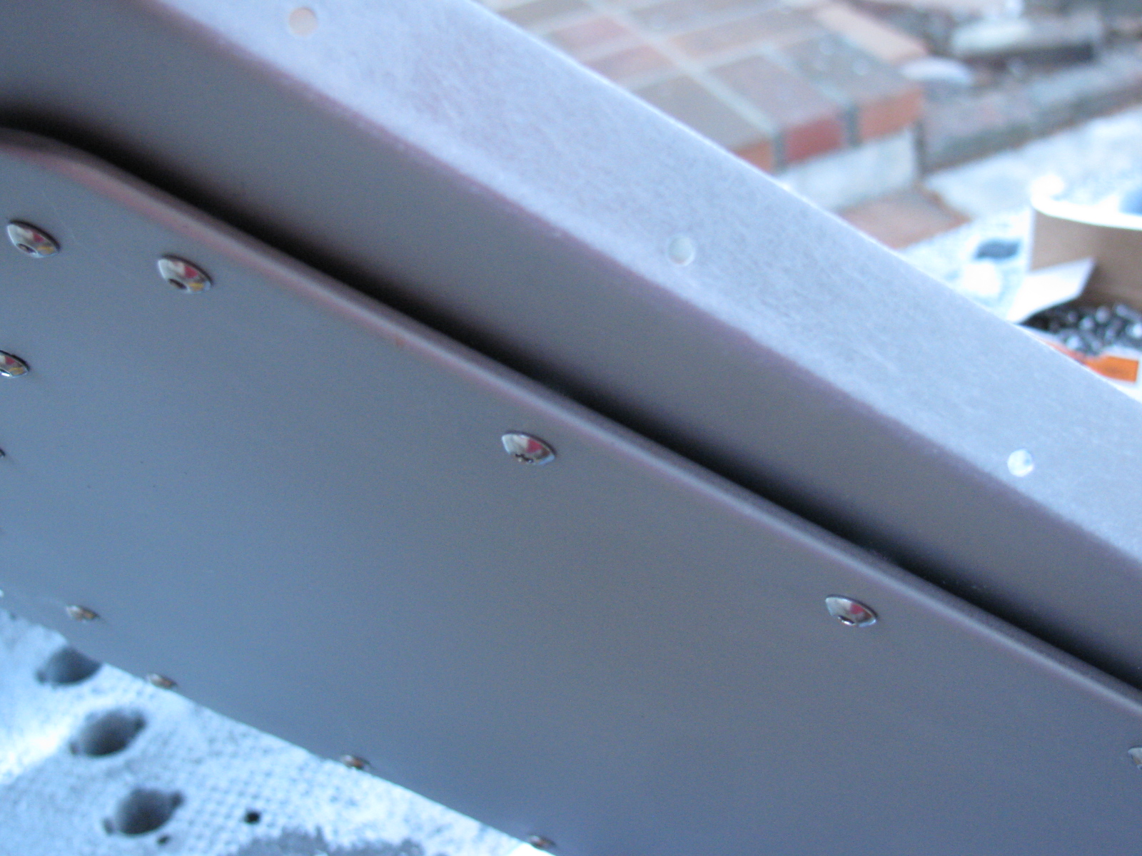
Another view of the two-tone battery box. I like the white interior, it makes it look nice and clean. Of course, a lid will cover everything later. . .

Another view. . .

The battery box with the supplied cover in place. Since I moved one side inwards, one cover screw does not line up properly. This does not bother me too much – I will install a small piano hinge at the upper side of the battery box, and the bottom two screws will hold the cover in place.
When the trunk floor panels are installed, I will make a cut-out to access the battery compartment. The instruction sheet shows how to make the cut-out in the floor panel, but I will make the cut-out with an easier technique that woodworkers use: A router and pattern bit. I will show how this is done when I get to that stage.
I may make a small finger-hole on the cover so it will be easier to open. Insulation and carpet will cover the entire trunk area later.
It’s been a long time since I posted an update on the Factory Five Racing Coupe. Here is an update in pictures and captions . . .
-
-
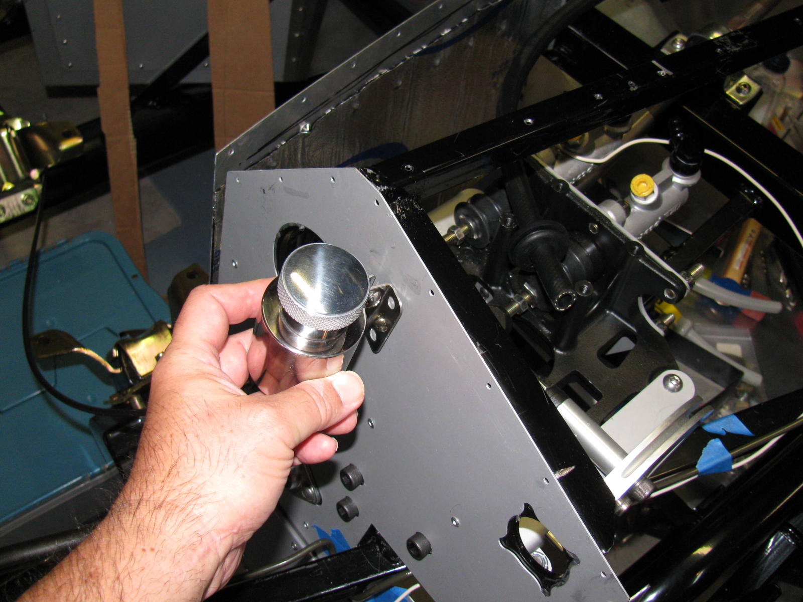
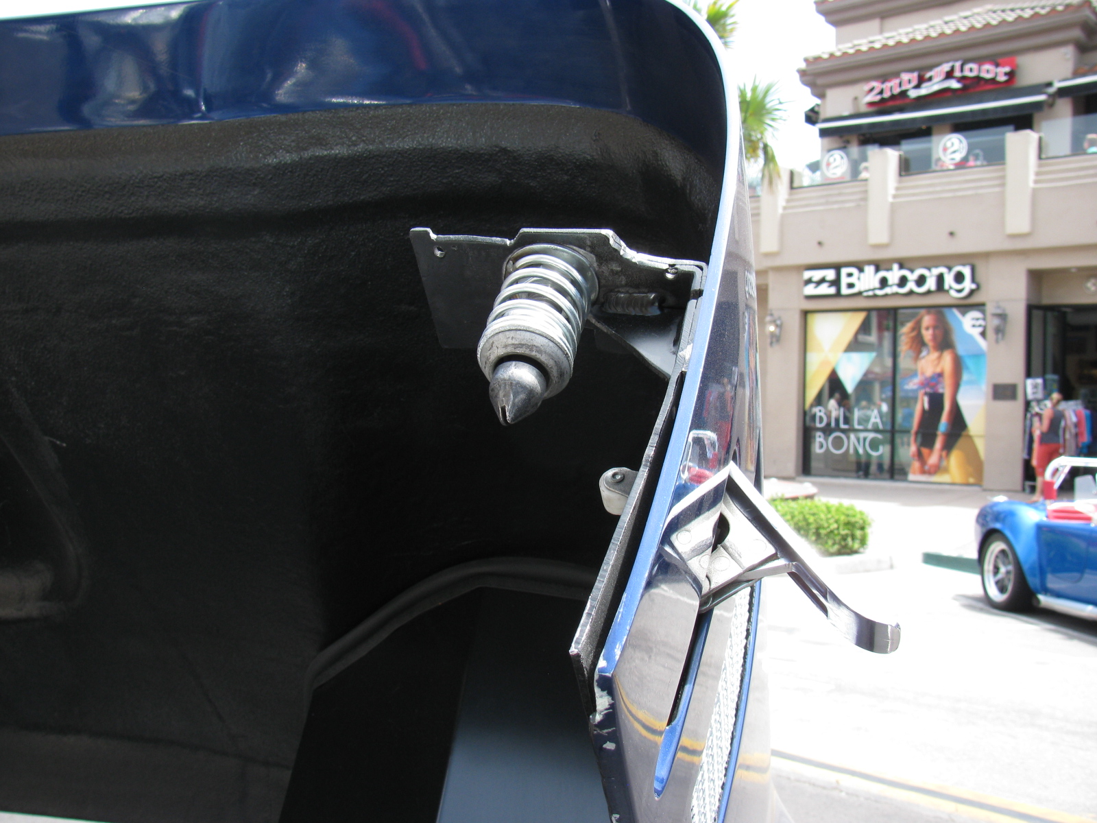
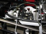
Type 65 Coupe complete kit brake reservoir bracket location
-
-
Polished stainless steel brake reservoir can, Type 65 Coupe, Complete Kit
-

-
I added a plastic grommet from the hardware store electrical section to prevent chafing the brake fluid hose.
-
-
I followed the hose layout as shown in the current Roadster build manual.
-
-
I used a big socket (35mm, I think) in a bench vise to bend my brake lines. Nothing fancy.
-

-
Brake lines are bent into rough shape, then taped in place along its route. Final bending is done on the chassis by hand.
-

-
Brake line held in place with tape, More adjustments are done by hand. Notice the way the excess lines are curved – this allows flexing in two planes – up and down and left and right. This is a 40-inch, pre-flared line I bought at a local car parts store. The supplied 60-inch line was way too long.
-

-
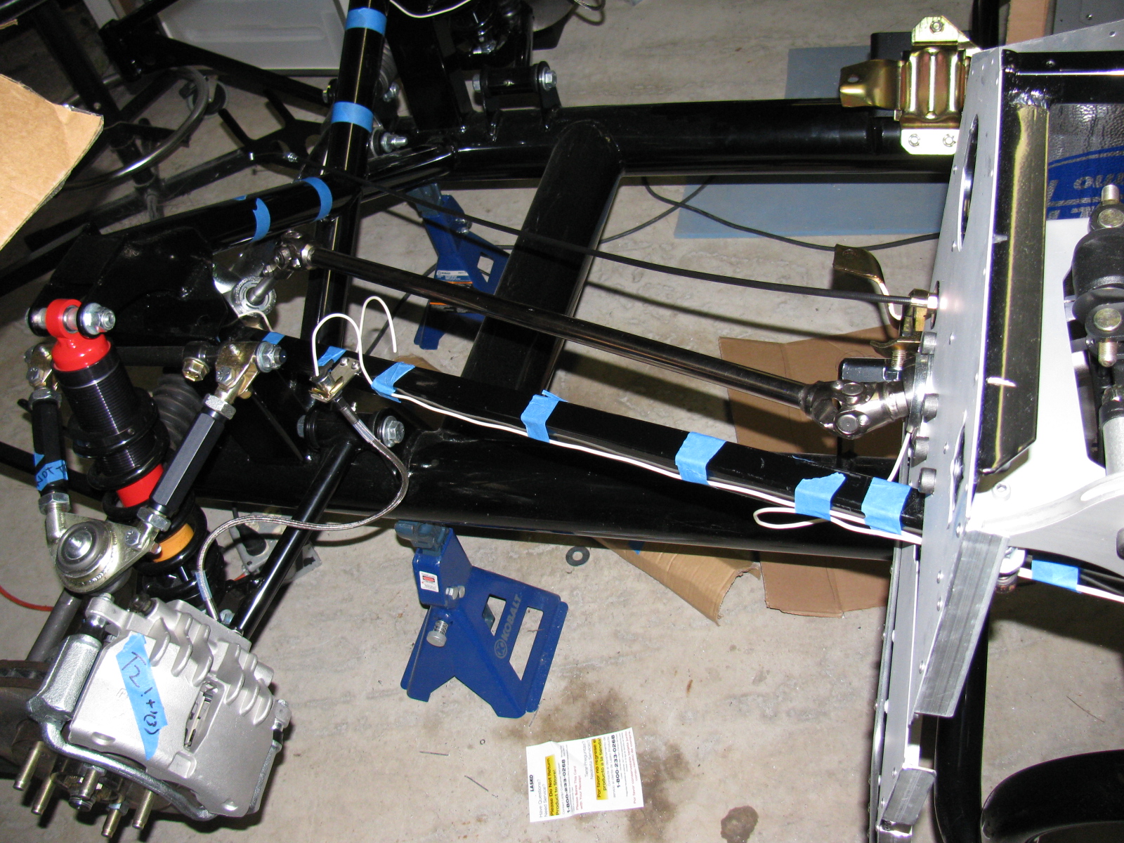
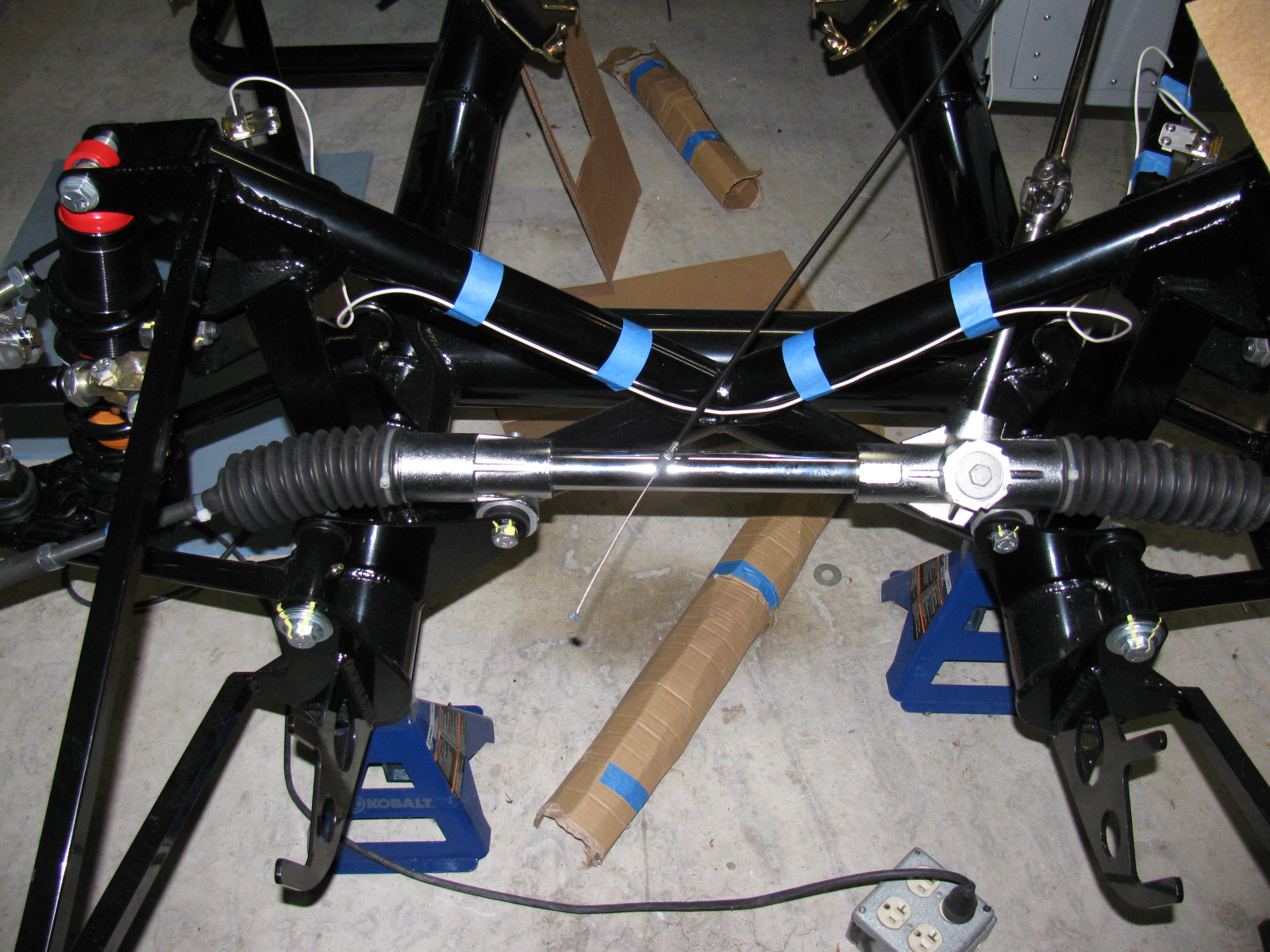
I start my brake line layout by marking the center of the span. This is the large rectangular tube going across the rear. The white wire (number 12 solid copper house wire) is used to make an extremely rough approximation of how the line will run.
-

-
Here you can see the white wire mock-up next to the steel brake line. The roughly Ohmega shape is centered above the IRS pumpkin.
-

-
I decided to run the rear brake line on the inside of the firewall. It will look cleaner in the engine bay and will help keep the line cooler.
-
-
I got lucky. I used a 60-inch line from the rear master cylinder, down the inside of the firewall, and ended up under the driver seat area. A second 60-inch line goes from the union to the rear brake tee. No custom length needed.
-
-
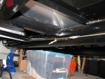
Here’s how the line goes up the support next to the lower rear sway arm. It will be slightly bent away from the chassis and held in place with the insulated line clips to prevent chafing.
-

-
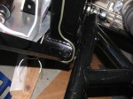
Going up to meet the rear brake flex line, driver’s side.
-
-
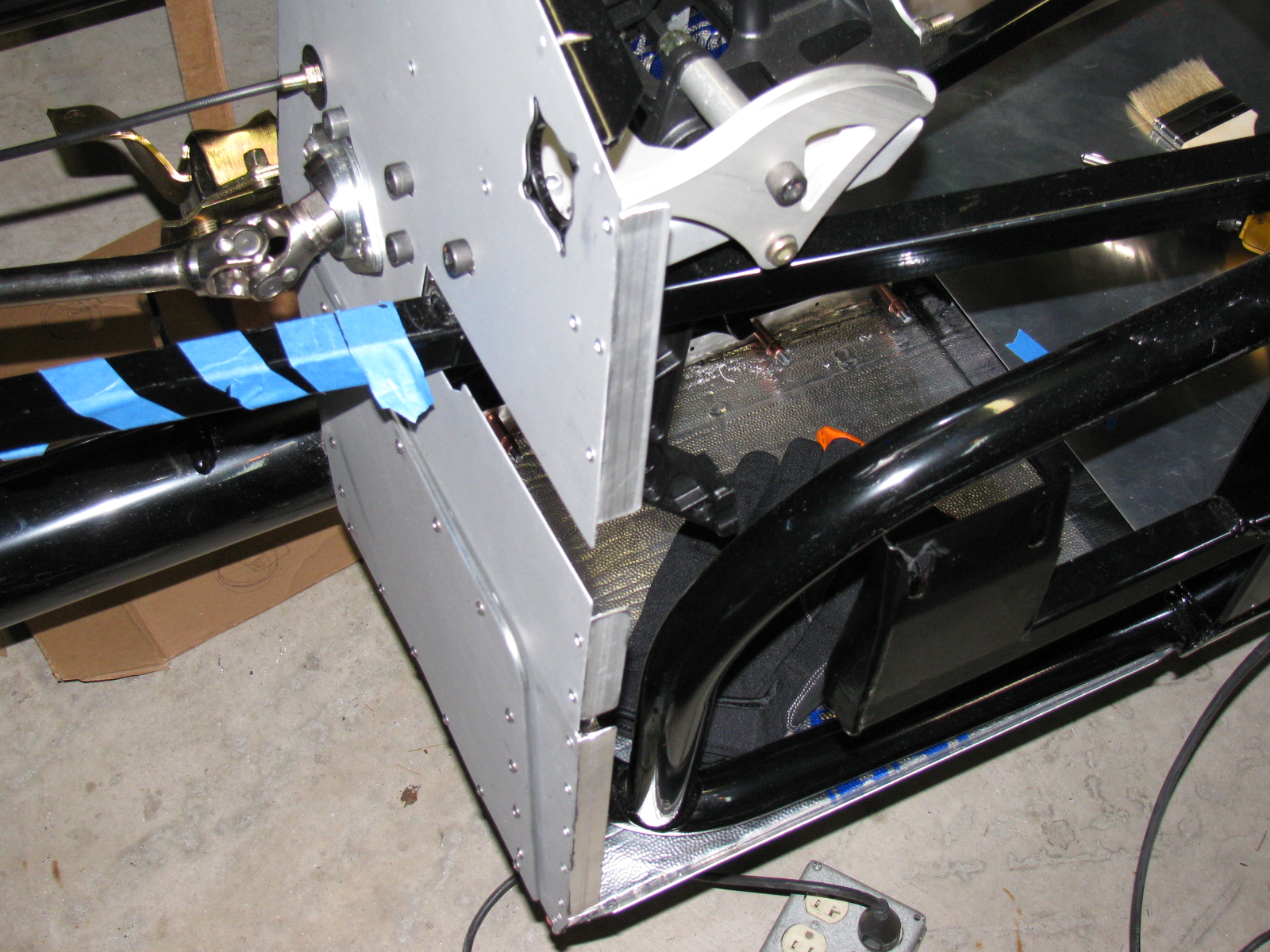
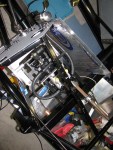
A peek into the pedal box – I am still not quite sure how this is going to work. The sheet metal on the right is going to be covered by the Coupe body, so this will be riveted – or screwed – into place. The open side on the left is going to have a one-piece cover. Will this provide enough access for brake balance and clutch cable adjustments?
-

-
Inside the pedal box, showing the front brake line going to the master cylinder. Not as pretty as some others I have seen, but I can always re-do this later, right?
-
-
Here is a view of the rear brake line going to the second master cylinder. I drilled out one rivet fastening the sheet aluminum to the firewall and replaced it with an 8-32 stainless steel screw. It holds the line clip as well as the firewall panel.
-
-
Next on the to-do list: Wiring
-

-
Next on the to-do list: Fuel tank.
For some reason, things on the Coupe take much longer than I expect. I decided to practice running the brake lines today. I used some scrap number 12 wire, cut into five-foot lengths. The copper wire is much more flexible than the brake lines, but at least I can do a mock-up before I bend the real thing.
I am using the “FFR Type 65 Coupe build site,” by cbergquist1 on Flickr.com as a reference – click here to see Chris’ section on brake lines. http://www.flickr.com/photos/51103049@N00/sets/72157622122325431/
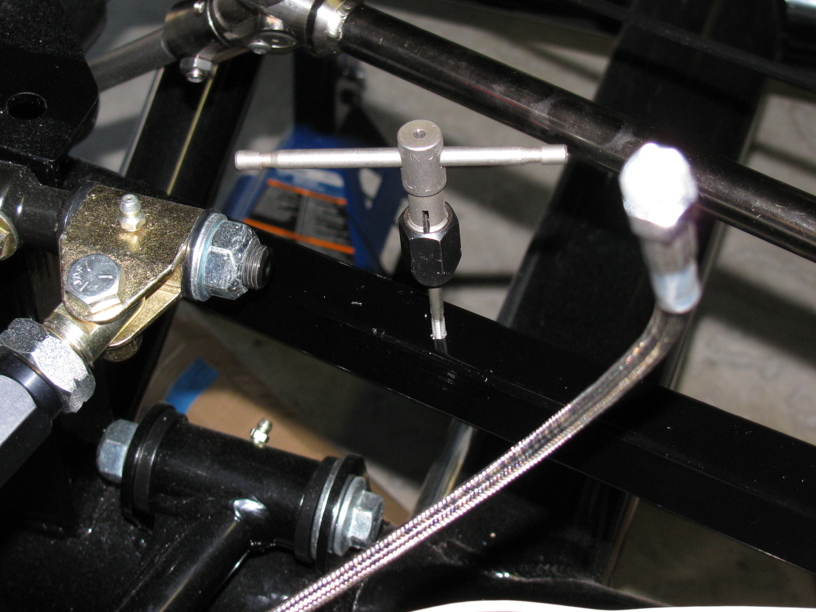
Just like Chris, I drilled and tapped holes for screws to mount the flex brake line mounts. I used 8-32 stainless steel button head screws. The Allen heads almost look like rivets.
Here are some pictures of my front brake line mock-up. . .


This is something weird. One of the mounting holes (on the left) was not punched out. I used an automatic center punch to knock the slug out.


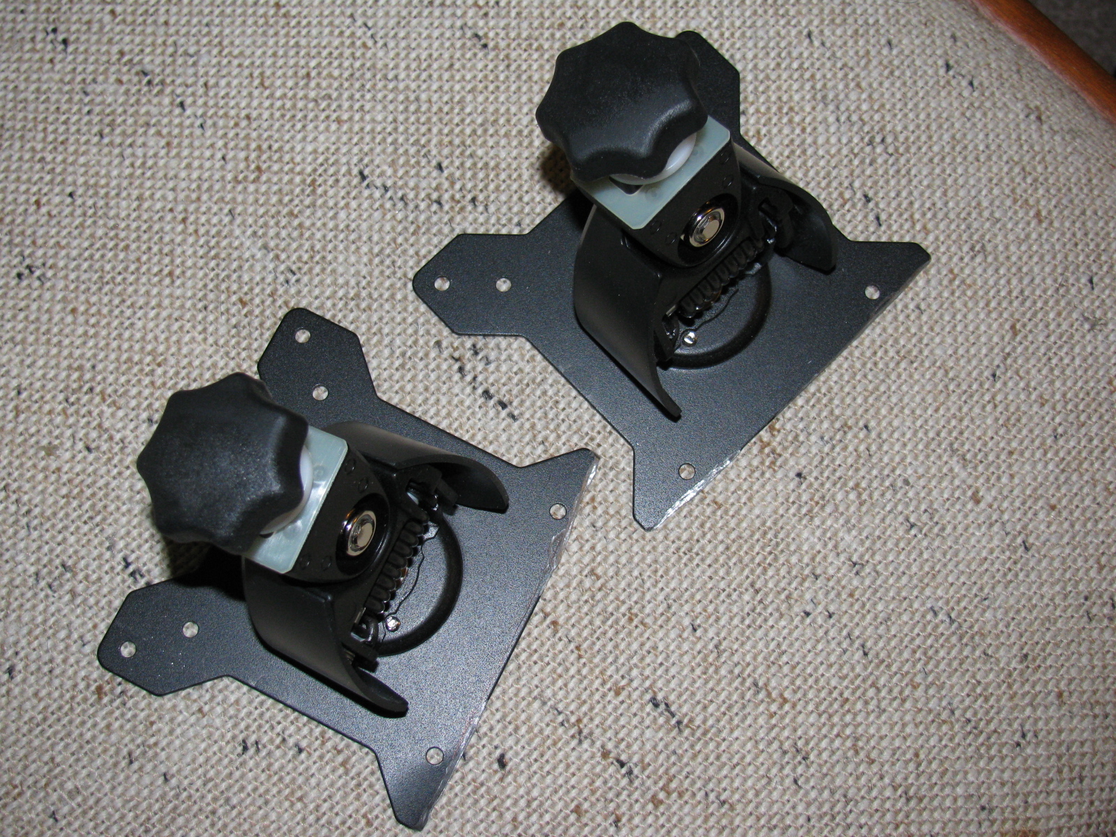
I took a time out to modify some monitor stand mounts for my office computer. The mounts were designed by monkeys, since they are useless and cannot be used out of the box. Actually, I should edit that statement, since I am not sure if the monitors or the monitor stands are wrong. In any case, some substantial cutting had to be done with my Dremel tool. I should have taken “before” and “after” pictures, but I wasn’t thinking. Here is a picture of the after-cutting operation. . . .

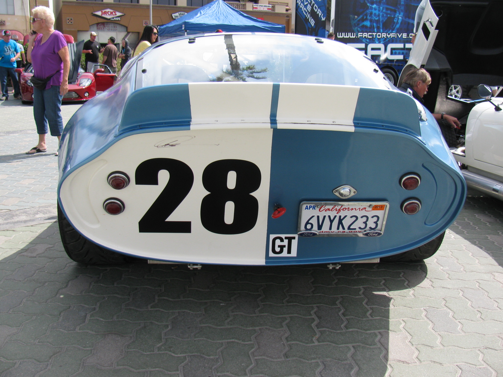
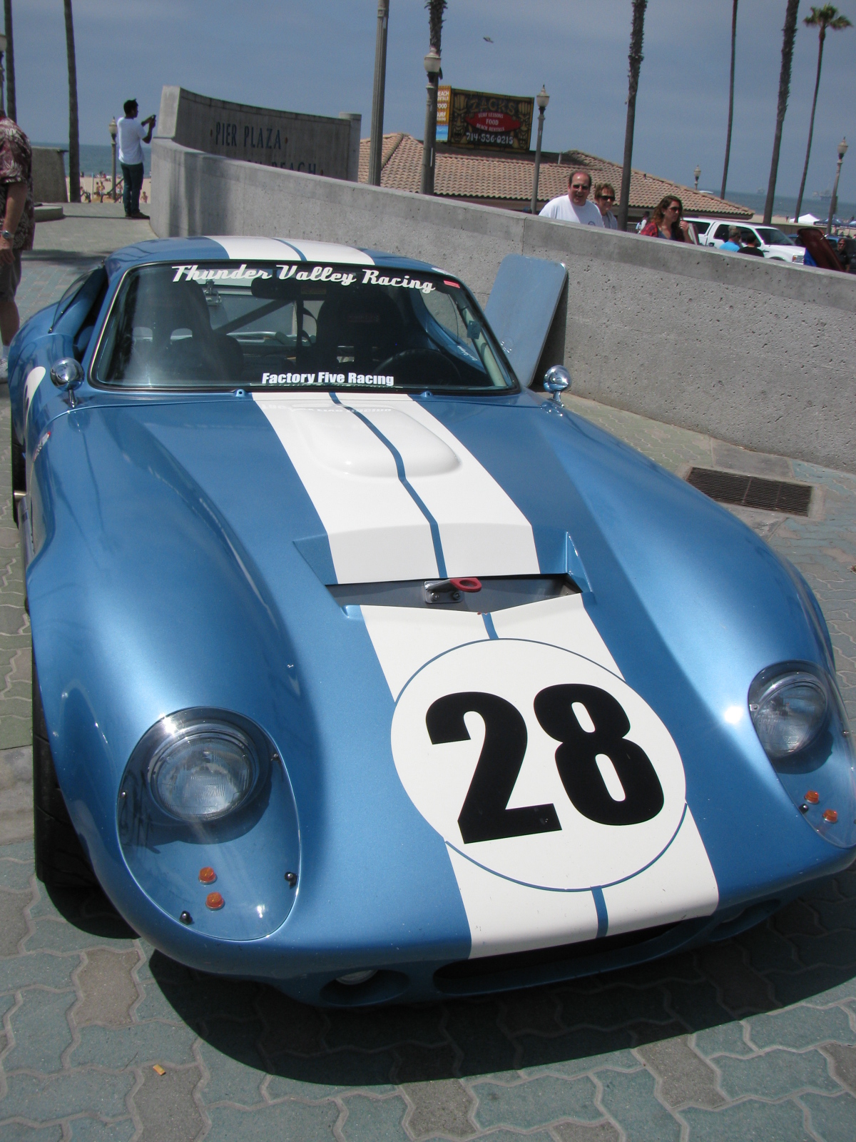
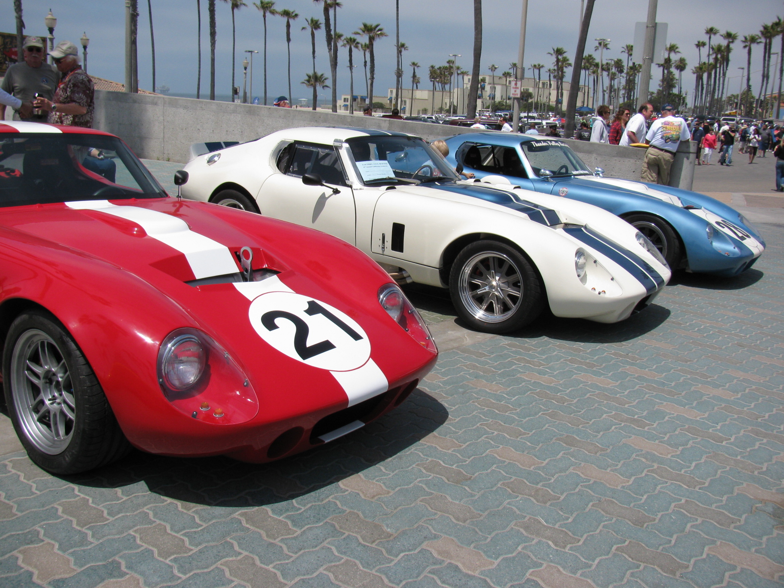
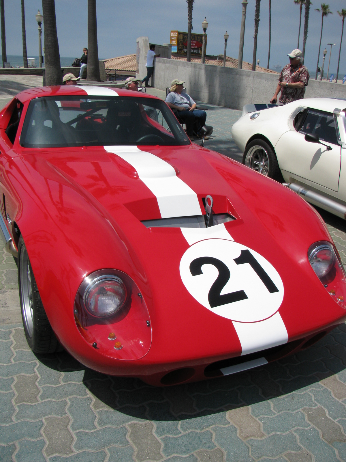
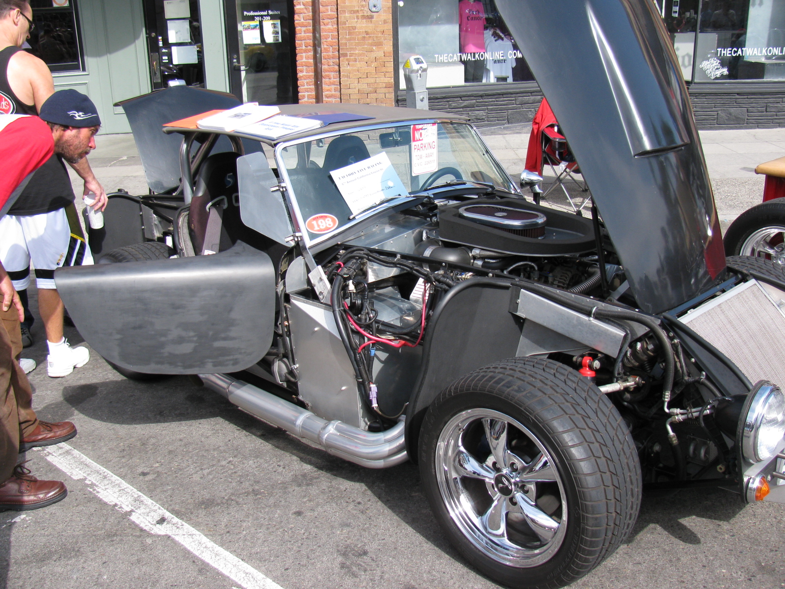
HUNTINGTON BEACH, Calif. — April 27, 2013 — Huntington Beach Pier Plaza and Main Street were filled with car enthusiasts and their hand-built sport cars from 9 am to 4 pm today. This was the sixth annual Factory Five Racing Huntington Beach Cruise-In which included over 100 Factory Five Racing cars, each one custom hand-built. Other custom and street cars were also on display, and included a vintage Chevrolet Corvette, and Ford GT.
Factory Five Racing is located in Wareham, MA and currently offers five component car kits, the Mk4 Roadster, the Type 65 Coupe, a classic ’33 Hot Rod, the GTM Supercar and the newest model called Project 818. Pricing varies depending on the kit configuration and accessories and options. In addition to the kit, builders supply their own engine, transmission, wheels and tires and finish and paint.
Dave Smith, president of Factory Five Racing, is a hands-on guy, and is involved in every aspect of his company… and is the friendliest person you’ll ever meet. He loves talking about his – and our – cars, and Dave says every time he meets people at these gatherings, he learns something new from each builder.
More information is available on the Factory Five Racing website, www.factoryfive.com
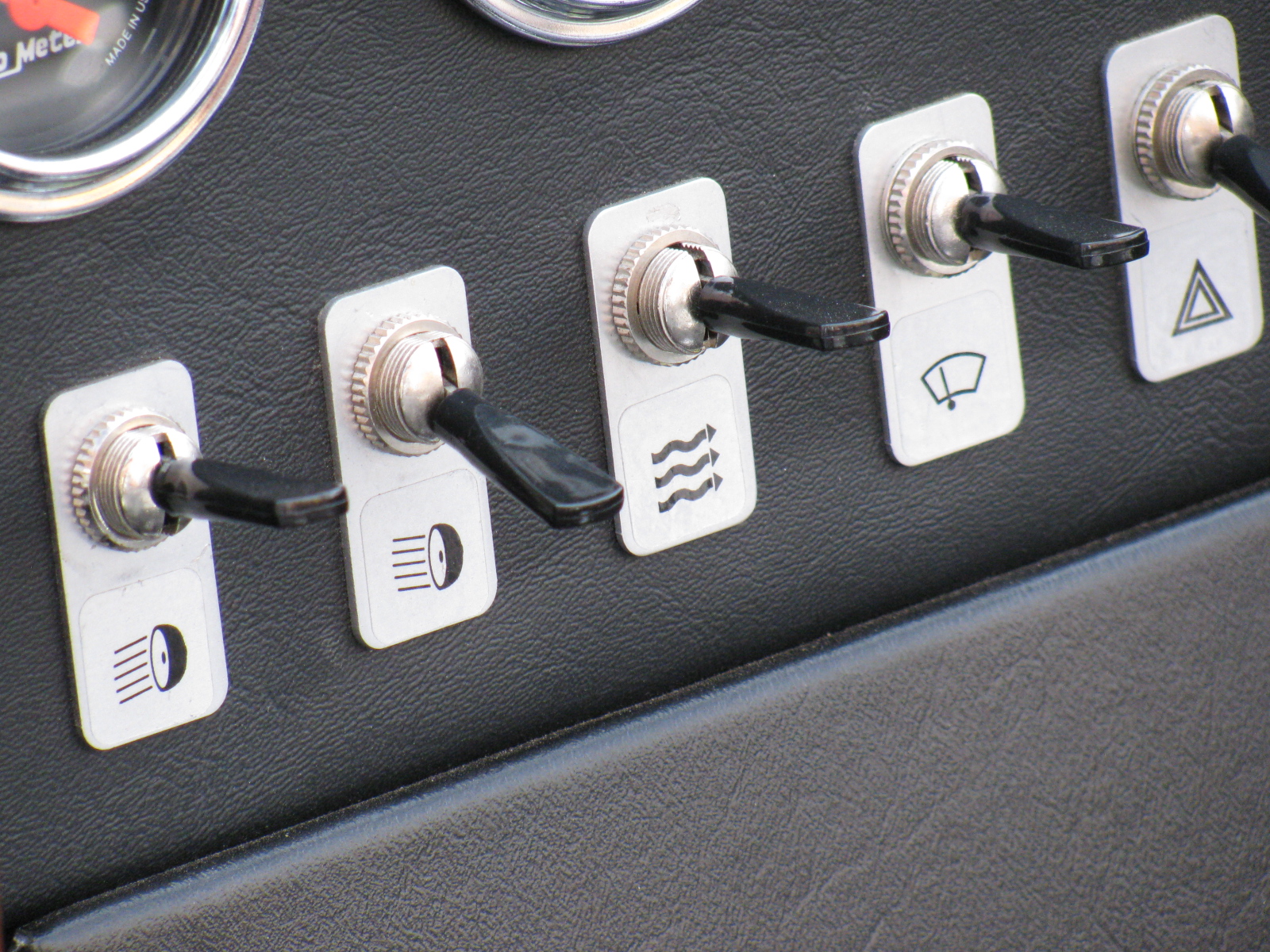
My mission at this year’s event: To gather more information on the E-brake cable routing, look at paint color combinations and get some more ideas for dashboard layouts.
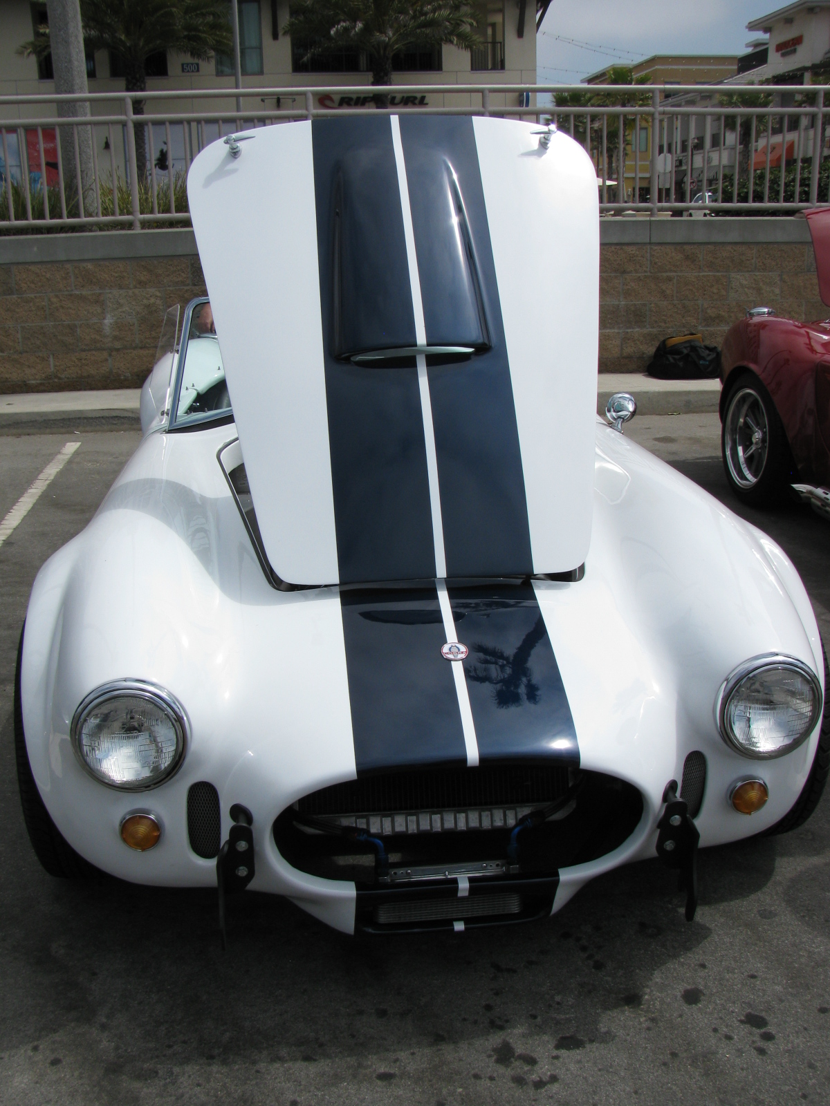
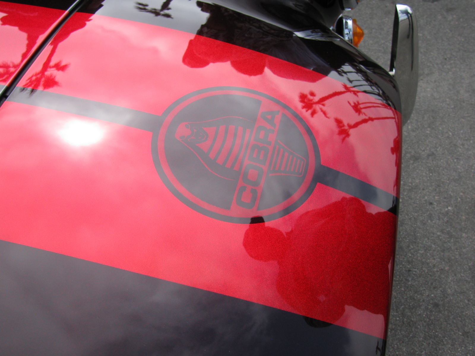
I had always planned on a white body/black or blue stripe Coupe, but after seeing these other paint jobs, I may change my mind. LED headlamps, cool-looking switch name plates, BRE side mirrors for the Coupe, honeycomb (hexagonal hole) screen for the side vents and other ideas are shown in these photos.
Thanks to everyone displaying and explaining and answering my questions about their cars today, and it was great to meet the Southern California – and other area – builders in person at this event.
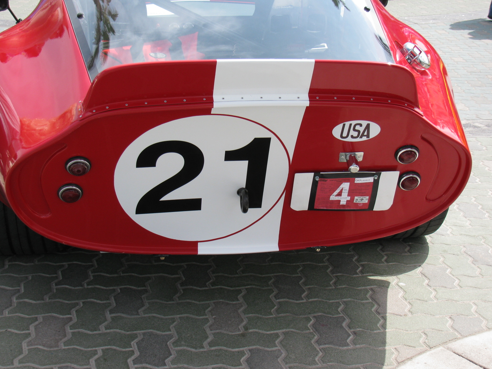
Here are some random images from today . . .


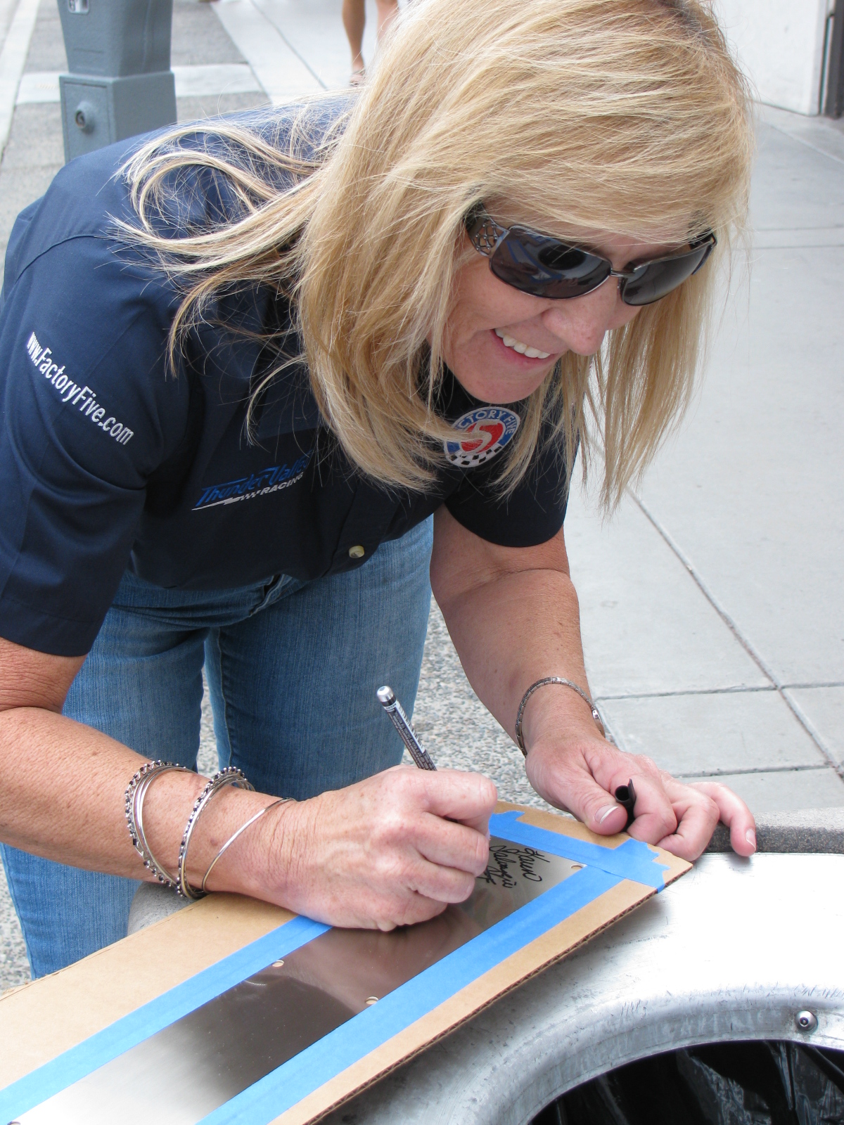
Above – Dave Smith, Factory Five Racing president, telling another great car story. . . Karen Salvaggio, Thunder Valley Racing Owner (and driver of the Type 65 Coupe number 28), signing my “signature plate” that will be mounted on my Type 65 Coupe dashboard – this will fill that big blank spot nicely. Take a look at Karen’s website and her blog posts for more informaton on her team and the cars they race. www.thundervalleyracing.com and http://thefactoryfiveforum.com/entry.php?346-Coupe-Challenge-Building-a-Legend


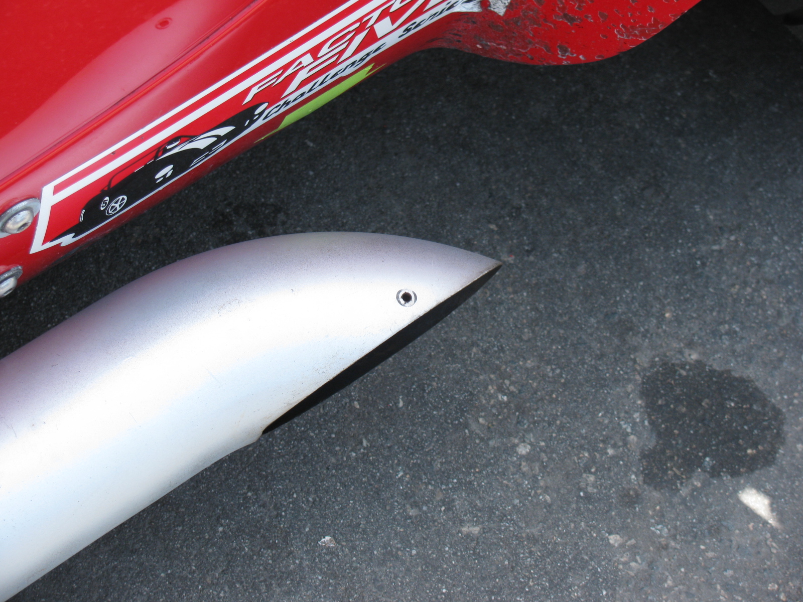
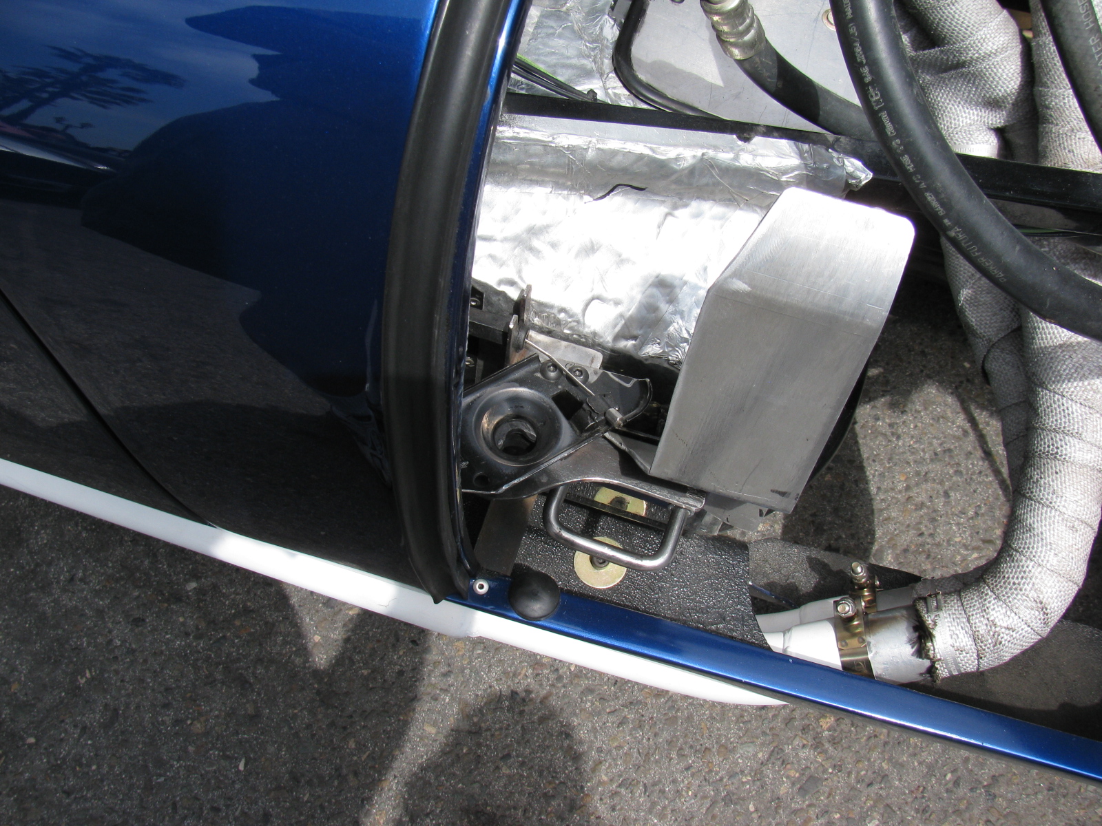
Anyone know what this hole is for on the Roadster exhaust?


6TH ANNUAL FACTORY FIVE HUNTINGTON BEACH CRUISE-IN click here
Here’s a short video of last year’s Moment of Thunder – click here
Some images from last year. . . .


. . . and a BBQ Dessert Experiment
Work on the passenger and driver side foot boxes continues on the Factory Five Racing Type 65 Coupe.
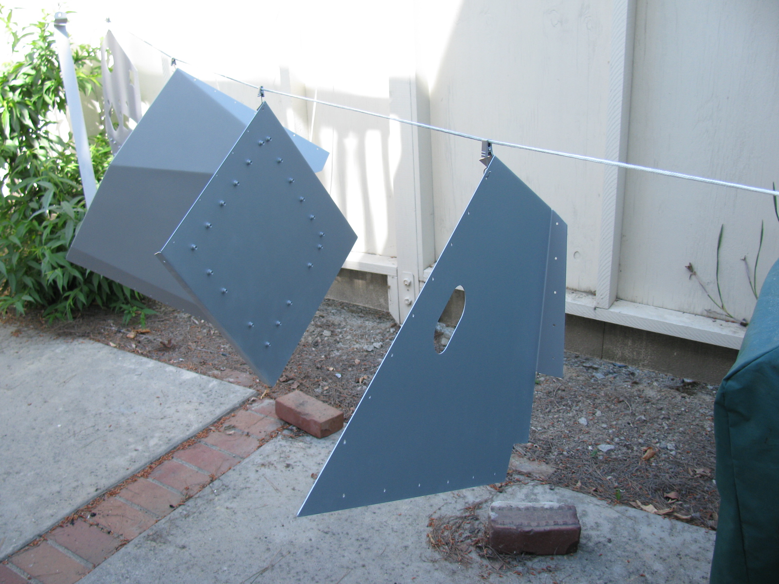
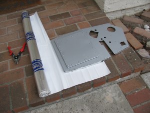
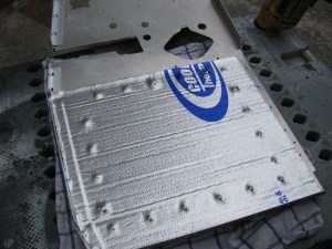
I painted the engine side of the panels with silver BBQ paint, and left the interior side un-painted, since all panels will be covered with Cool-It heat and sound barrier. Panels that face the exterior of the car – like the foot box floors and the trunk area, will be painted with RustOleum truck bed liner. It is a textured black finish that will also help reduce sound and noise. Here are some images. ..


On the left is a detail of one of the cookie sheet heat shields, fastened to the firewall with 8-32 riv-nuts. The spacing is about one-quarter-inch. On the right is a view of the top of the heat shield, showing the nicely rolled edge.


Passenger side foot box appears on the left of the photo above. The photo on the right shows a closer look at the passenger foot box.


Photos above: Passenger foot box, before and after installing the Cool-It mats.


Above left: The top seam on the passenger foot box – this will be either trimmed or a strip of aluminum will be used to cover the mis-match. On the right, I added srtips of aluminum angle to the outer wall of the driver side foor box. This should make the outer wall easier to install.
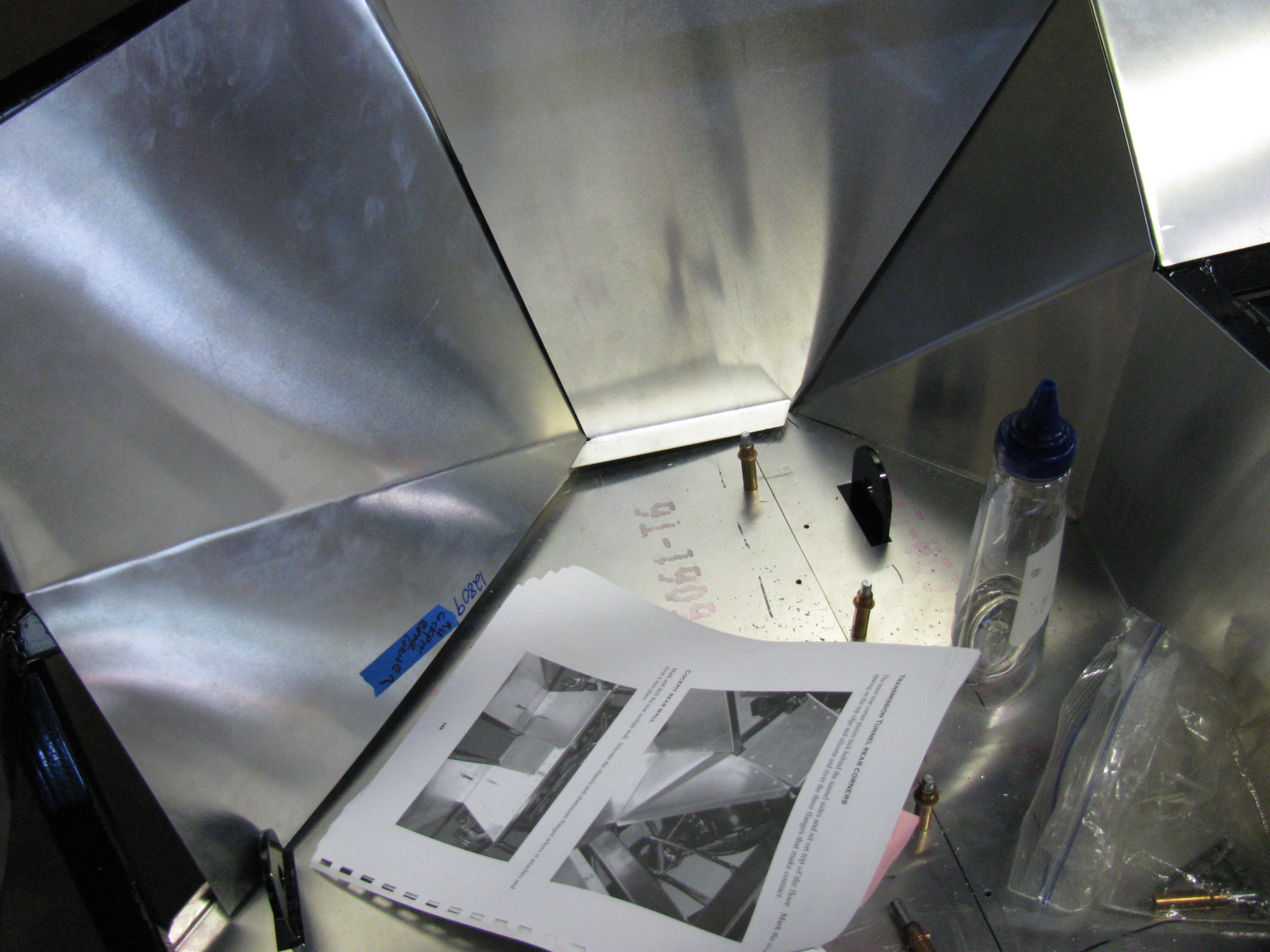
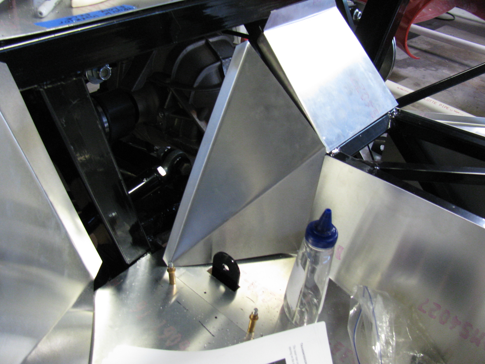
The next series of photos show how the interior panels go into place. The un-finished aluminum is difficult to photograph, I wish the manual would include an exploded view of the panels and how they fit into place. This is a complex jigsaw puzzle, and many of the parts must be flexed, trimmed and pulled into place. Clecos really help. This is one area where the manual offers good advice – the sections fit best when you follow the order outlined in the manual. Although many of the panels are marked with a part number, they do not indicate the orientation of the panel.
The foot box floors were very difficult to fit into place, so I sliced them into sections. If you look carefully you can see the saw kerfs (seams) on the floor panels. I chose the cuts carefully, in order to make sure I would have something solid to rivet to. In the areas without any supporting chassis tubes, I will install strips of aluminum bar stock.
The panels will be permanently attached later with silicone adhesive and rivets – at this stage, the panels are being “dry-fitted” with clecos to make sure everything is properly in place.


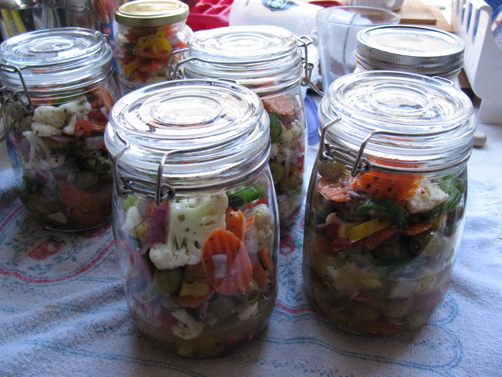
Somewhere during this building session, I made some time to pack my hot giardiniera into jars, and made a few deliveries. . .
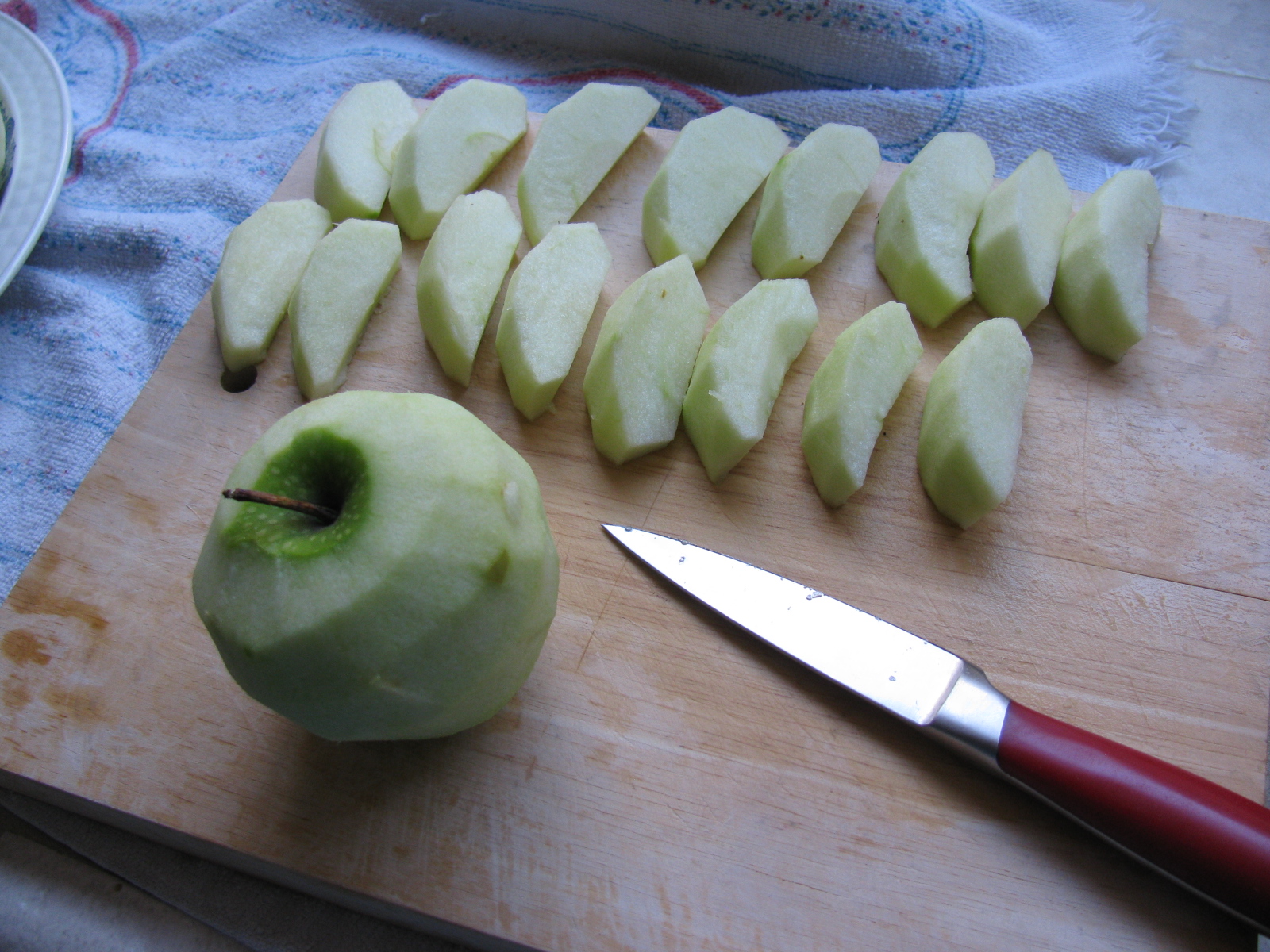
I also managed to do some BBQ experiments. This time I baked some apple turn-overs in the Big Green Egg. They turned out OK, but could be better. They are like just-right bites of apple pie. Here are some pictures. . .


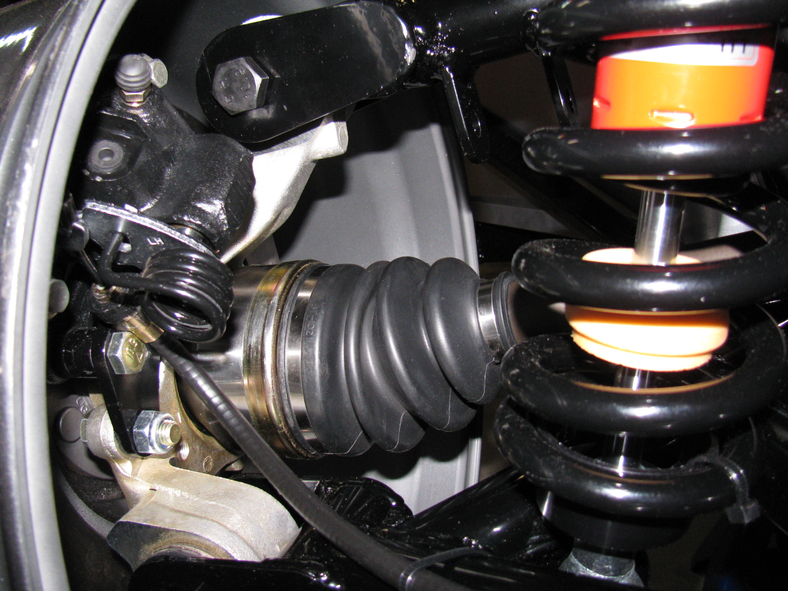
I forgot to add notes and images from the IRS (standard width) brake installation. Here are some images, plus a link to a YouTube video…


As you can see in the picture above left, an open end wrench can go onto the caliper mounting bolt. This was a button head Allen screw in the past. The emergency brake cable seems very tight and has a sharp bend, but this seems to work OK.


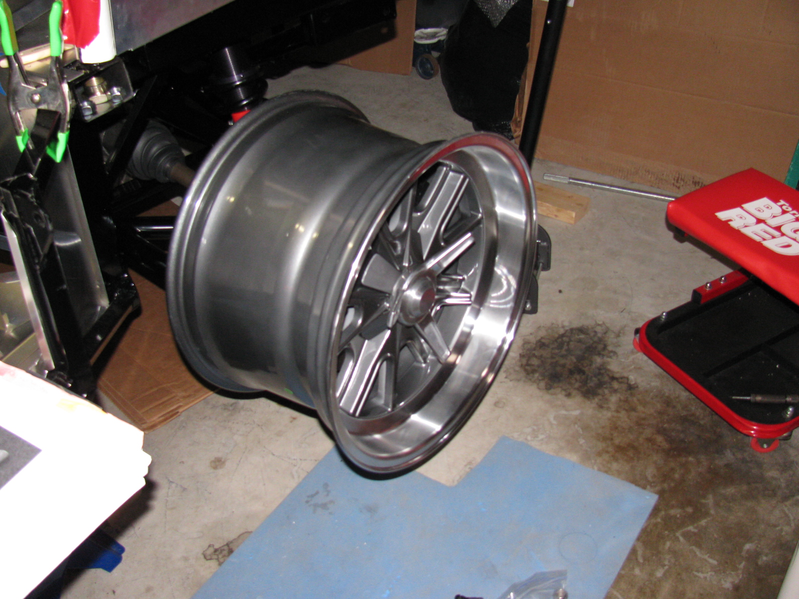
The vintage Halibrand replica wheels fit nicely over the axle-hub-brake assembly, but I don’t have tires yet.

The rear wheels are 17-inches by 10.5-inches, and the tires will be 275 / 40ZR17, probably BF Goodrich g-Force Sport Comp 2, but not sure yet.
A Silent Movie: Rear Brake Installation
Oh – almost forgot. Here is a silent movie about the rear brake installation:
http://www.youtube.com/watch?v=bVcX8-Nnqfo
It’s been a few weeks since I posted an update. Some people have been asking for some news, so here we go. . .
I am preparing the chassis so I can install the engine and transmission. This means that I have to finish the firewall, which means prepping and painting the foot boxes and routing and mounting the brake and fuel lines.
I decided to finish the engine bay with silver Rust-Oleum high temperature BBQ paint. This is a change from my thoughts on powder coating and appliance epoxy. . . The appliance epoxy has an upper temperature limit of 200 degrees F, and I think engine bay heat is higher than an oven. The BBQ paint is good for 1200 degrees F or something like that. Depending on how the engine bay looks, I may strip everything off and re-finish with powder coat later. But for now, the silver BBQ paint looks OK. The nice weather last week allowed me to do some rattle-can spraying outside.
I permanently mounted my first aluminum panel – the driver’s side foot box front. I am using Permatex Ultra Black number 2105 silicone adhesive. This is what Kirkham Motors uses for their builds, so I will use what they use. It can be used as an adhesive as well as a gasket, so this extends its usefulness around the shop.
References: Kirkham online build and Permatex Ultra Black goop


Above right is a close-up of the BBQ paint finish on one of the pedal box panels. Looks OK. There is a slight texture to the finish. The color is actually silver, the blue-ish tint is probably from sunlight diffracting from somewhere.

Above left, a “dry fit” of the driver side foot box front panel. You can see the cookie sheet heat shields in place. Above right, using the panel as a pattern to cut the insulation mat – just place the panel onto the backing side of the mat, press down and then cut with shears or a knife. Final trimming is done with a utility knife.
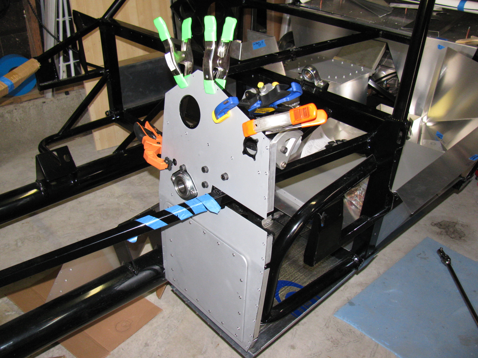
Cool-It heat and sound insulation is applied to the interior side of the foot box panel. The “bubbles” you see are from the riv-nuts and screws poking out from the other side. On the right, I wanted to make sure the adhesive stuck properly at the top of the panel, so I used some clamps to squeeze evenly. My good friend Norm Abram always says, “You can never have too many clamps.”
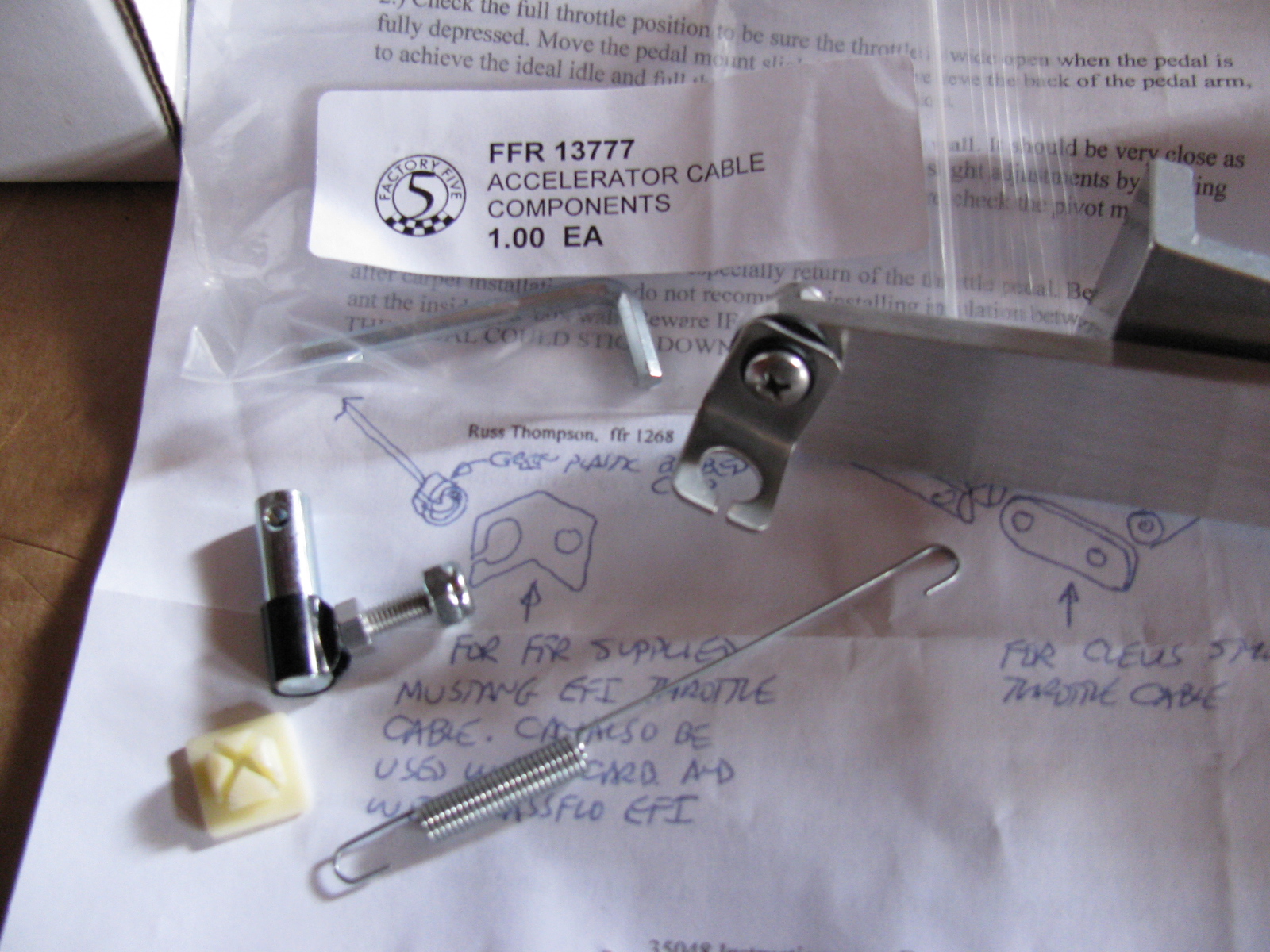
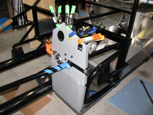
The Accelerator Cable and Pedal
I mounted the accelerator cable as well as the Russ Thompson gas pedal, sold by Breeze Automotive. The instructions are different from what is being supplied by Factory Five Racing now. (I am getting used to this. . . )

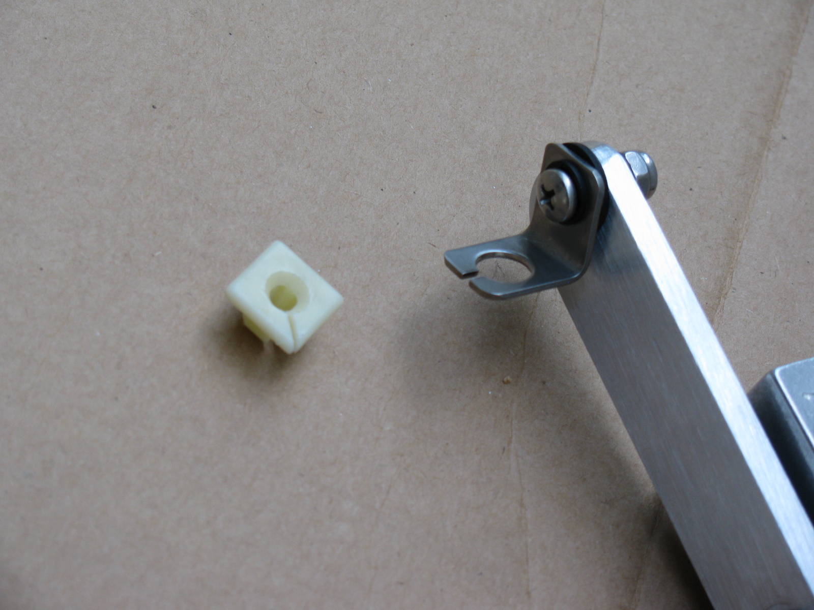
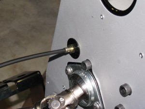
The picture above shows some of the gas pedal mounting parts that come with the Complete Kit. The Thompson / Breeze pedal instructions say something about a “green plastic barbed clip” at the end of the throttle cable. This green thing is no longer what comes with the kit. Instead, there is a little square “plug” that is too big to fit into the pedal mount.
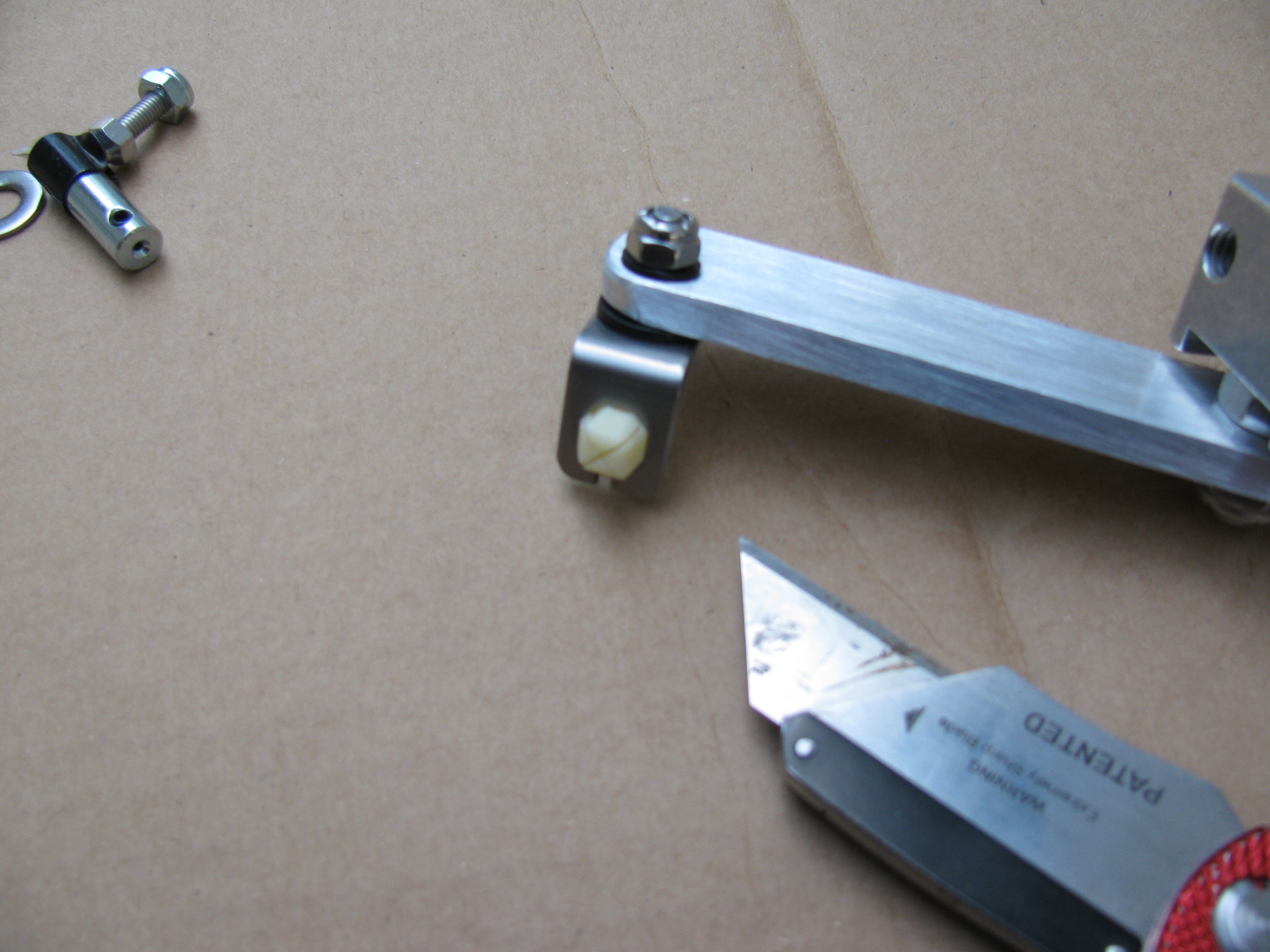
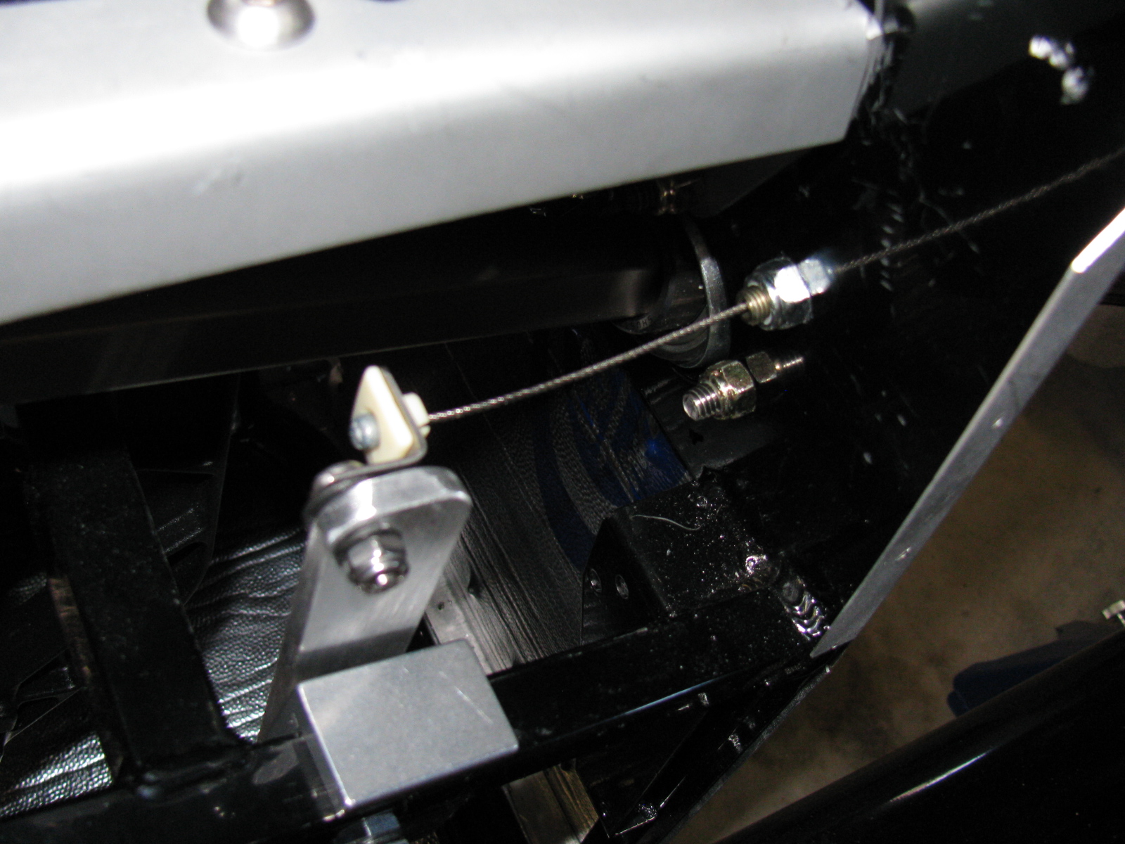
Rather than cutting off the ball-end at the throttle cable or drill a bigger hole in the mount, I decided to carefully cut some of the plastic from the center barb so it would fit snugly into the mounting hole – not much has to be shaved off, it is something like a sixteenth of an inch or so. Then I made a slit in the square plastic thing as shown so the cable could slip in with the ball intact.


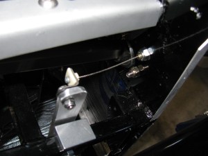
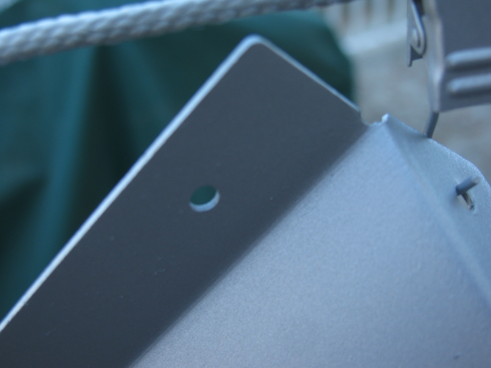
As you can see above, I added a fender washer (painted black) to the throttle cable mounting point, this is just for looks.
This is Irritating
For some reason, this bothered me today, but then I realized not many tubes of caulk gun goop come with caps. Anyway, I used a pen cap to close the tube. I hope this works, I only needed a few beads for this build session.
Some Great Looking Door Panels on Order!
I ordered a set of leather door panels from Levy Racing earlier this week. They look like this: