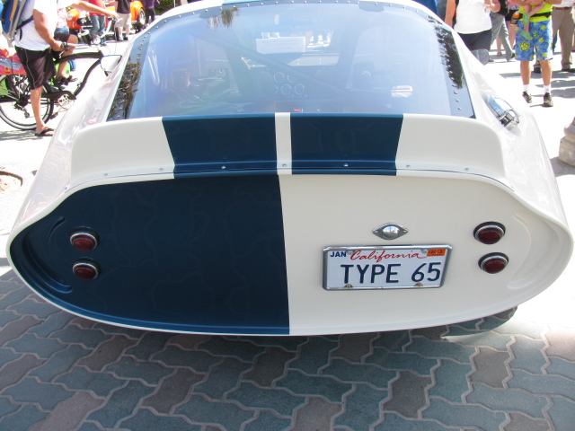
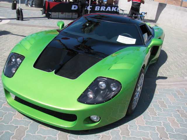
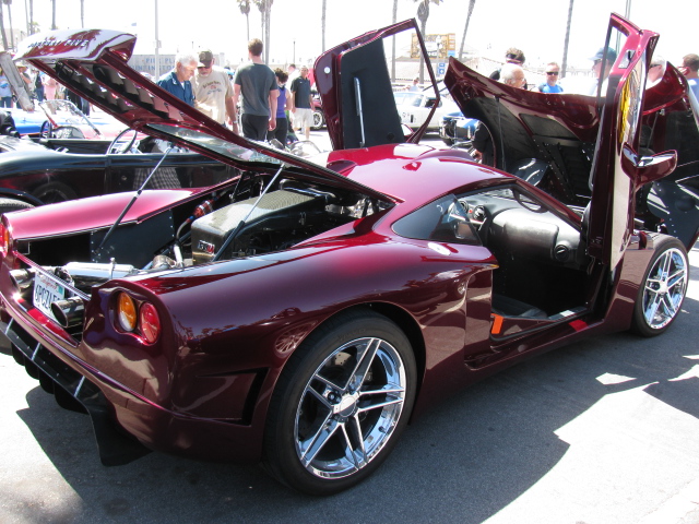
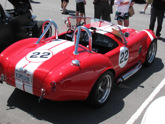
6TH ANNUAL FACTORY FIVE HUNTINGTON BEACH CRUISE-IN click here
Here’s a short video of last year’s Moment of Thunder – click here
Some images from last year. . . .


6TH ANNUAL FACTORY FIVE HUNTINGTON BEACH CRUISE-IN click here
Here’s a short video of last year’s Moment of Thunder – click here
Some images from last year. . . .
. . . and a BBQ Dessert Experiment
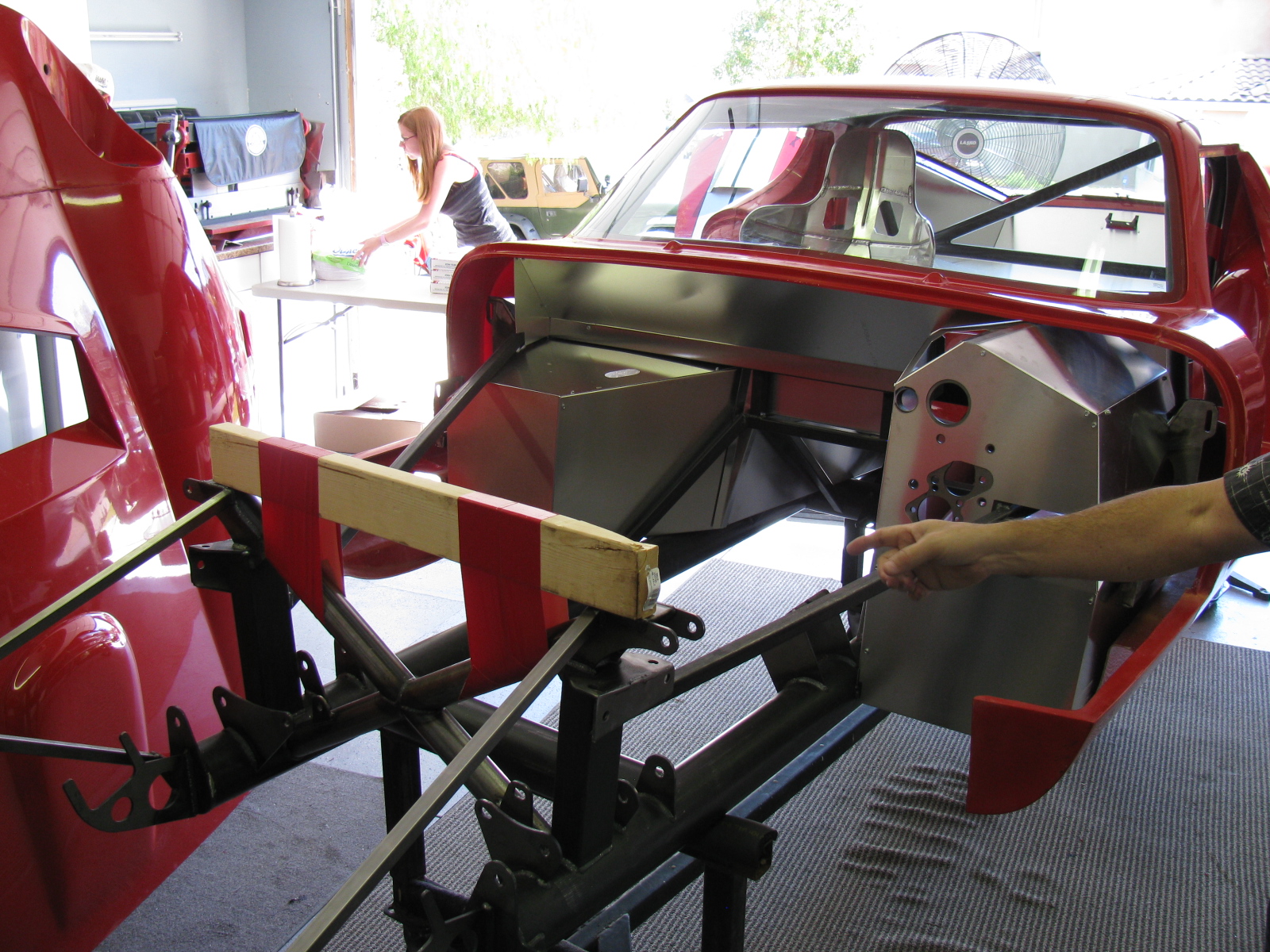
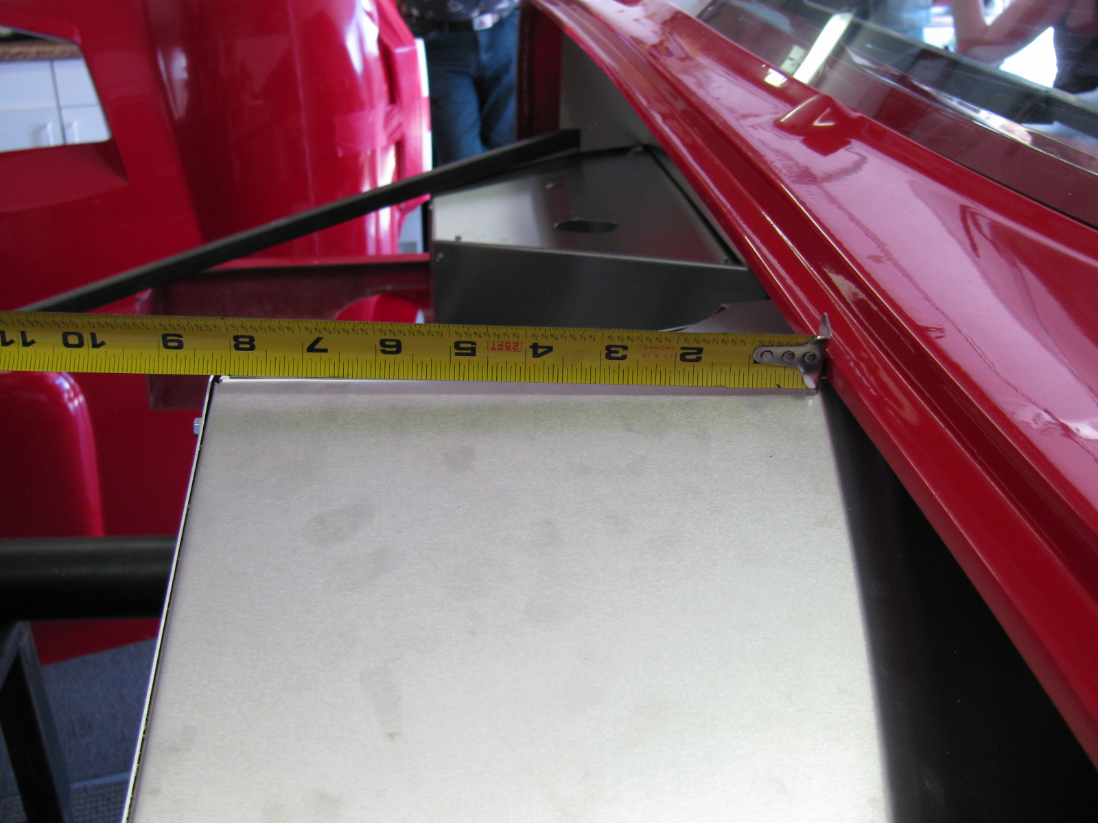
Work on the passenger and driver side foot boxes continues on the Factory Five Racing Type 65 Coupe.
I painted the engine side of the panels with silver BBQ paint, and left the interior side un-painted, since all panels will be covered with Cool-It heat and sound barrier. Panels that face the exterior of the car – like the foot box floors and the trunk area, will be painted with RustOleum truck bed liner. It is a textured black finish that will also help reduce sound and noise. Here are some images. ..
On the left is a detail of one of the cookie sheet heat shields, fastened to the firewall with 8-32 riv-nuts. The spacing is about one-quarter-inch. On the right is a view of the top of the heat shield, showing the nicely rolled edge.

Passenger side foot box appears on the left of the photo above. The photo on the right shows a closer look at the passenger foot box.


Photos above: Passenger foot box, before and after installing the Cool-It mats.

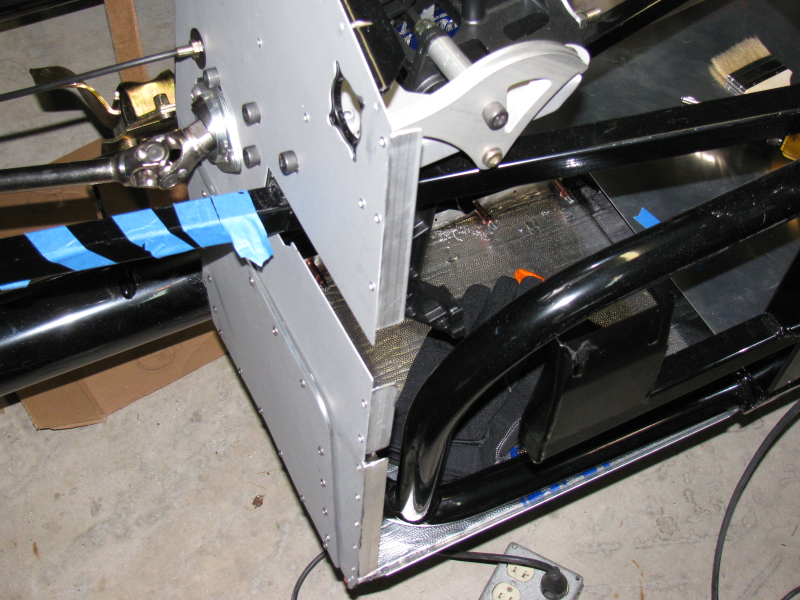
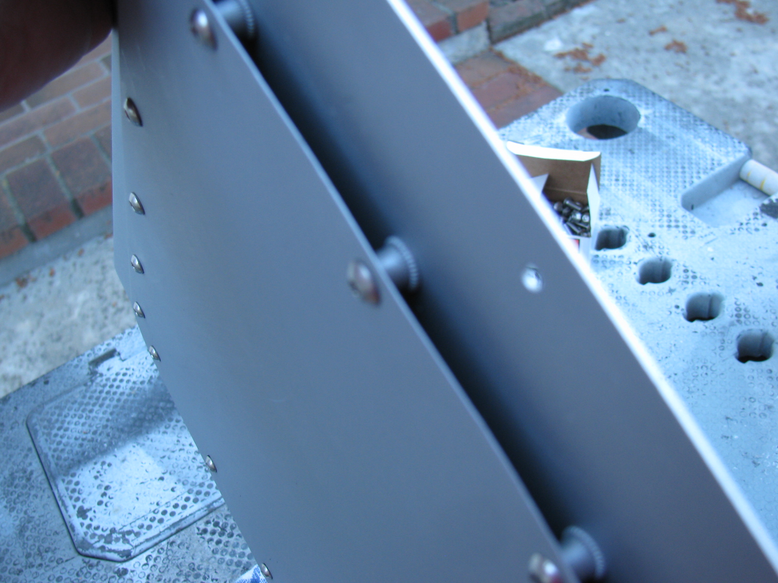
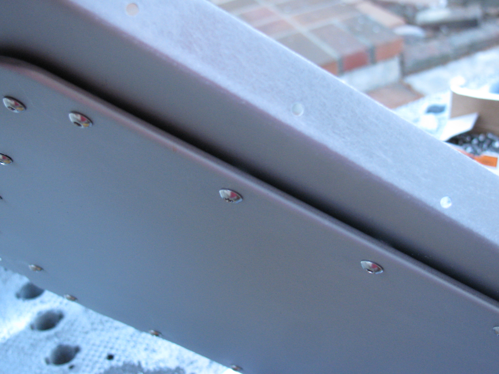
Above left: The top seam on the passenger foot box – this will be either trimmed or a strip of aluminum will be used to cover the mis-match. On the right, I added srtips of aluminum angle to the outer wall of the driver side foor box. This should make the outer wall easier to install.
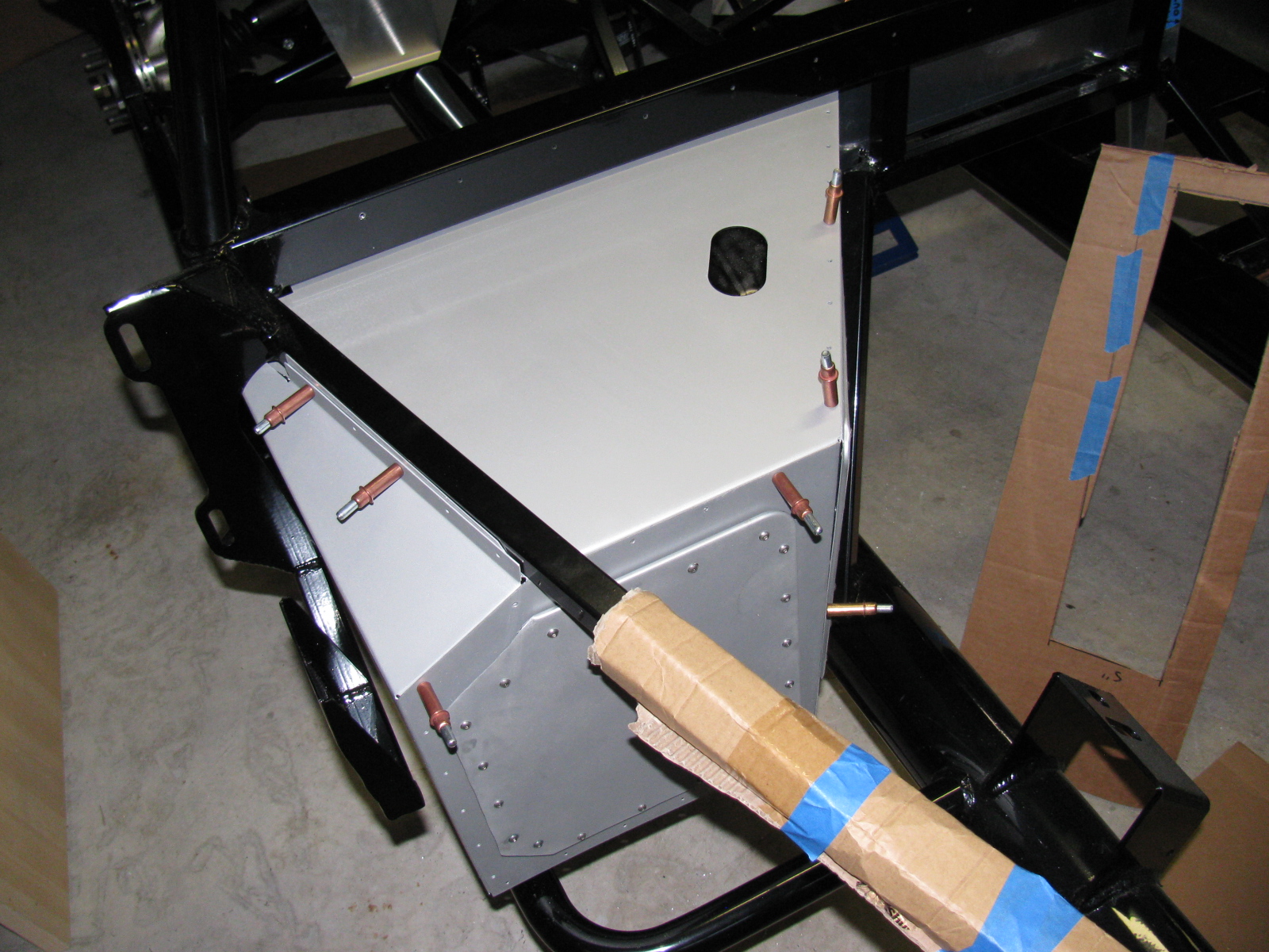
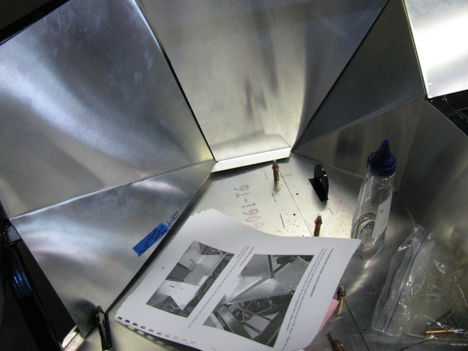
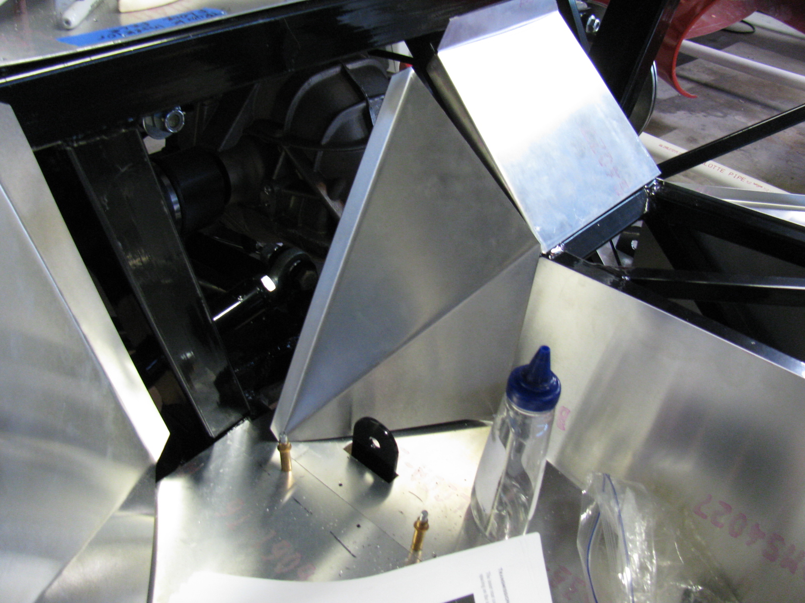
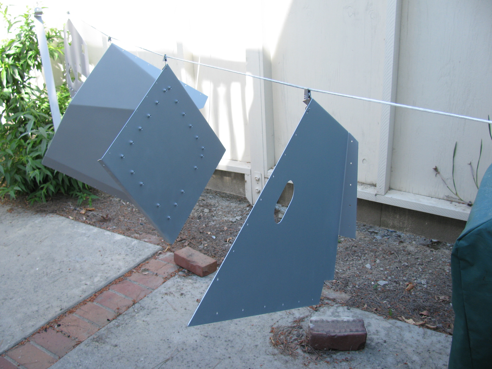
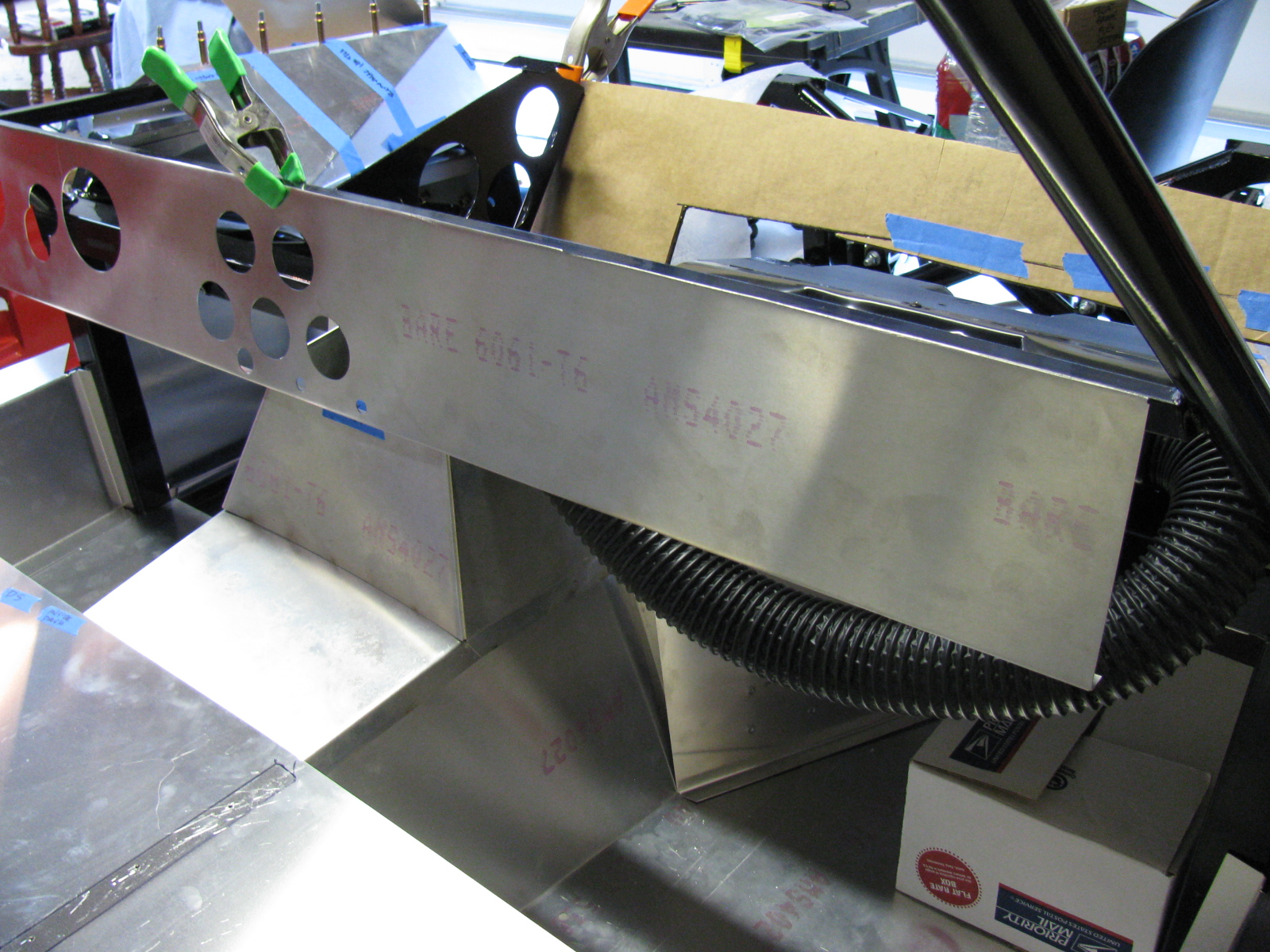
The next series of photos show how the interior panels go into place. The un-finished aluminum is difficult to photograph, I wish the manual would include an exploded view of the panels and how they fit into place. This is a complex jigsaw puzzle, and many of the parts must be flexed, trimmed and pulled into place. Clecos really help. This is one area where the manual offers good advice – the sections fit best when you follow the order outlined in the manual. Although many of the panels are marked with a part number, they do not indicate the orientation of the panel.
The foot box floors were very difficult to fit into place, so I sliced them into sections. If you look carefully you can see the saw kerfs (seams) on the floor panels. I chose the cuts carefully, in order to make sure I would have something solid to rivet to. In the areas without any supporting chassis tubes, I will install strips of aluminum bar stock.
The panels will be permanently attached later with silicone adhesive and rivets – at this stage, the panels are being “dry-fitted” with clecos to make sure everything is properly in place.


Somewhere during this building session, I made some time to pack my hot giardiniera into jars, and made a few deliveries. . .
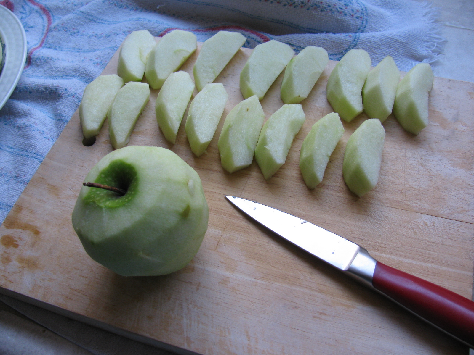
I also managed to do some BBQ experiments. This time I baked some apple turn-overs in the Big Green Egg. They turned out OK, but could be better. They are like just-right bites of apple pie. Here are some pictures. . .


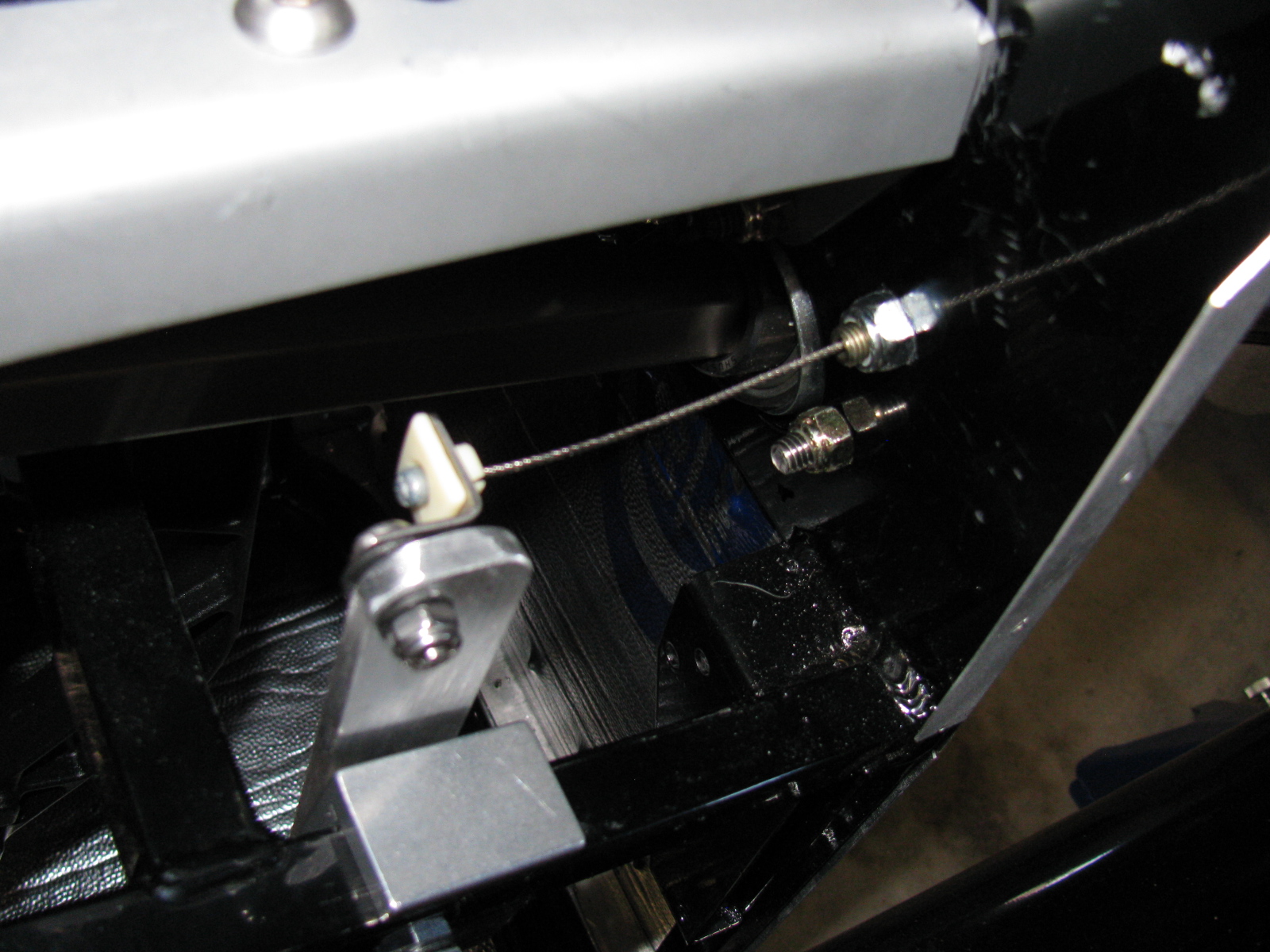
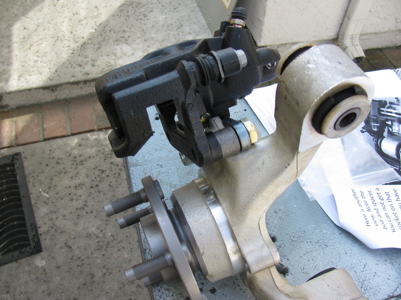
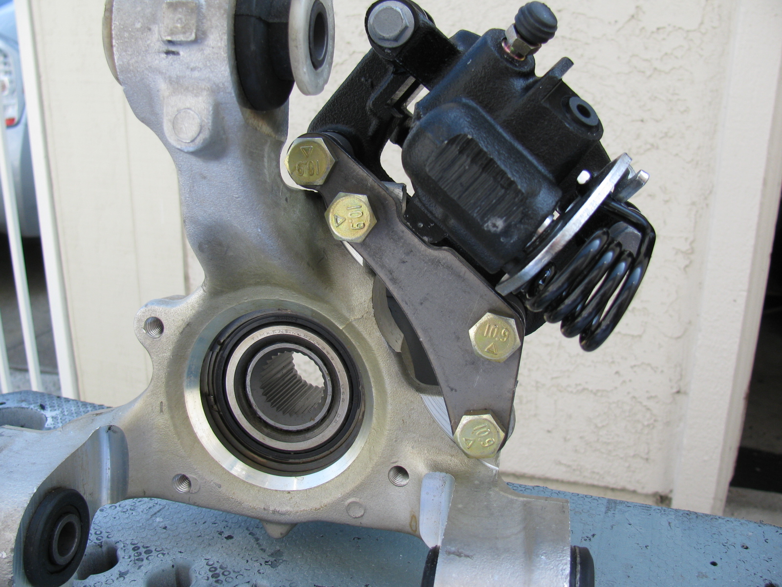
I forgot to add notes and images from the IRS (standard width) brake installation. Here are some images, plus a link to a YouTube video…


As you can see in the picture above left, an open end wrench can go onto the caliper mounting bolt. This was a button head Allen screw in the past. The emergency brake cable seems very tight and has a sharp bend, but this seems to work OK.
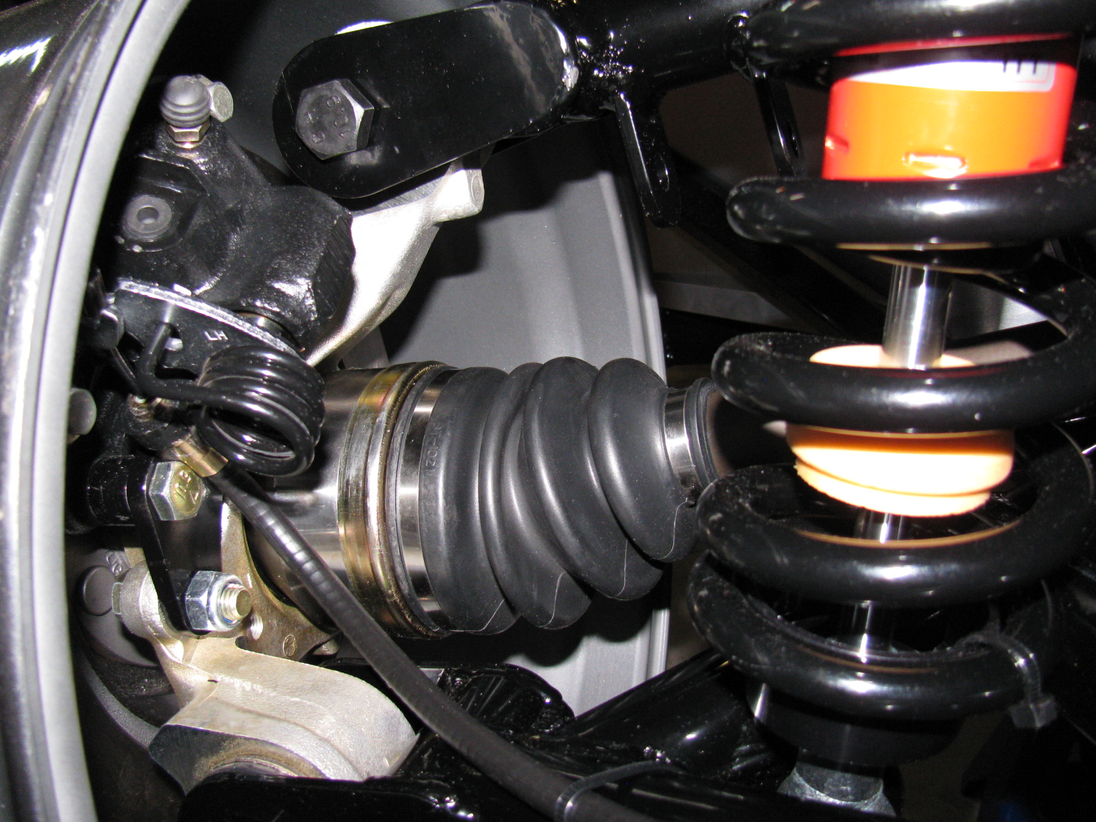
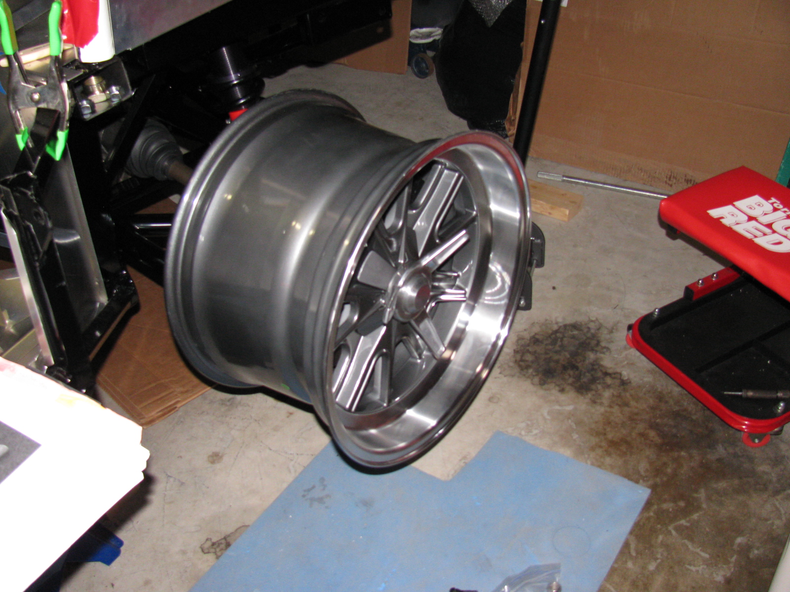
The vintage Halibrand replica wheels fit nicely over the axle-hub-brake assembly, but I don’t have tires yet.

The rear wheels are 17-inches by 10.5-inches, and the tires will be 275 / 40ZR17, probably BF Goodrich g-Force Sport Comp 2, but not sure yet.
A Silent Movie: Rear Brake Installation
Oh – almost forgot. Here is a silent movie about the rear brake installation:
http://www.youtube.com/watch?v=bVcX8-Nnqfo
It’s been a few weeks since I posted an update. Some people have been asking for some news, so here we go. . .
I am preparing the chassis so I can install the engine and transmission. This means that I have to finish the firewall, which means prepping and painting the foot boxes and routing and mounting the brake and fuel lines.
I decided to finish the engine bay with silver Rust-Oleum high temperature BBQ paint. This is a change from my thoughts on powder coating and appliance epoxy. . . The appliance epoxy has an upper temperature limit of 200 degrees F, and I think engine bay heat is higher than an oven. The BBQ paint is good for 1200 degrees F or something like that. Depending on how the engine bay looks, I may strip everything off and re-finish with powder coat later. But for now, the silver BBQ paint looks OK. The nice weather last week allowed me to do some rattle-can spraying outside.
I permanently mounted my first aluminum panel – the driver’s side foot box front. I am using Permatex Ultra Black number 2105 silicone adhesive. This is what Kirkham Motors uses for their builds, so I will use what they use. It can be used as an adhesive as well as a gasket, so this extends its usefulness around the shop.
References: Kirkham online build and Permatex Ultra Black goop
Above right is a close-up of the BBQ paint finish on one of the pedal box panels. Looks OK. There is a slight texture to the finish. The color is actually silver, the blue-ish tint is probably from sunlight diffracting from somewhere.


Above left, a “dry fit” of the driver side foot box front panel. You can see the cookie sheet heat shields in place. Above right, using the panel as a pattern to cut the insulation mat – just place the panel onto the backing side of the mat, press down and then cut with shears or a knife. Final trimming is done with a utility knife.

Cool-It heat and sound insulation is applied to the interior side of the foot box panel. The “bubbles” you see are from the riv-nuts and screws poking out from the other side. On the right, I wanted to make sure the adhesive stuck properly at the top of the panel, so I used some clamps to squeeze evenly. My good friend Norm Abram always says, “You can never have too many clamps.”
The Accelerator Cable and Pedal
I mounted the accelerator cable as well as the Russ Thompson gas pedal, sold by Breeze Automotive. The instructions are different from what is being supplied by Factory Five Racing now. (I am getting used to this. . . )
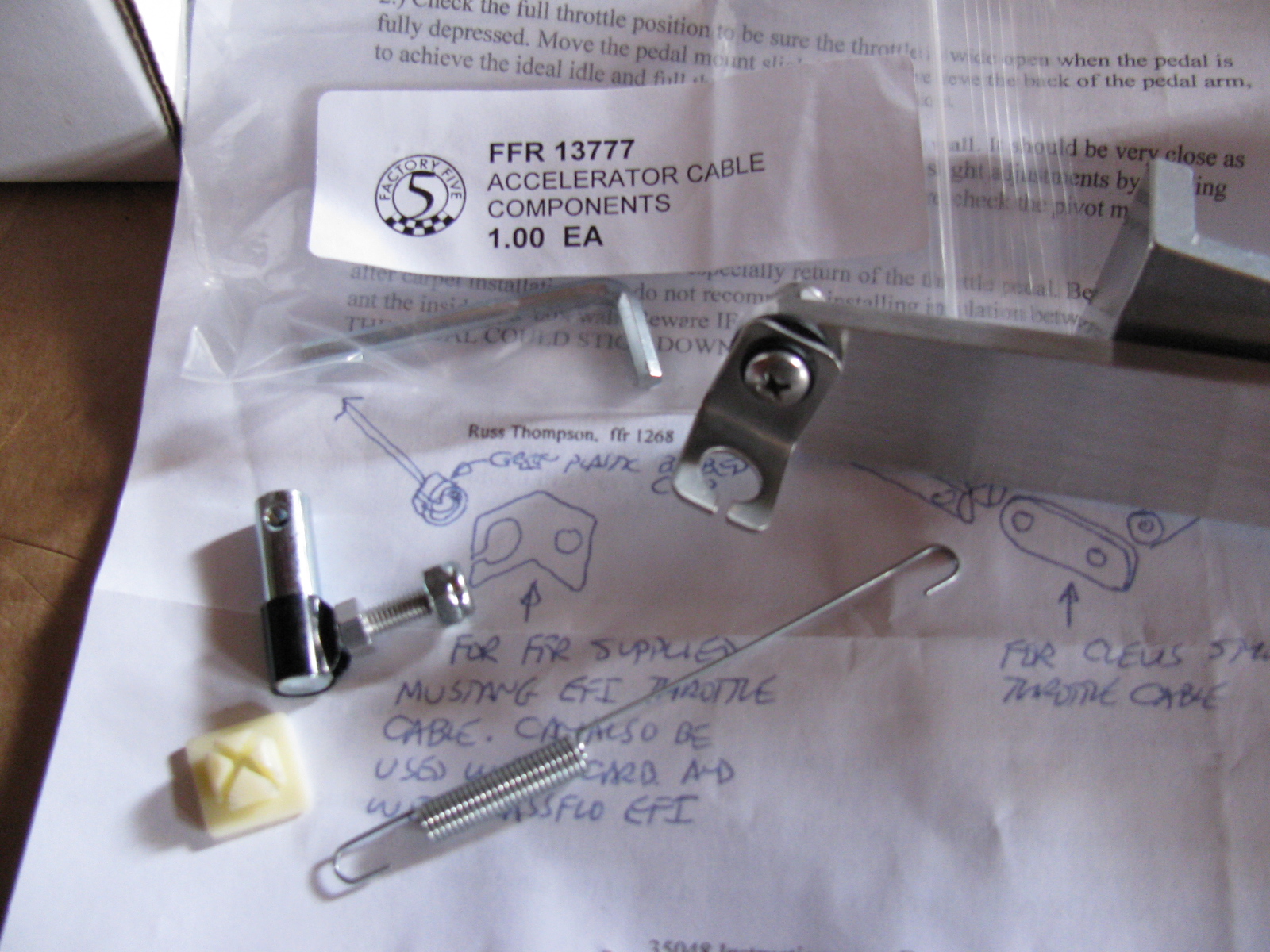
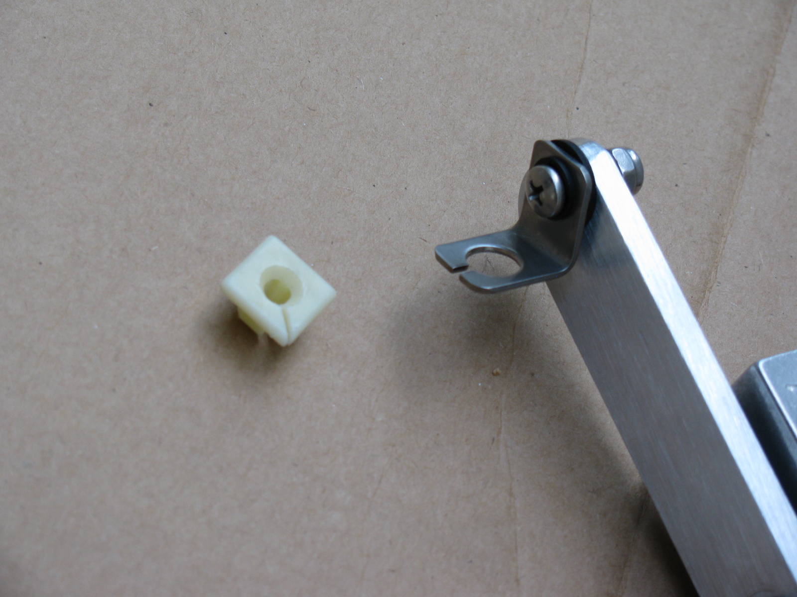
The picture above shows some of the gas pedal mounting parts that come with the Complete Kit. The Thompson / Breeze pedal instructions say something about a “green plastic barbed clip” at the end of the throttle cable. This green thing is no longer what comes with the kit. Instead, there is a little square “plug” that is too big to fit into the pedal mount.
Rather than cutting off the ball-end at the throttle cable or drill a bigger hole in the mount, I decided to carefully cut some of the plastic from the center barb so it would fit snugly into the mounting hole – not much has to be shaved off, it is something like a sixteenth of an inch or so. Then I made a slit in the square plastic thing as shown so the cable could slip in with the ball intact.
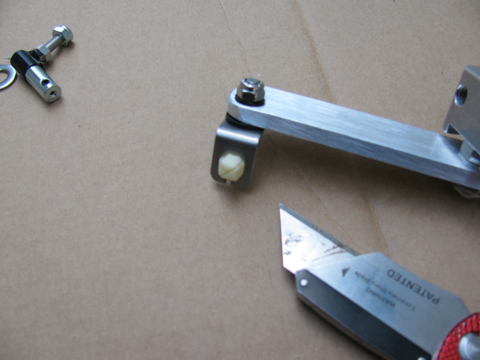

As you can see above, I added a fender washer (painted black) to the throttle cable mounting point, this is just for looks.
This is Irritating
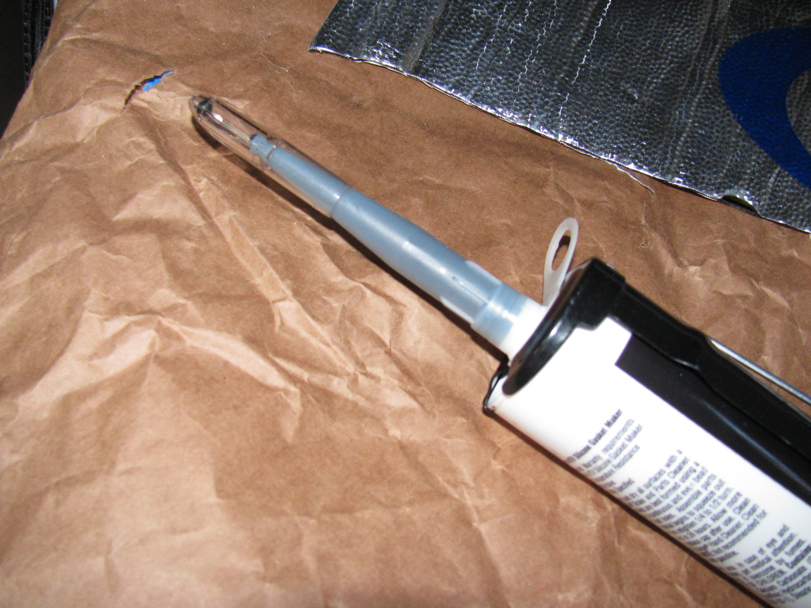
For some reason, this bothered me today, but then I realized not many tubes of caulk gun goop come with caps. Anyway, I used a pen cap to close the tube. I hope this works, I only needed a few beads for this build session.
Some Great Looking Door Panels on Order!
I ordered a set of leather door panels from Levy Racing earlier this week. They look like this:

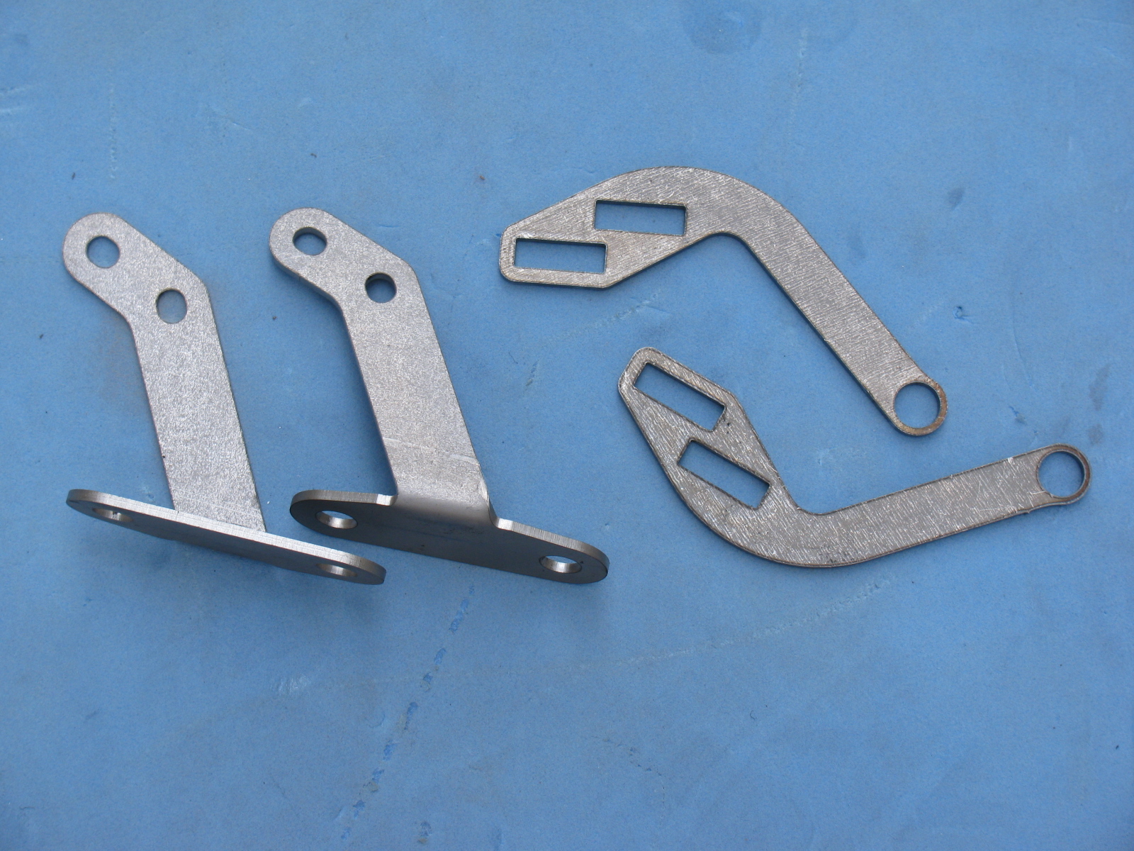
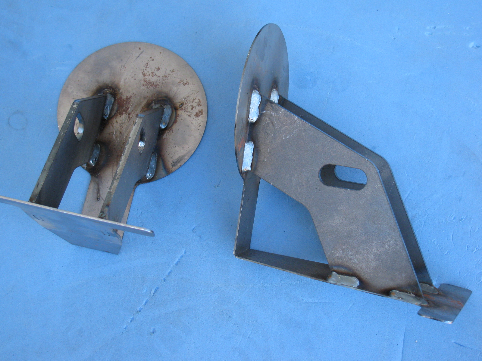
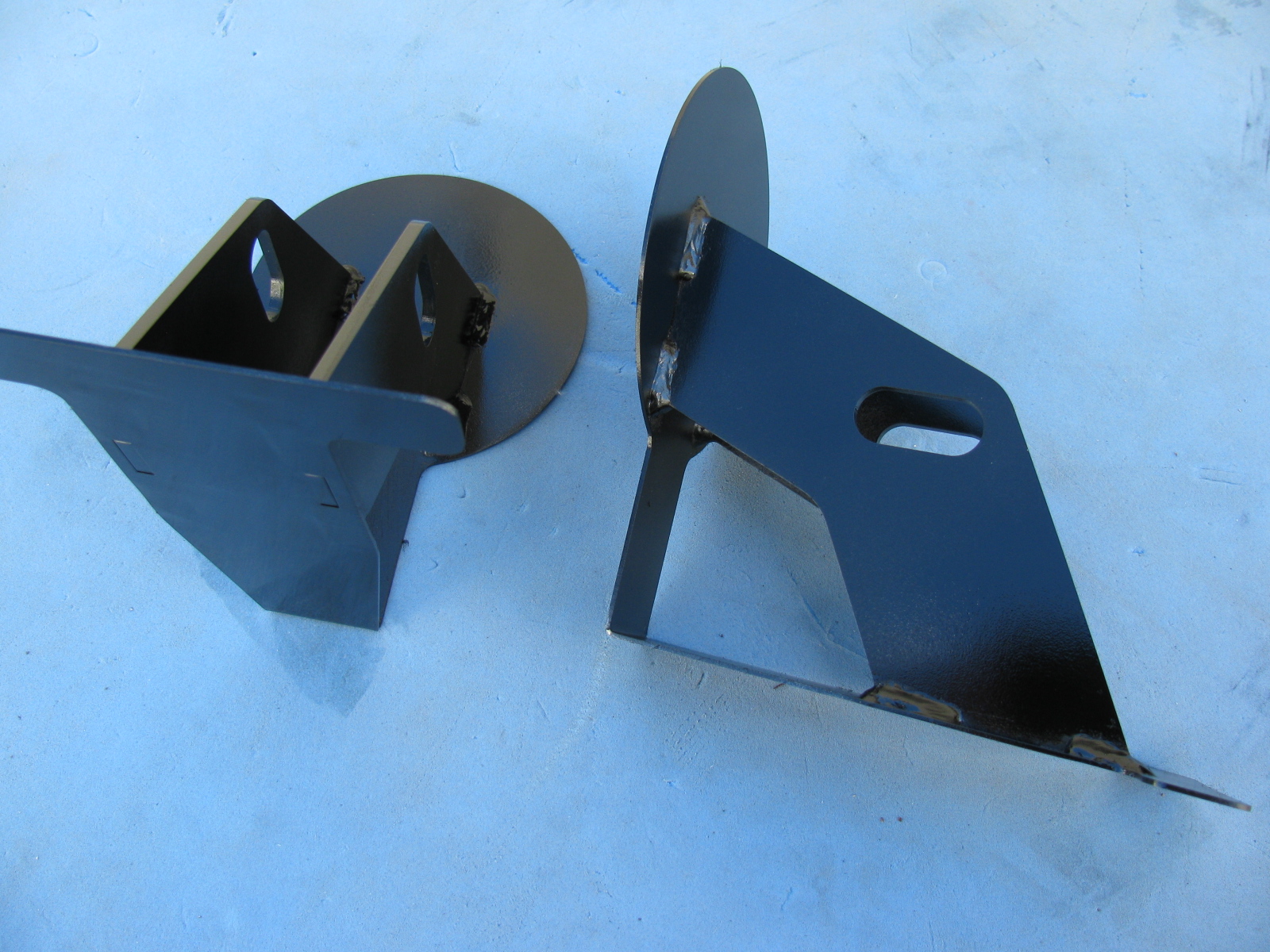
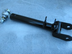
Not much Coupe time this weekend. The rear brake adapter plates and spacers from Factory Five Racing finally showed up – Saturday delivery via FedEx.

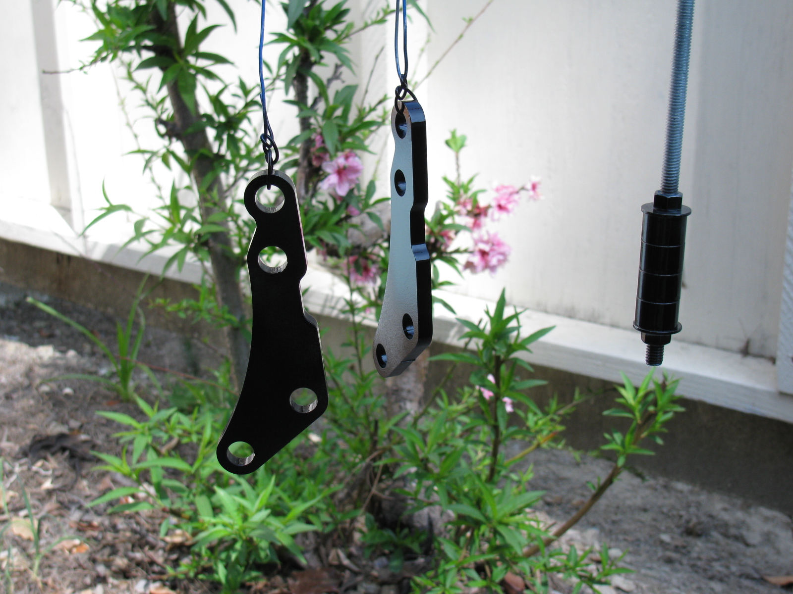
Since these are raw steel, I decided to prep and paint them, using gloss black Appliance Epoxy paint. They look much nicer now.
I removed the rear spindles from the last build session and did a dry-fit to see how these get assembled. Once again, the assembly manual and the actual assembly are different. Instructions say to use some button-head Allen bolts, but there aren’t any.
Here are some pictures of the “RH” side of the assembly to see how this goes together. The adapter plates are not painted in these images.
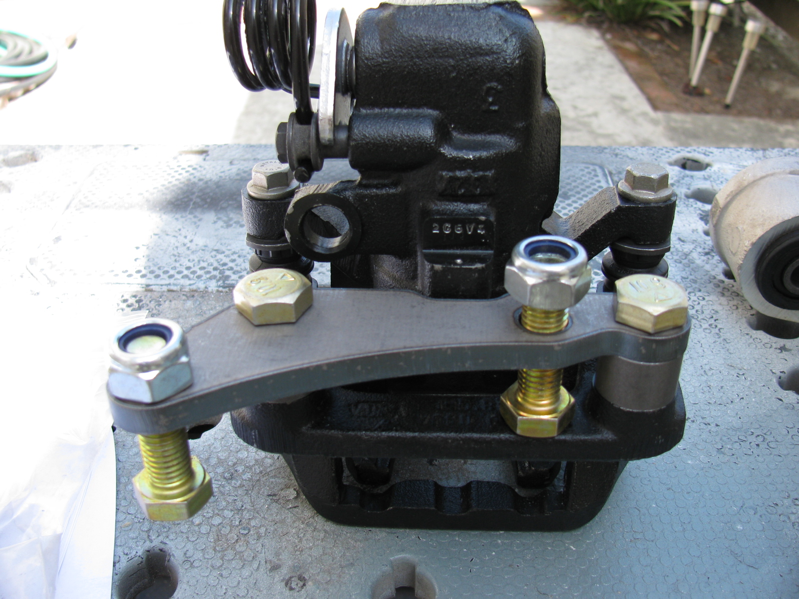
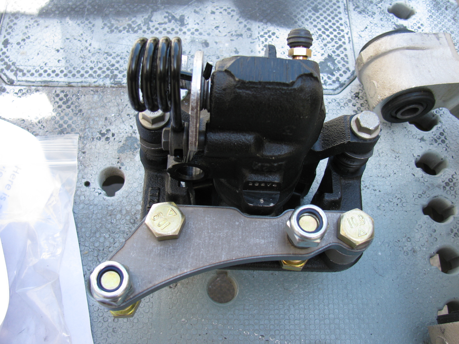


I will bolt these components in place in the next building session.
A Color Decision
I decided to paint the engine bay white. I know this sounds scary, but after thinking about this for a while, it just makes sense. It will match the body color, it will have nice contrast against the black chassis and the engine and other components, and – I can use Appliance Epoxy, which is pretty durable and washable. I will be painting only the outside surfaces of the panels because all of the inside surfaces will be covered with Thermo-Tec Cool-It sound and heat insulation mat.
I got tired of fiddling with the IRS so I did something different this weekend. Here is a picture of the E-brake ratchet handle that comes with the Complete Kit. Since the parts are plain, un-finished steel, I decided to paint it to prevent rust. The exploded view in the instructions make assembly very easy. I wish The Factory would include an exploded view for the IFS as well as the IRS – makes things go so much better. The finish is white and black appliance epoxy from Rustoleum.
Here are some pictures. . .


I am not sure if I like the location of the E-brake handle, it is on the passenger side of the transmission hump. A popular modification is to use a Pontiac Fiero unit and re-locate it closer to the driver. We’ll see if I want to change this setup. (The sharp-eyed people will notice the e-brake handle is backwards. . . . . . )
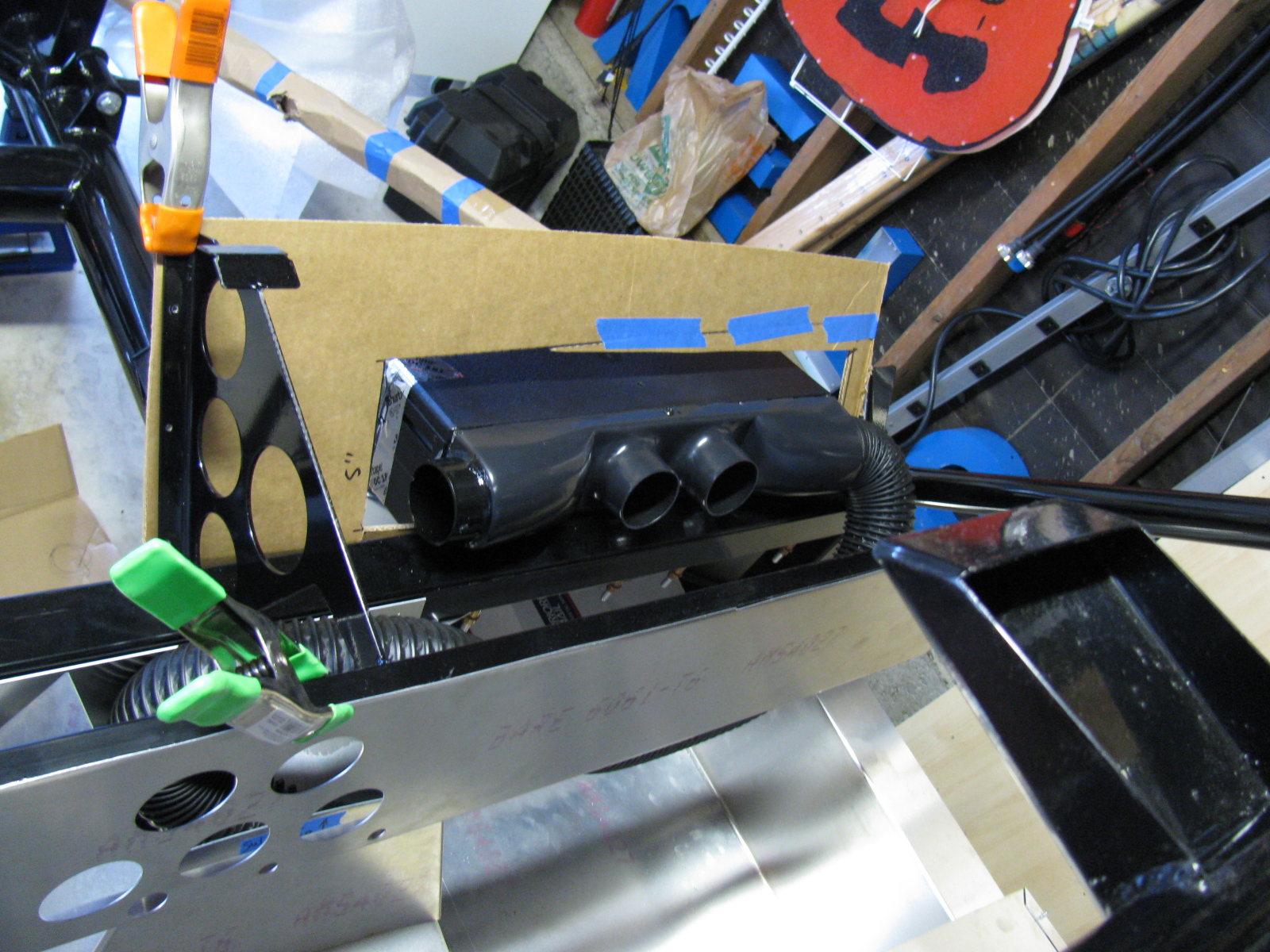
Here are some images of the air conditioner and a cardboard aided design (CAD) templates I am making. This requires some cutting of the dashboard and firewall, so I want to mock everything up before I start cutting. I have some very sturdy aluminium plates for the A/C baseplate, and some sheet aluminum for the enclosure. A CAD version will be made first, then transferred to aluminum.
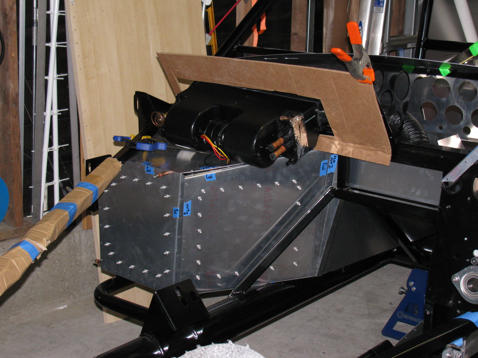


Moving back to the IRS, I received some advice from the veteran builders, and so here is what I did to the lower control arm mounts. The shims (thin black steel washers) F5R supplies are slipped into place and some adjustment is done by placing shims here and there. However, it makes more sense to limit the toe and camber adjusters so that the tweaking can be as simple as possible. By “fixing” one side of the control arm, and limiting it to one adjuster for toe and one adjuster for camber, alignment is simplified and less time consuming.
Currently, this stage is to just “eyeball” the adjustments, and continue the build process. Wheel alignments – both front and rear – may be done after the wheels and tires are mounted. (Probably can be done at the “go kart” stage, when the chassis is complete and the engine, drivetrain, electrics and brakes are installed and running.)
Here are some pictures. As this step gets closer to completion, I will add more details for future reference.


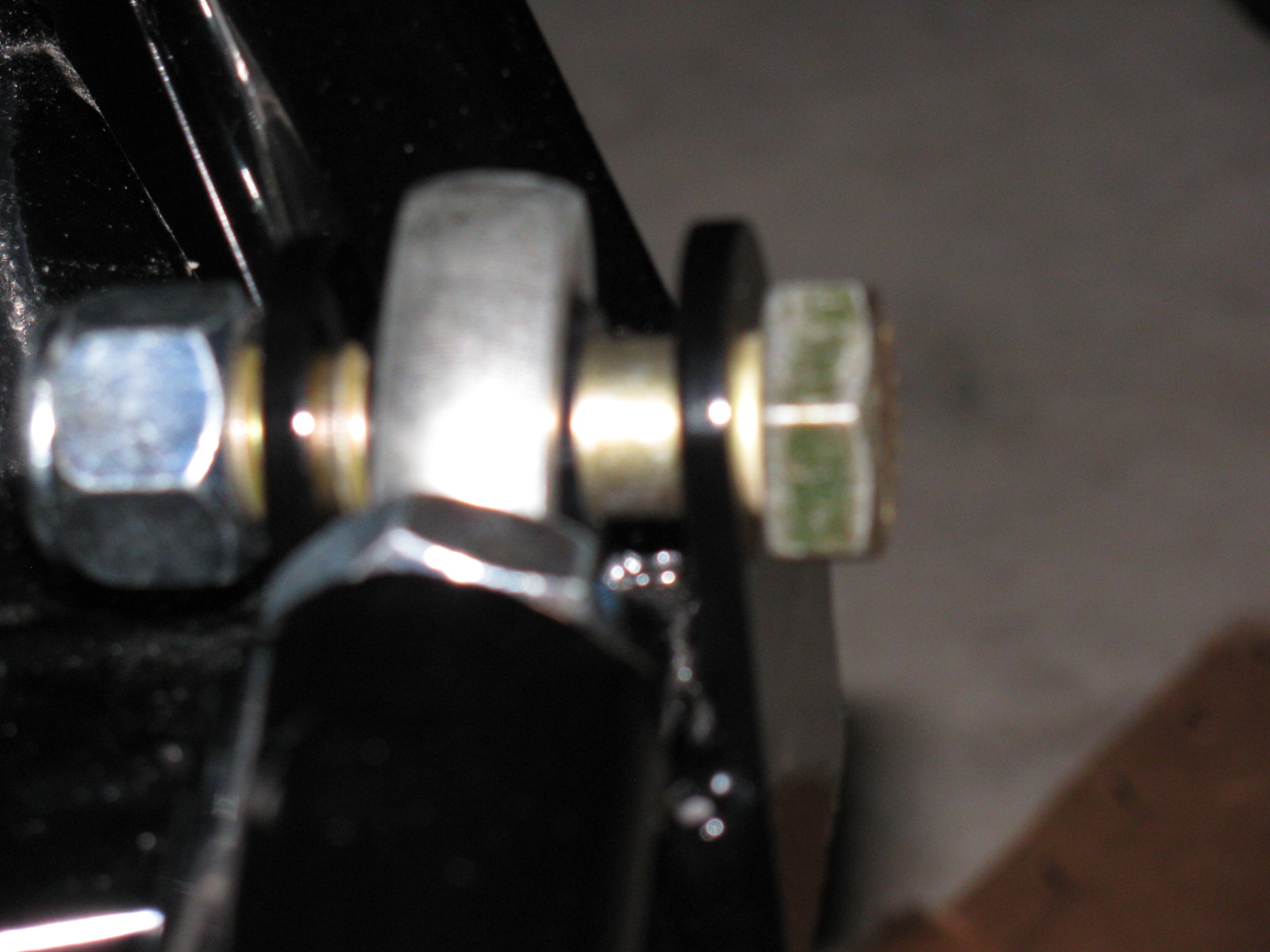
Above left: The Type 65 Coupe IRS lower control arm mounts. One shim on the front side of the mount, six shims on the side toward the rear of the car. The heim joint is threaded on so that 5/8-ths of an inch of thread are showing.
Above right: Here is the trick I use to install slippery washers, shims and spacers onto things – Use a punch or some other tool to poke through the stack of parts together, thus aligning the holes of each part. Then . . .

. . . push the fastener – and the punch – through the stack of parts. Wiggling, pushing and pulling will help. Sometimes a quick-clamp can help, too.
Maker Faire 2013 Update: Application is In!
I turned in an application for Maker Faire Bay Area 2013. Our Maker name is “Not Your Grandpa’s Ham Radio 2” and we will continue the theme my team entered last year. We will have some new projects on display, and we will bring some of the more popular items from last year. Here is a look at some of our projects from last year – as well as some other interesting and amazing things I saw last year.


Above – One of the most interesting exhibits at Maker Faire 2012 — The Electric Giraffe named Russell – it is a scaled-up and enhanced version of a plastic model kit – it is 17 feet tall. Below left: Jeri Ellsworth, aka Circuit Girl, and her electric Key-Tar at Maker Faire 2012. Below right, Maker Alex shows us her finger tip no keyboard keyboard.


More Maker Faire 2012 images are posted on my YouTube channel.
I did not do much work in the garage this past weekend, since I had to pull an all-nighter to get my CQ magazine article finished before a deadline, and there was a Coupe welcome party at a fellow Factory Five builder’s house.
Here are some pictures of a brand new Type 65 Coupe kit that recently arrived at QSL and Mrs QSL’s house. (They just finished a Factory Five Racing Roadster. It looks great and is finally registered and running.)
It was good to meet some of the other builders in the area and see the special parts QSL bought for MRS QSL’s Coupe.
Follow the Casey Family Coupe Thread for the latest updates on Mike and Julie’s Type 65 Coupe.


I took a nap shortly after I got home, lack of sleep from the all-night writing session before wore me out. I woke up, and it was dark outside, so I just went back to sleep, and woke up at 3AM on Sunday.
After doing some chores around the house, I decided to prep and paint the other steel parts on the Coupe. Here are some before and after pictures of the steel items painted with gloss black Rust-Oleum Appliance Epoxy. It is a great finish, and looks almost like black powder coat.

For some reason I didn’t take a picture of the hatch hinge parts or the door frame after painting. Oh well.
Hopefully will be able to get some more work done on the chassis and the rear suspension in particular next time.
Stay tuned for more. . . .
Some Body Parts, More IRS Conundrum and a New Microwave Antenna for KH6WZ
Inspired by a post on the Factory Five Racing forum and the dry and sunny weather this weekend, I decided to paint some of my body mounting parts. I am using gloss black Rust-Oleum Appliance Epoxy paint for these pieces. I have used this paint for my electronic and radio projects with good results. The paint dries very hard and is waterproof and washable, perfect for these parts.
Surface prep is easy for this paint, I scuff the surface with a 60 grit sanding disc on my random orbit sander. For the hard to reach nooks and crannies, I use a wire wheel chucked in my hand drill. Then I use liquid dish soap and water to wash off the grit and any oils. No primer is needed for this paint. Then I apply two or three light fog coats first, and then blast a thick coat for the fourth or fifth and final coat.
Here is a “before” and “after” picture of the front nose mounting hinge.
I did the same with the door hinges. Here you can see some weld splatter that will interfere with the mounting bolts, so I used a Dremel tool to grind those weld balls off.
Although many of these parts will not be seen, I do not want them to rust. Other parts will be painted in the same way, and include the door frames, the rear glass hatch hardware and the emergency brake mechanism.
Meanwhile . . .
After spending some time fiddling with the factory-supplied accelerator pedal, I decided to buy an aftermarket gas pedal instead. I ordered one of Russ Thompson’s gas pedals earlier this week from Breeze Automotive, one of the Factory Five Racing Forum supporters. I was amazed the box arrived on Thursday – that was fast!
The new gas pedal is really a machined aluminum sculpture. Pictures on this will be coming later, since I need to get the engine mounted before the gas pedal goes in.
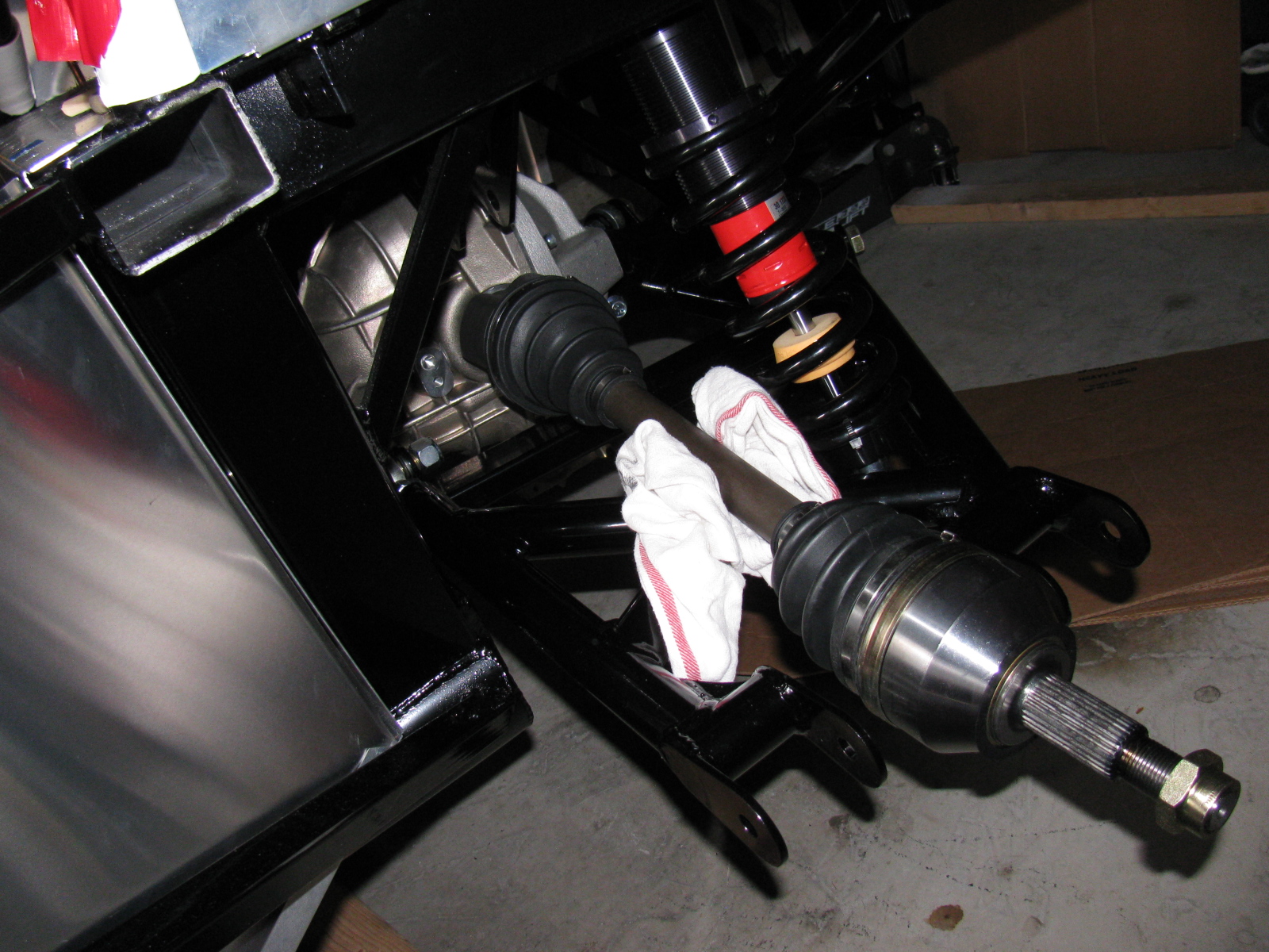
IRS – Finished – Sort Of . . .
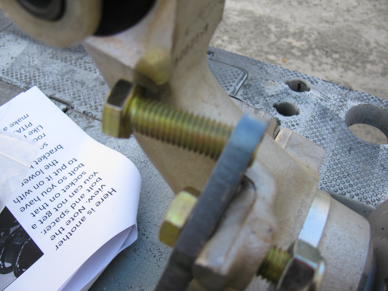
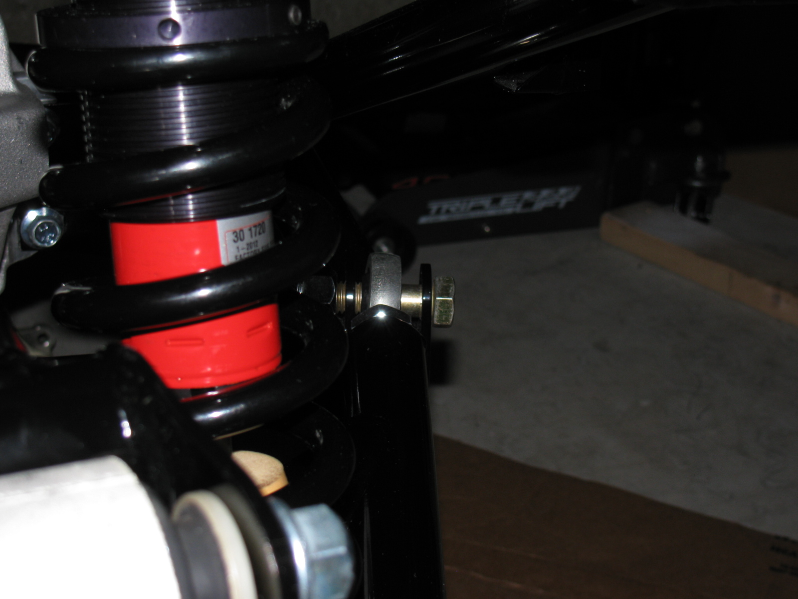
The IRS section is now fully “dry-fit” completed, and the bolts will be tightened to specs in the next work session. One thing that is putting this assembly step on hold are the mounting points for the lower control arms – see the gold color on the right of this picture? That is the mounting bolt and as you can see, there is a lot of empty space between the mounting ear and the thin washer (the manual calls them shims). This cannot be correct, and I need to find what is wrong here. . . .
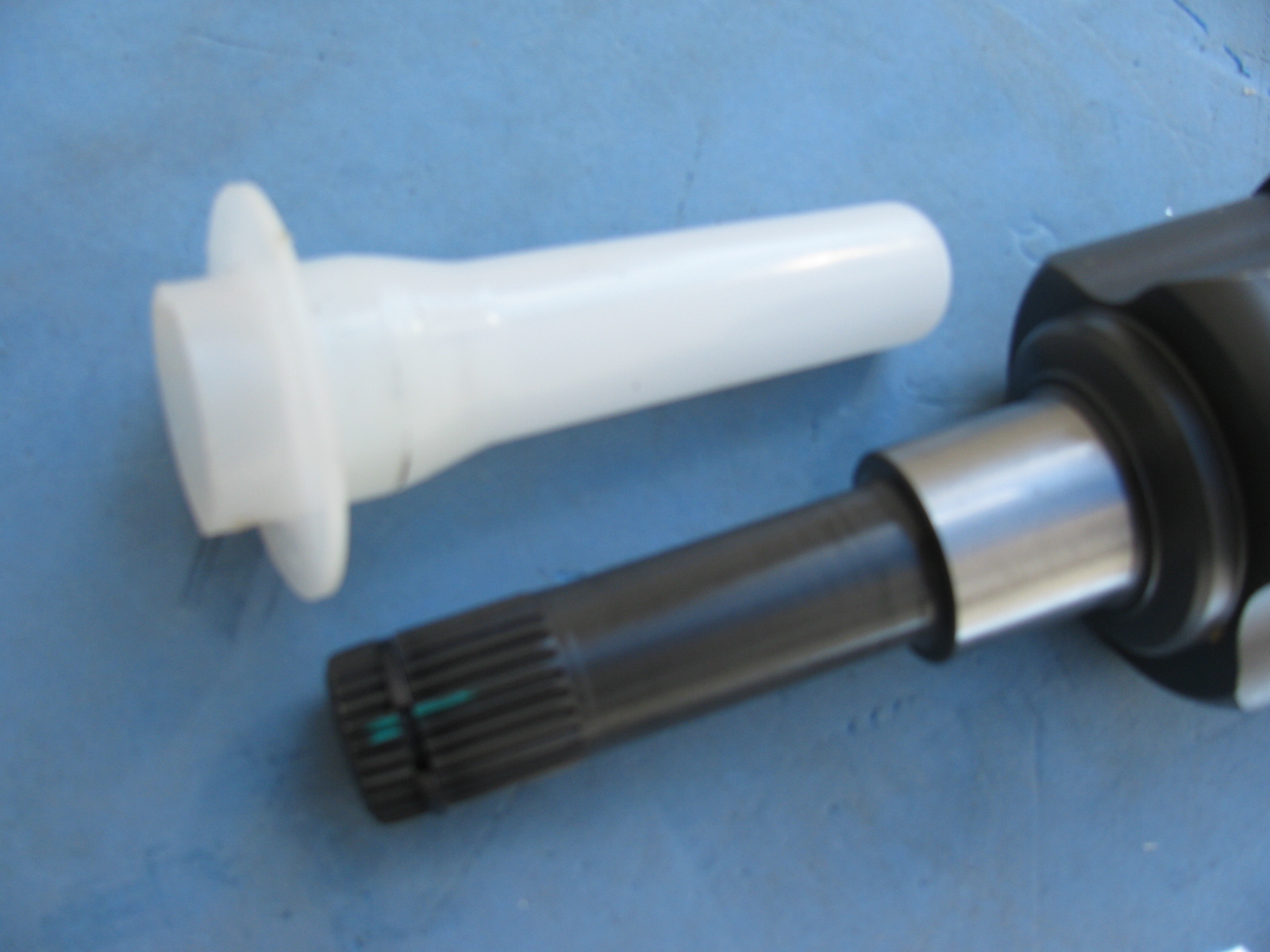
Just after I ordered my Type 65 Coupe kit, I came across a lot of posts on the forums about the IRS shafts (CV joints) coming apart. Those messages made me worry, but when my kit was shipped, the CV axles were on back-order. I called Factory Five Racing technical support, and they assured me that the problem has been fixed.
I am happy to report that my IRS system assembly went very smoothly, after the pumpkin was in place. The CV axles slipped right into the differential, and it felt just like many posts said – you can feel it lock into place. No hammering, no drama and no R- and X-rated words necessary.
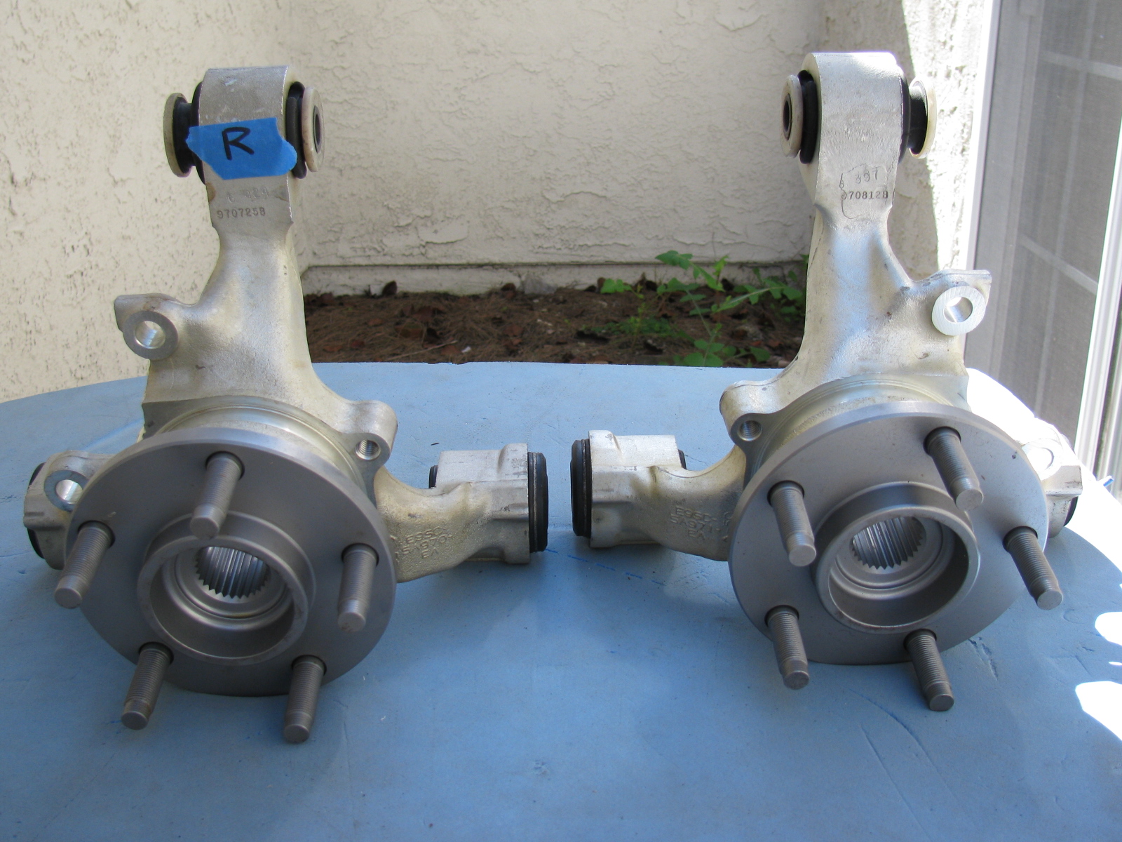
Once again, Chris comes to the rescue by posting images of the IRS knuckles and which part goes on the left side and which one goes on the right side.
Here are some additional pictures of the IRS components and system . . . . “R” is for Right side of vehicle (passenger side in the US)
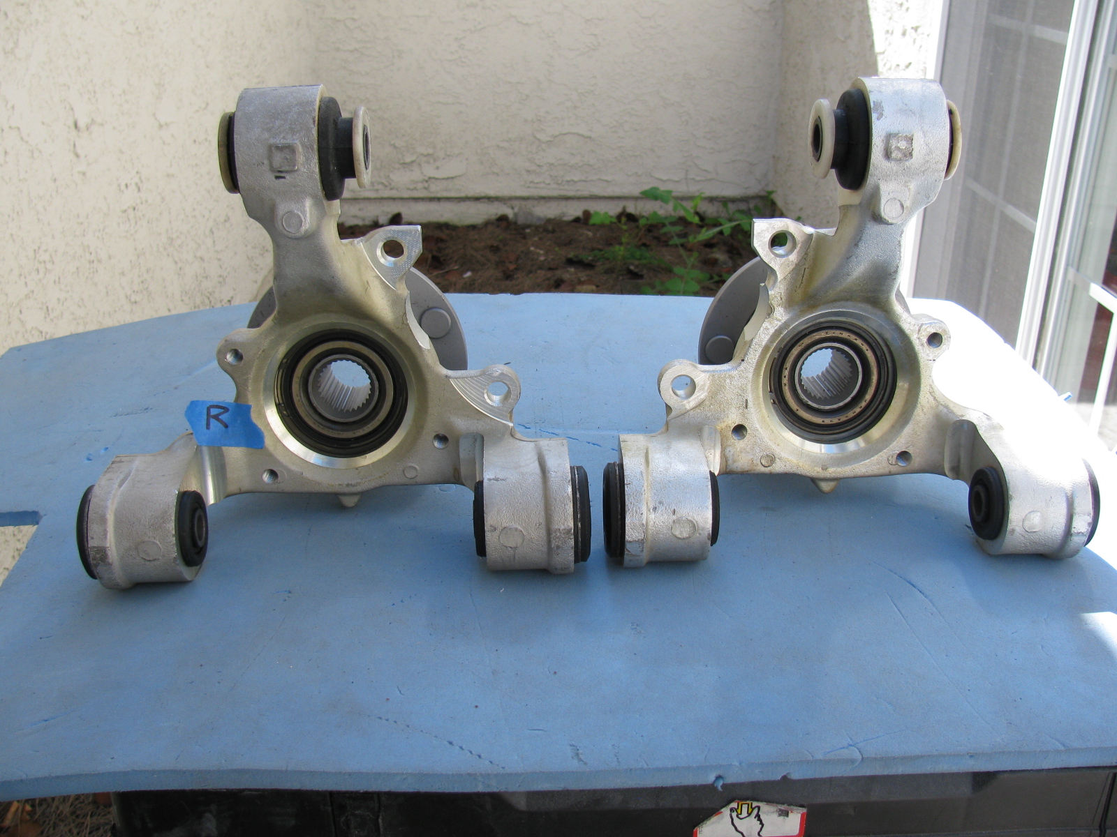
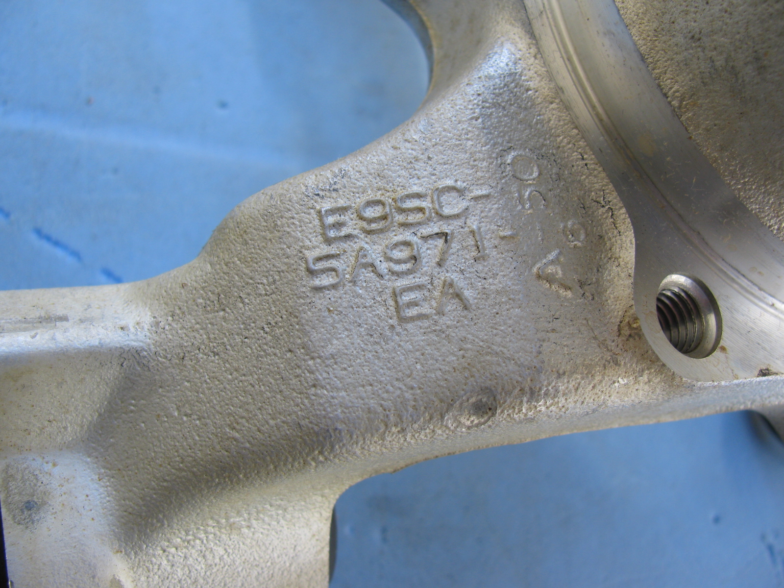


Above left: The IRS upper control arm has another pair of small mounting tabs that are not mentioned in the assembly manual. No pictures are included in the manual, either. After a quick search on the Factory Five forum, I found out the smaller set of tabs point downward, and are used for quad shocks – used to minimize wheel hop during acceleration.
Give Me a Brake – Again
Now, the rear brakes are another story. Seems the Factory sent me the wrong rear brake kit. So now I have to wait for the correct parts to arrive, and then have to send the wrong parts back. . . Stay tuned for more . . .
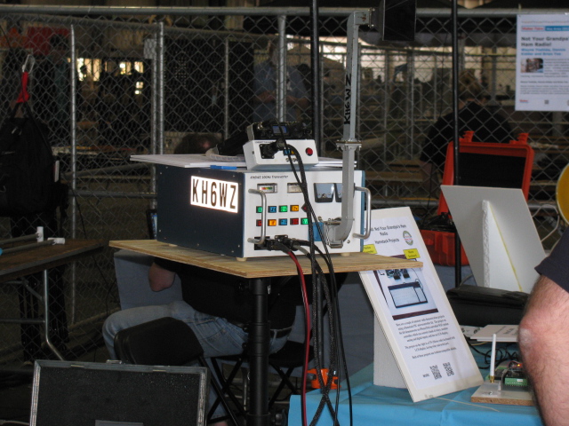
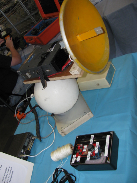
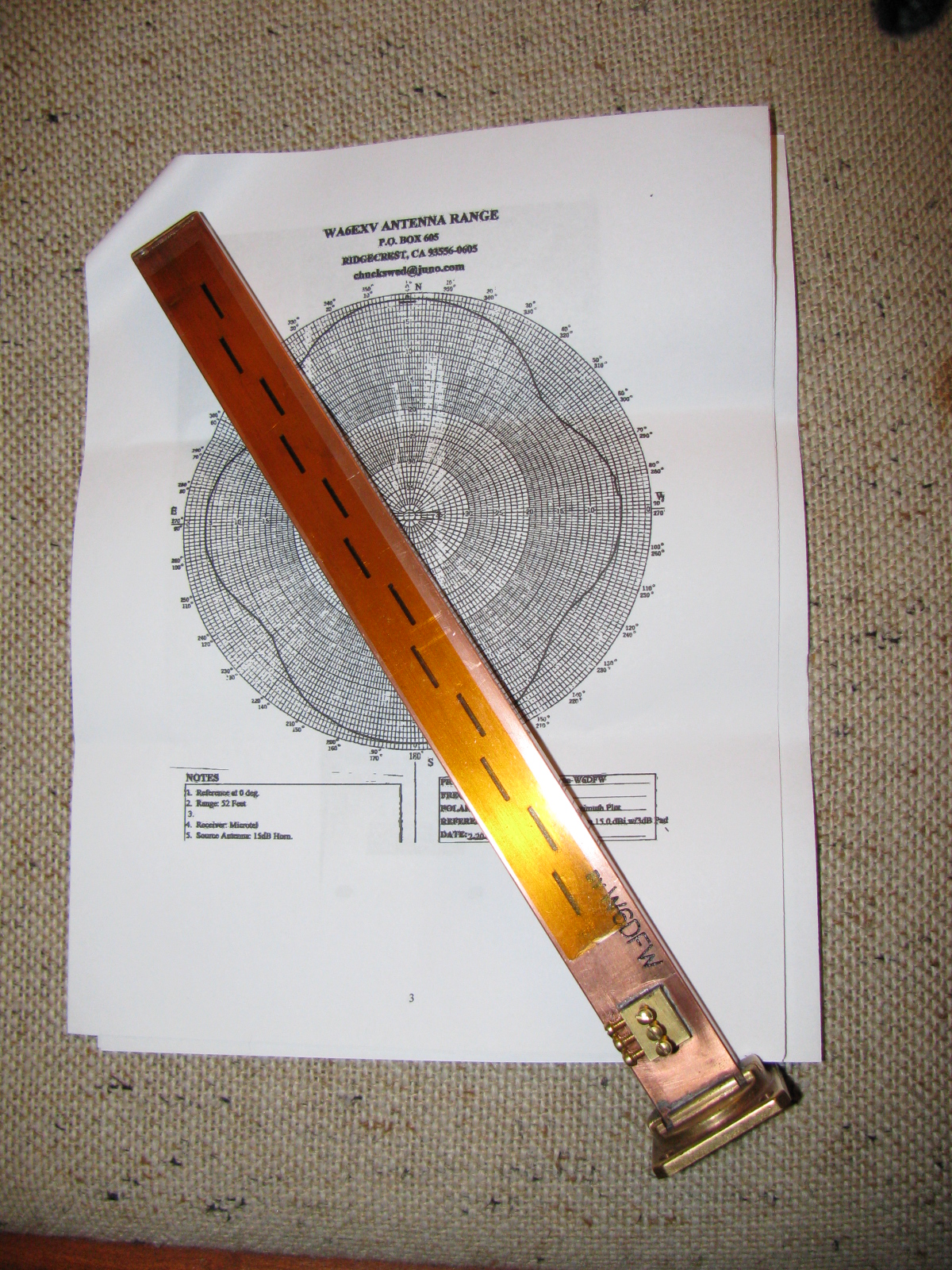
Another Box Arrived this Week – a 10 GHz Slot Antenna
I received this nicely machined antenna for 10 GHz earlier this week. It is made by fellow SBMS member Dan, W6DFW.
Here’s a picture of this omni-directional microwave antenna. The background is the radiation pattern plotted by another SBMS member, Chuck, WA6EXV.
I am planning on using this to make my roving 10 GHz station even more portable, perhaps getting on 10 GHz FM mobile. More on this item and possible applications at station KH6WZ later.
Since the engine is in the middle of my garage, I really need to accelerate my building, or at least, get my chassis ready for engine installation.
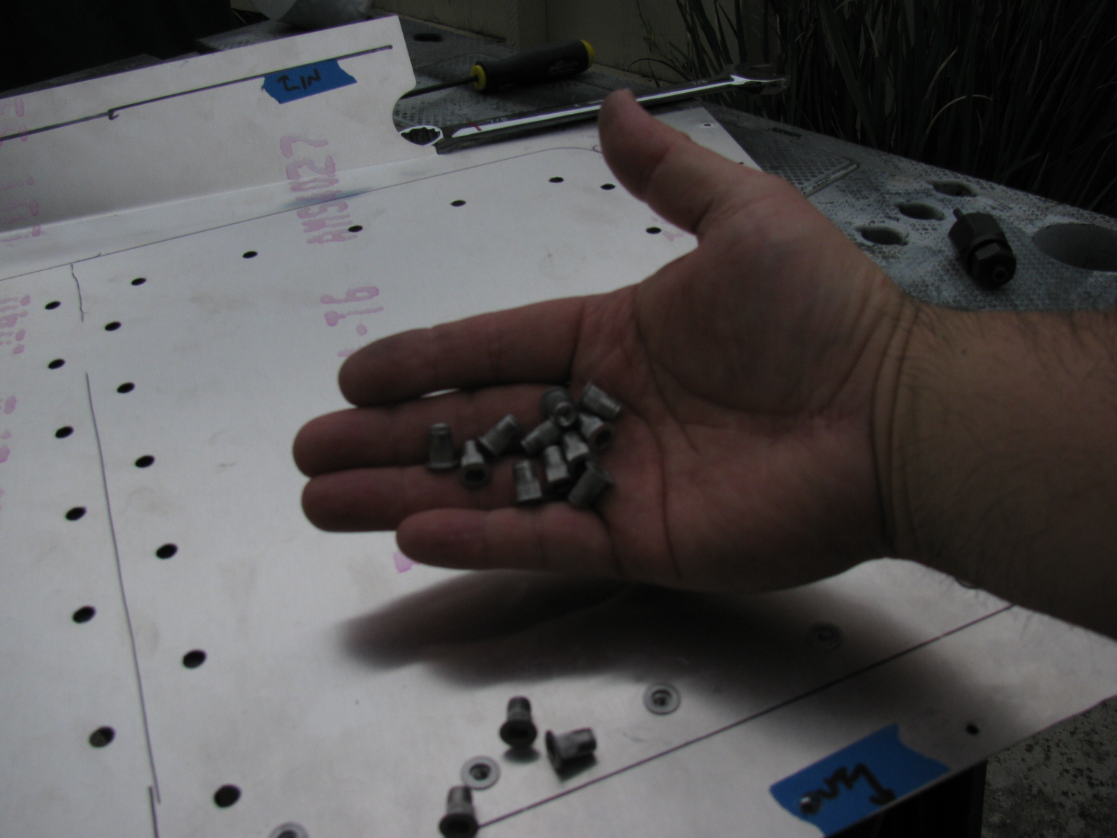
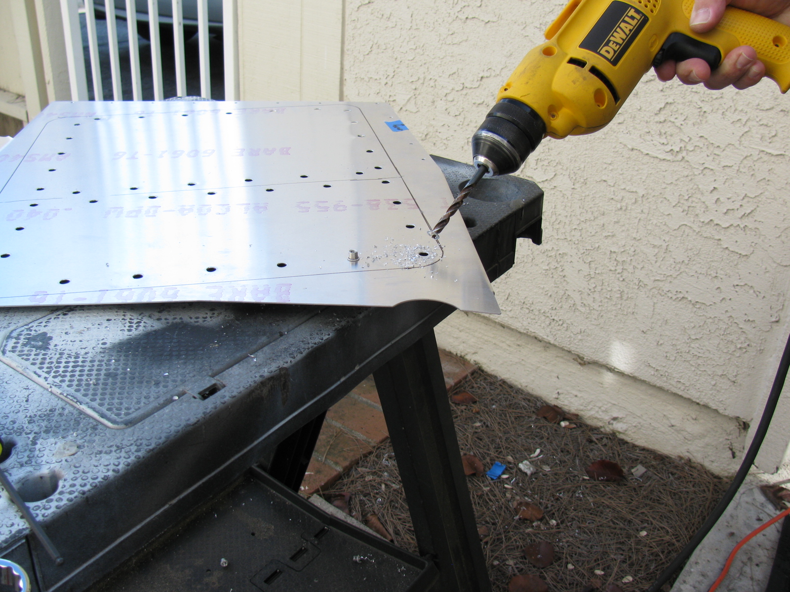
I looked at my cookie sheet heat shields and the mounting locations filled with 8-32 riv-nuts, and thought – shoot, the riv-nuts actually have a shaft that might be used as stand-offs for the shield plates. So I checked the length, and the threaded shafts are about a quarter-inch long, enough to be used as a spacer between the firewall and the heat shield. I may add another quarter-inch in certain places, if there is room.
So I spent a few hours removing all of the riv-nuts I installed a few weeks ago. Good thing I bought several hundred from McMaster-Carr. . . .
At least I am an expert on installing and extracting riv-nuts now.
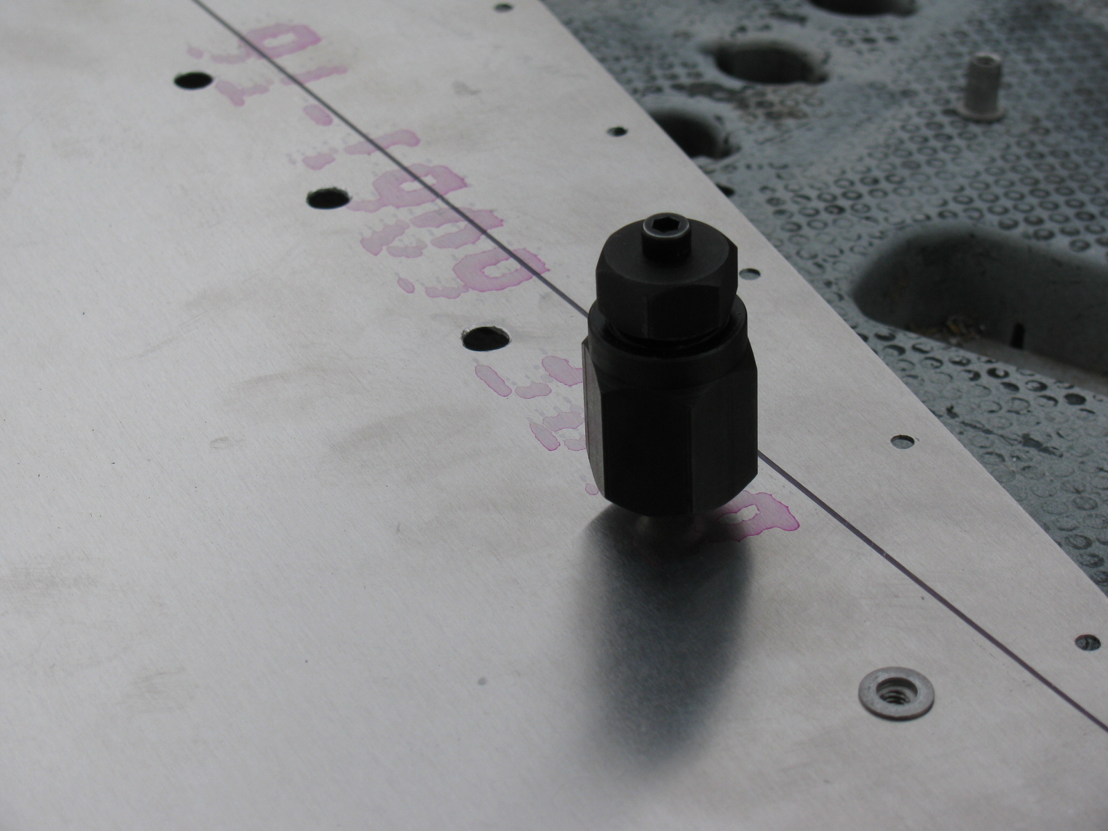
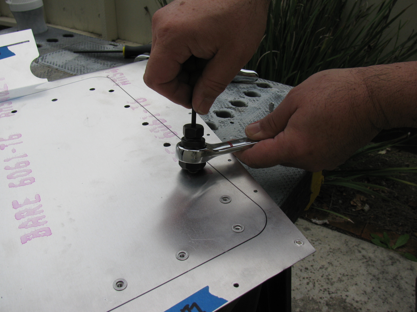
Rivet Nuts and the Rivet Nut Tool
Here are some pictures of the riv-nut tool from McMaster-Carr and how it is used. Riv-nut fasteners are very handy if you need a threaded hole installed into a blind location, or when you do not have access to the back side of a mounting surface. I will use these fasteners for hatches and compartments in the trunk area of the Type 65 Coupe.
McMaster-Carr information
Wrench-drive rivet nut installation tool for 10-24 and 10-32 thread: 96349A203
Wrench-drive rivet nut installation tool for 8-32 thread: 96349A152
Wrench-drive rivet nut installation tool for 6-32 thread: 96349A101
Aluminum heavy-duty rivet nut, 6-32 internal thread, .080″-.130″ material thickness, packs of 25: 94020A315
Aluminum heavy-duty rivet nut, 8-32 internal thread, .080″-.130″ material thickness, packs of 25: 94020A323
Aluminum heavy-duty rivet nut, 8-32 internal thread, .020″-.080″ material thickness, packs of 25: 94020A319

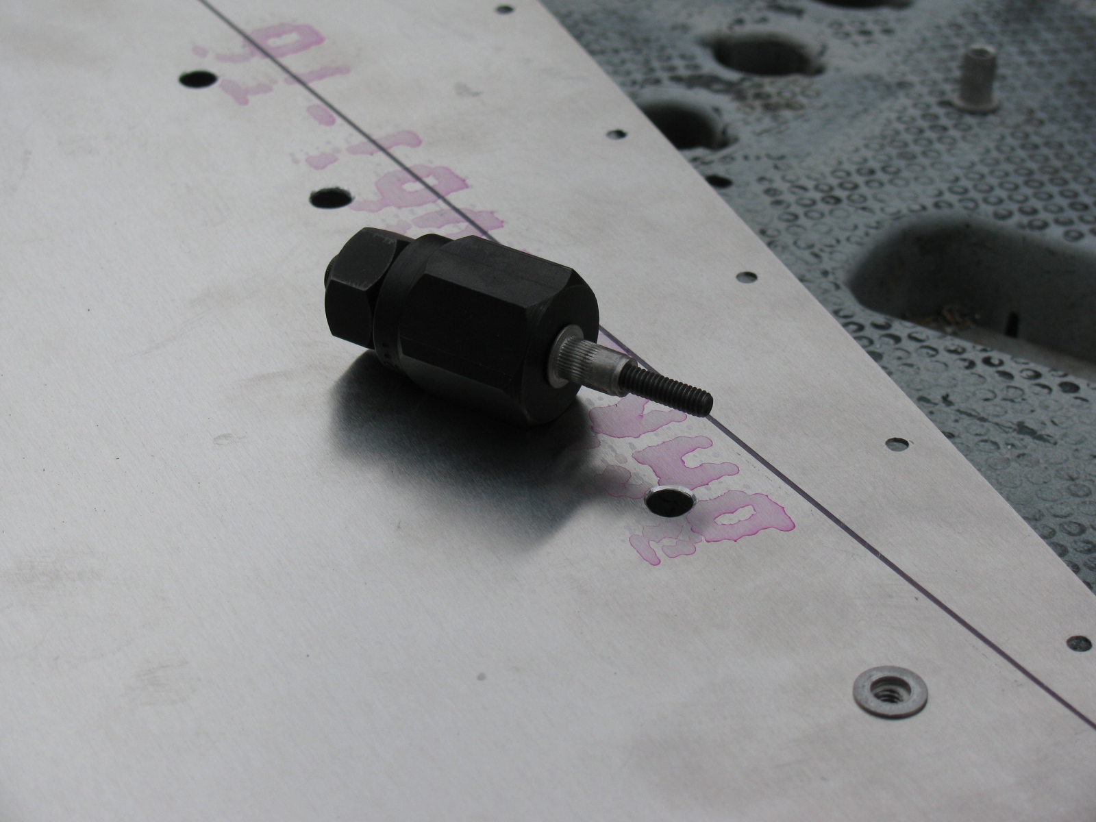

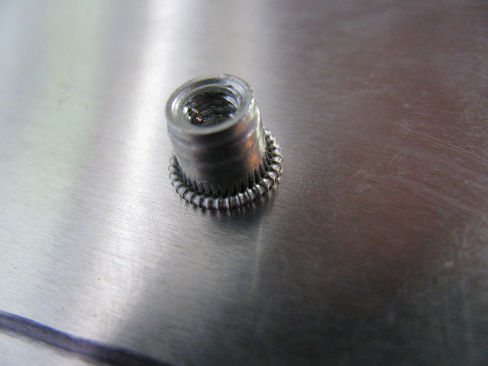

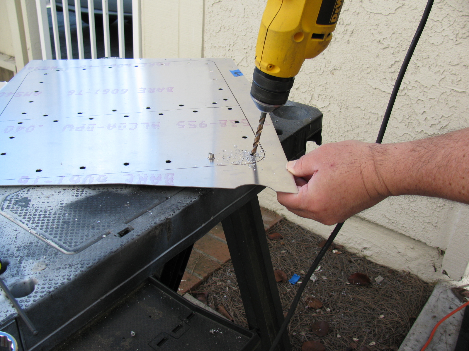
Above left – a picture of a properly installed riv-nut, viewed from the reverse (back) side. At right, a riv-nut improperly installed, viewed from the face (front) side. This one must be removed by drilling the riv-nut out. Below left, use a twist drill slightly smaller than the mounting hole, in this case, a 1/4-inch bit is being used to drill out the riv-nut. By slightly rocking the drill, the riv-nut will break apart and, usually, just fall out of its hole.
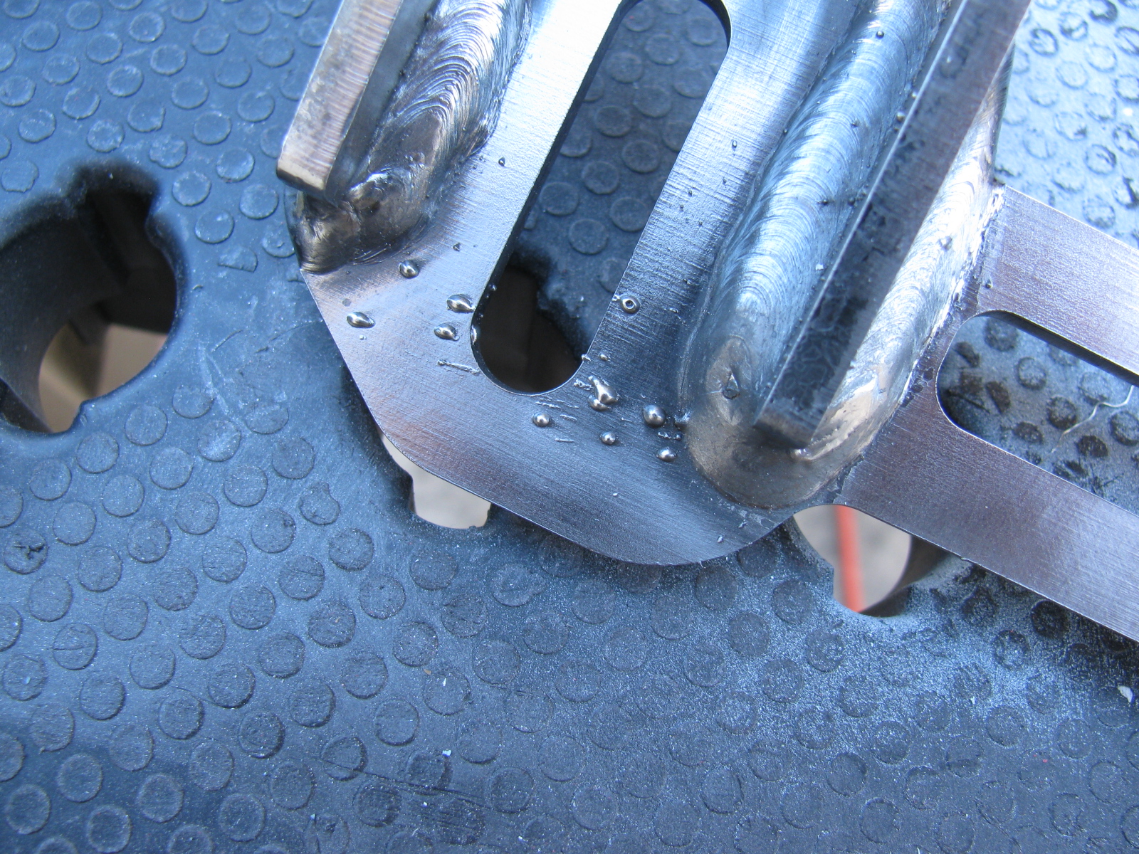
Give Me a Brake: The Wilwood Pedal Box
The pedal box is a challenge to install with the Factory Five Racing Assembly Manual, revision 3E, July 2011 – since there are no assembly instructions for the Wilwood Complete Kit pedal box.
Fortunately, a dedicated Type 65 Coupe builder named Chris has an excellent photo album of his Coupe build, with many detailed images. Without his documentation – it would have been impossible to assemble this part of the kit. Take a look at cbergquist1’s photostream on Flickr.
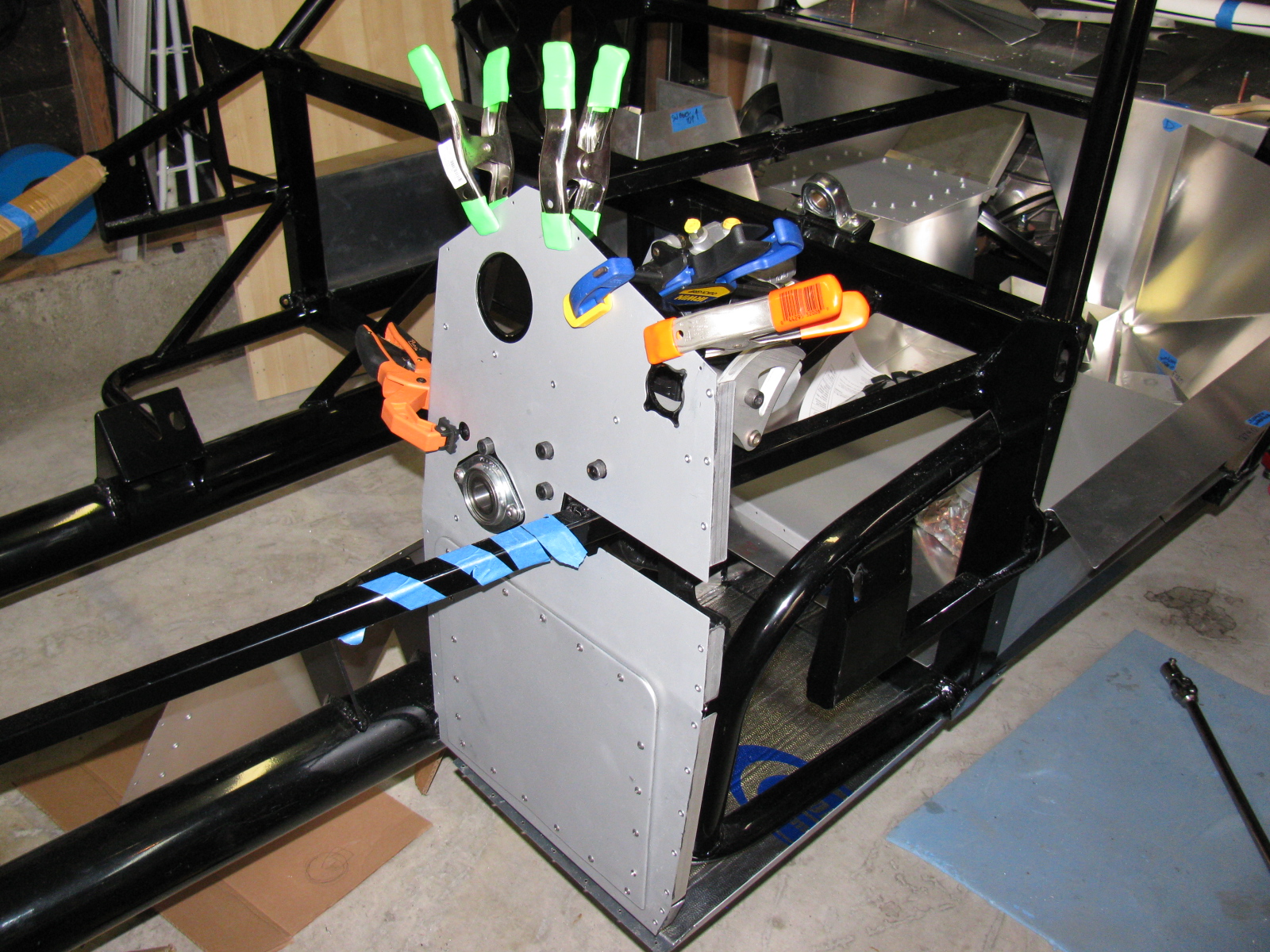
Here are some pictures of my pedal box, including a trouble spot I ran into, and how I had to fix it. . . .

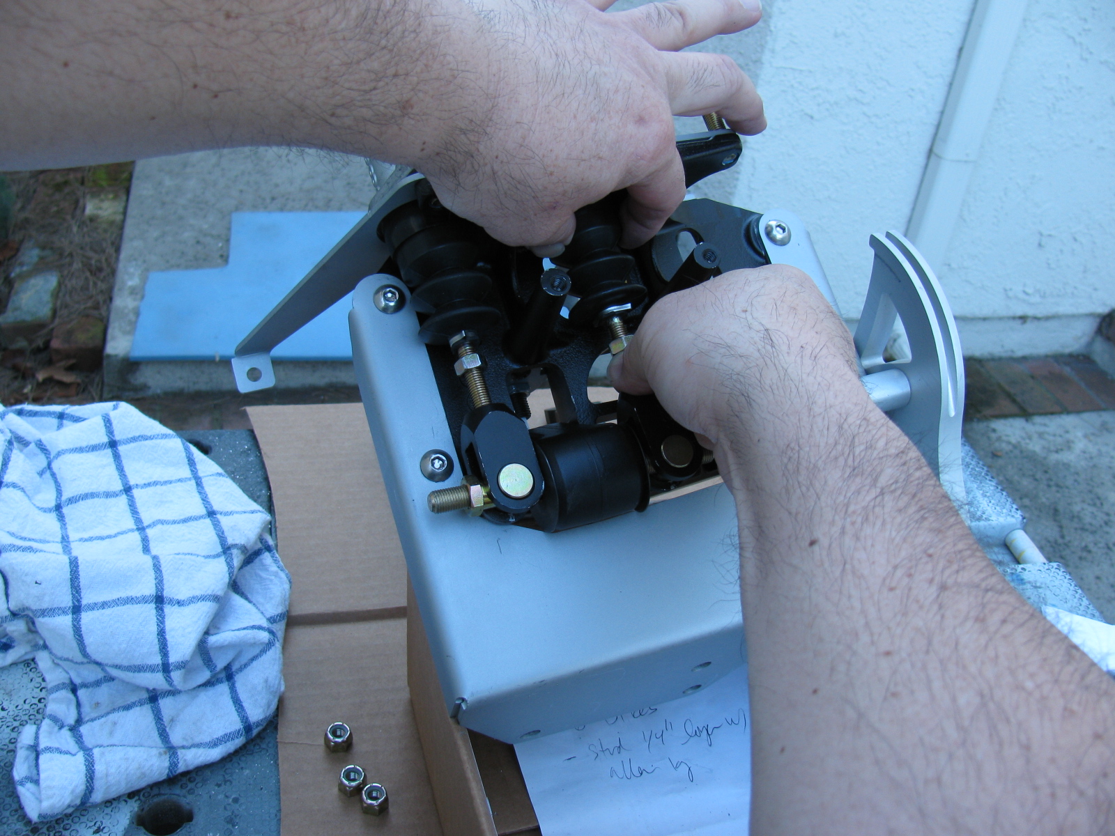
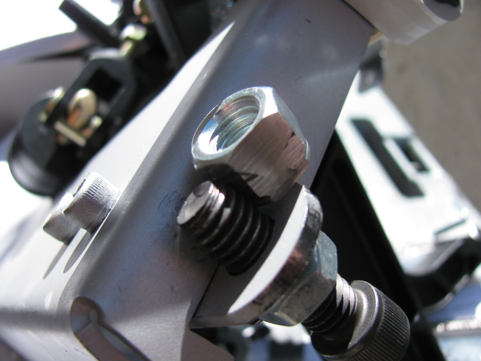
This is the clutch quadrant adjuster (above). This Nylok had to be ground down to fit properly. The hole in the adjuster plate is too close to the master cylinder mounting plate. A better solution would be to eliminate the Nylok altogether and thread the small plate. Then the lock nut and Allen bolt are used to make clutch travel adjustments.
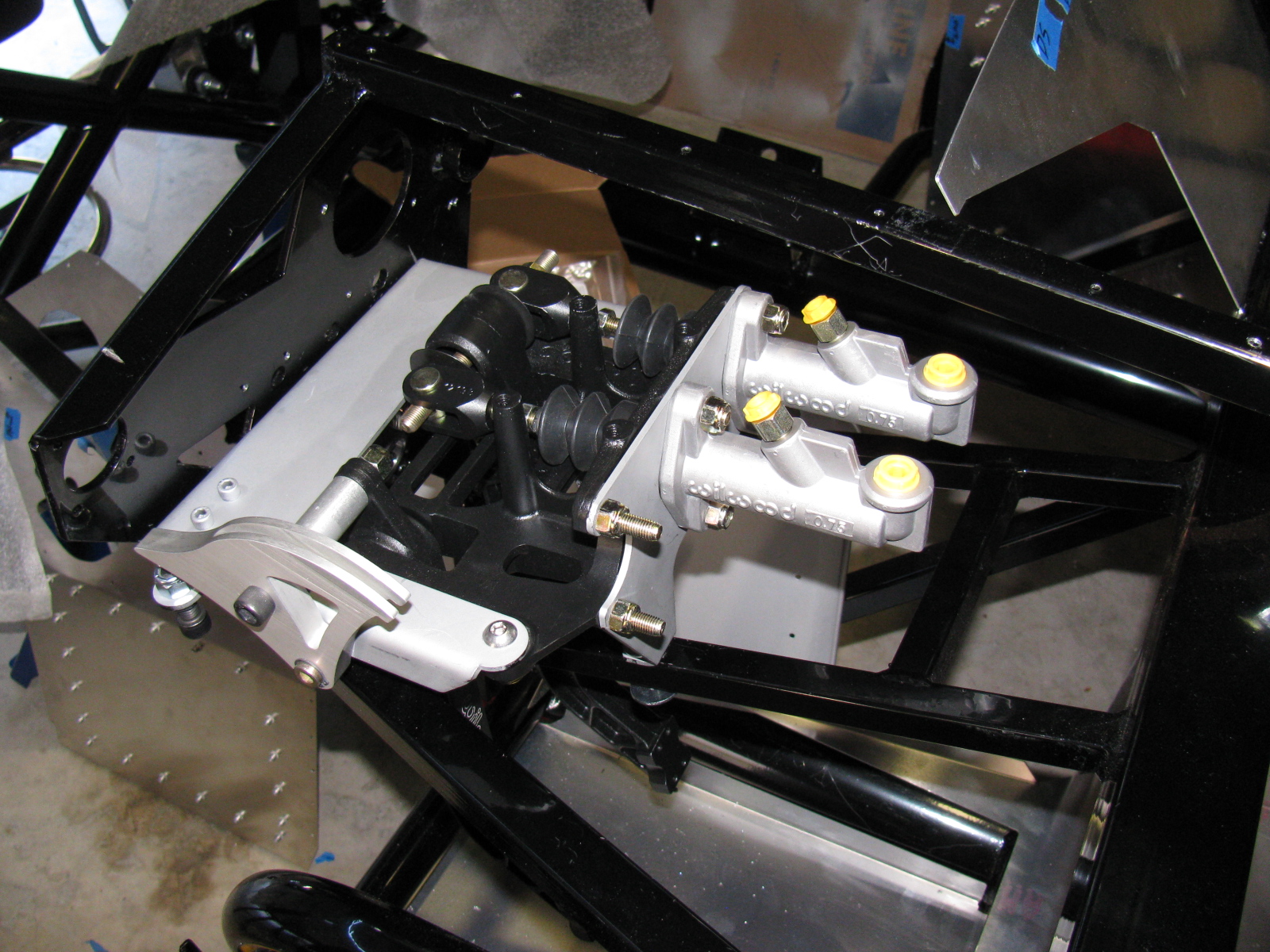

Now I have to find a place to mount the master cylinder reservoir. There are some rare posts about this, but most of them are for the Factory Five Racing Roadster.
I think I will mount mine at or near the peak of the driver’s side footbox/firewall. This location should be away from too much heat, and should be in the clear for fluid bleeding, checks and re-filling. We will see. . .
The Gas Pedal

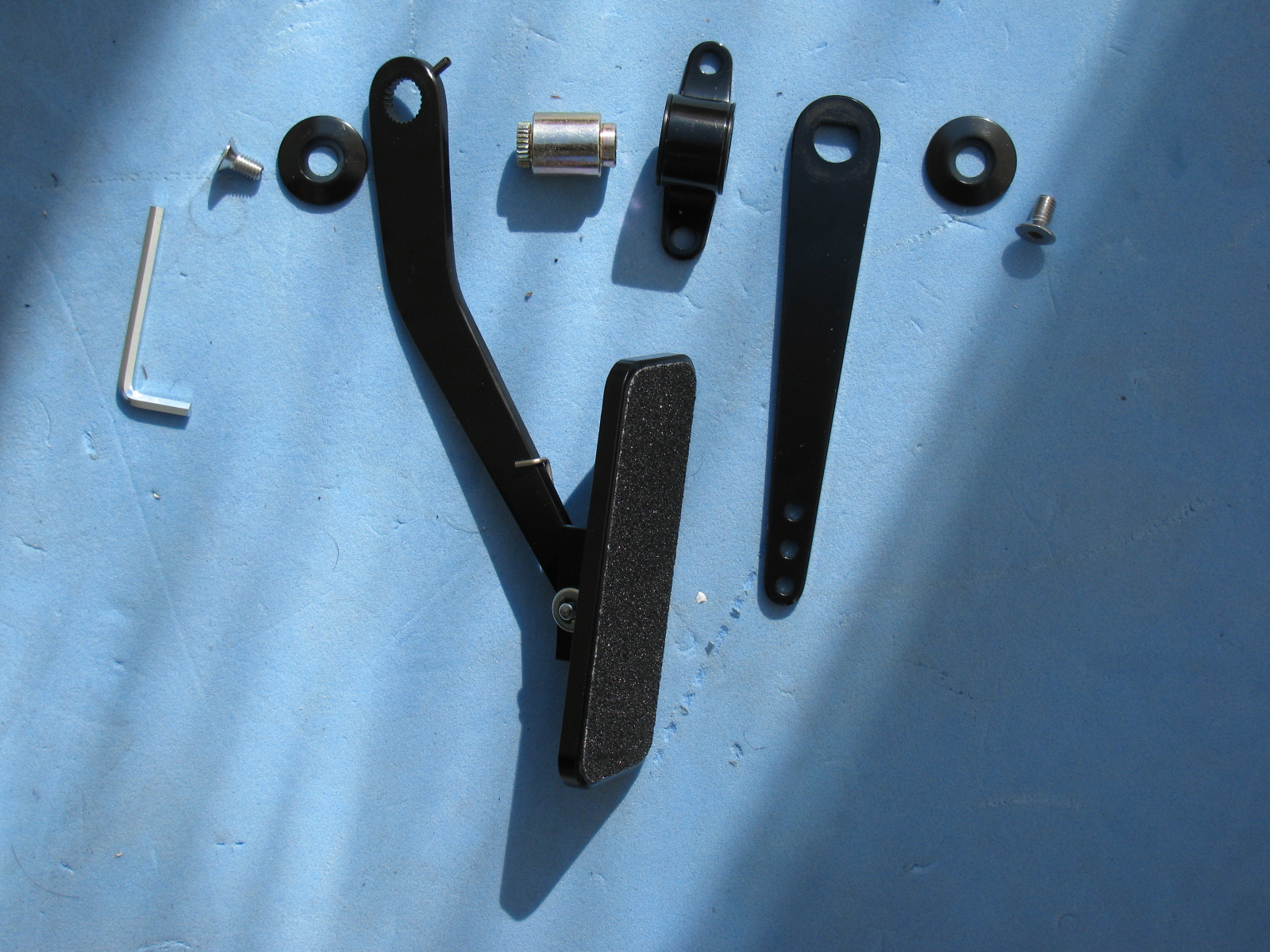
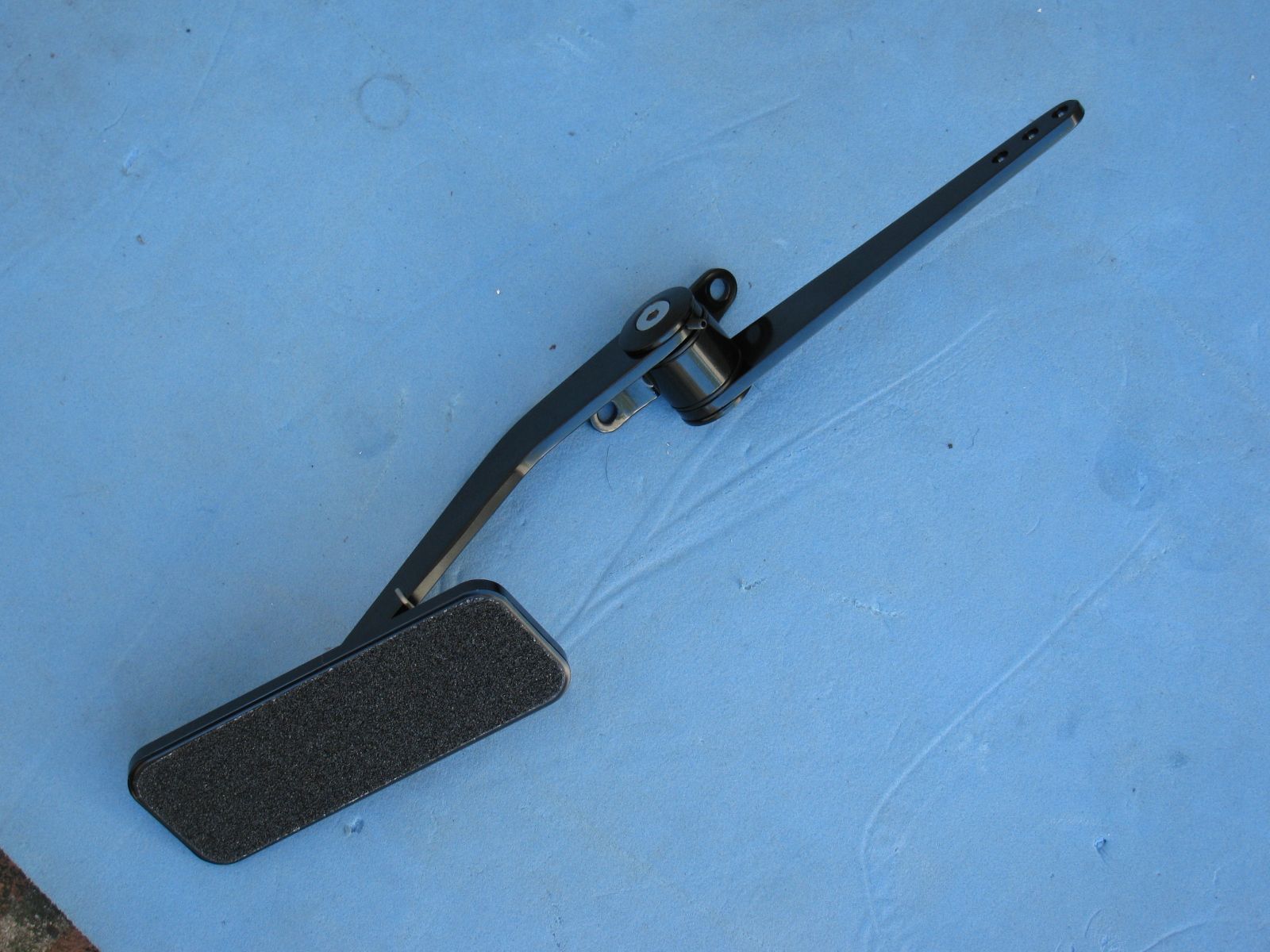


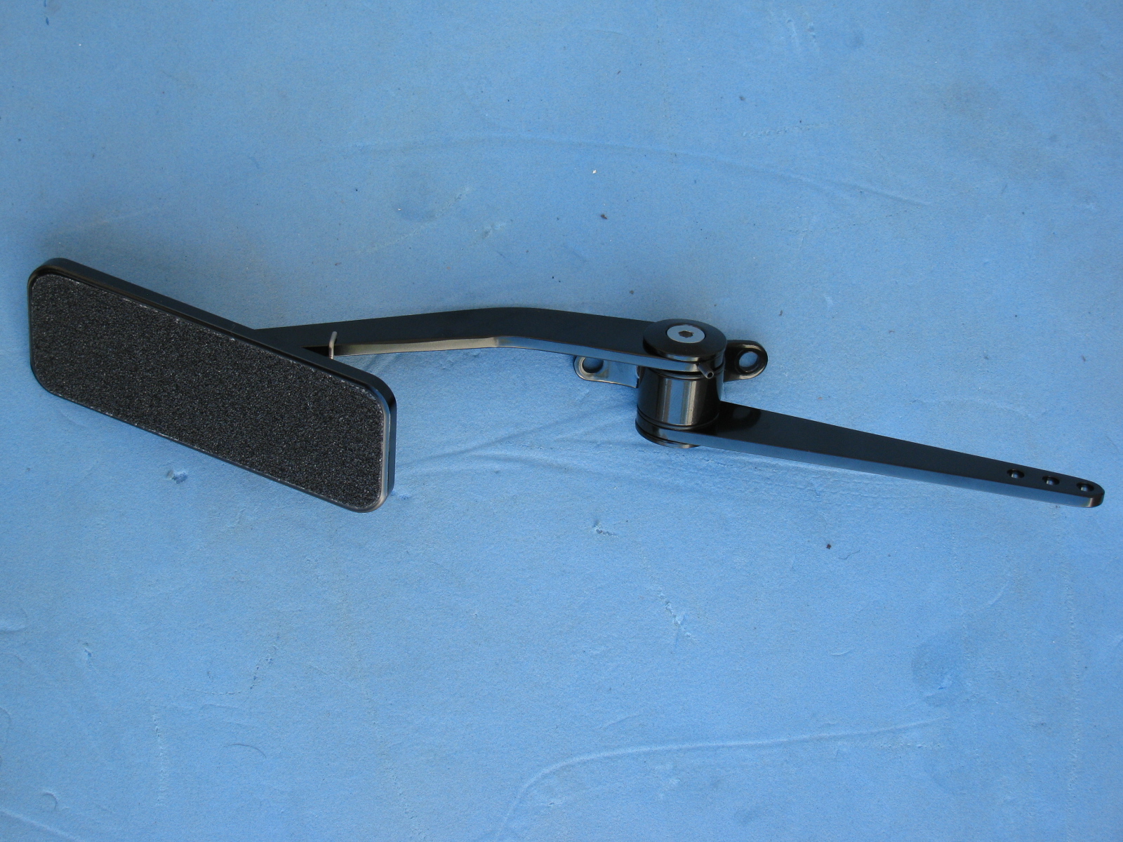
Part of the pedal box area is the accelerator pedal. Again, instructions are very skimpy on how to put this thing together. Here are some pictures of the gas pedal parts and how to dis-assemble the unit as it comes out of the box, and where it mounts onto the firewall area. Adjustments for the pedal box and accelerator pedal will happen later.
The Factory Five Racing Cruise-In at Huntington Beach is expanded to include both Pier Plaza and Main Street this year. On top of all this, a tour of the Riverside Auto Museum and an autocross event is scheduled for Sunday, April 28.
The event is free and open to the public, an entry fee is charged for Factory Five Racing car display space.
Click here for more information on the 2013 event.
Click here for a quick video of last year’s Moment of Thunder.
Here are some random photos from last year’s event. . . .


