Archive for the ‘Type 65’ Tag
I got bored with figuring out the fuel line routing and filtering, and it was a nice warm day today, so I decided to paint the Coupe exhaust system pipes and silencers. Even though they were stored in a corner of my dining room, and were covered with oil, there was a lot of rust forming on the surface of the pipes. My kit is now a little over a year old, and I wanted to prevent further rusting.
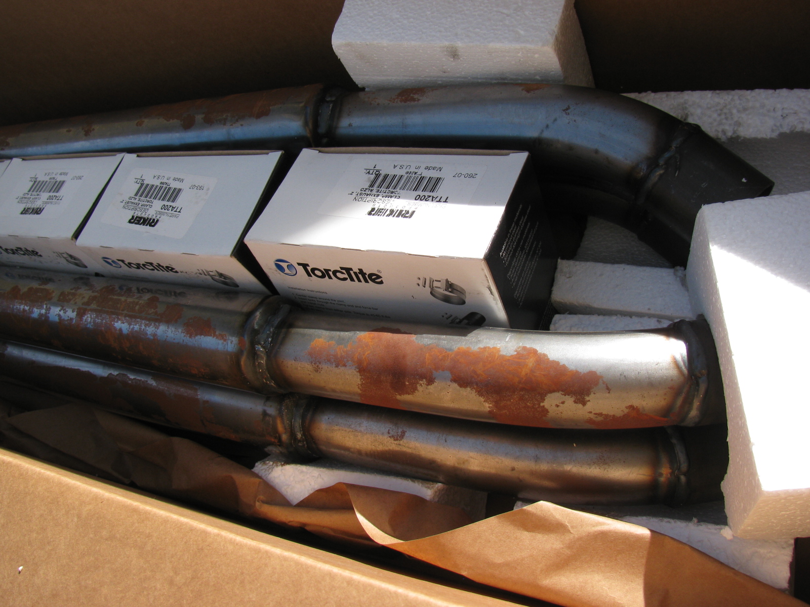
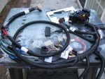
Here is the box of pipes and associated mounting hardware from The Factory. . .

Type 65 Coupe Exhaust, Uncoated, from Factory Five Racing, after one year
There is an option to get the pipes ceramic coated, I probably should have ordered the exhaust with the coating. I noticed the brochure on the Factory Five Racing website has the exhaust listed as ceramic coated at no charge. I wonder why I missed that part?
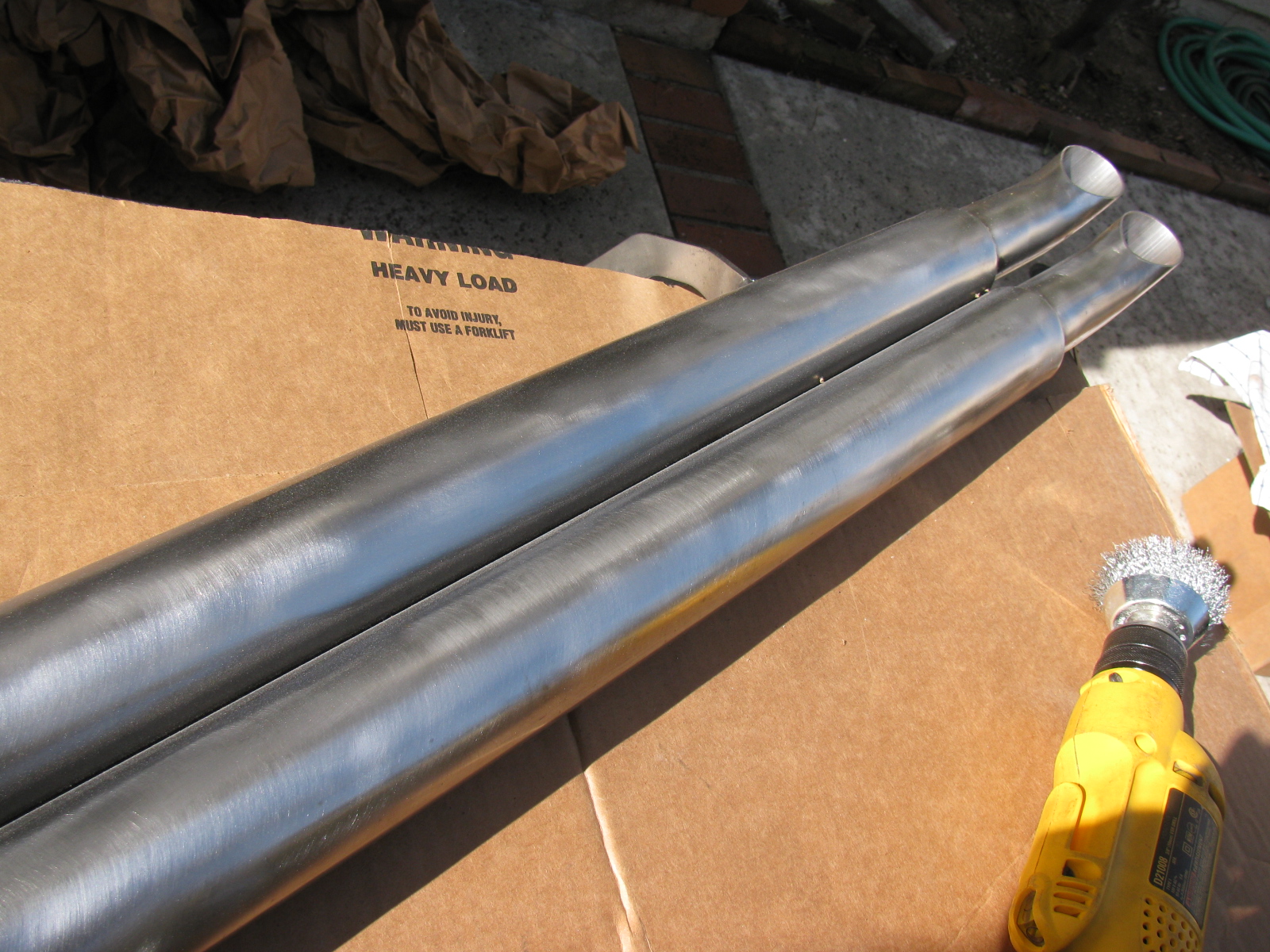
I used silver Rustoleum BBQ paint (Ultra) to finish the exhaust. But first, I prepped the pipes with wire brushes, to remove the rust and roughen up the surface, and then wiped them with acetone to degrease so the paint will stick better.

I used a wire brush on a drill motor to get the rust off and roughen the surface.

Type 65 Coupe side exhaust pipes painted with silver BBQ paint – I think it looks OK.
The BBQ paint is a bit soft, I think this is because it needs to expand and contract when heated and cooled. But it will be easy and cheap to touch up.
I am not sure what the final exhaust side pipe color will be, so I sprayed three coats of the silver on just to prevent further rusting. I may change the color to black, since I want the main body to be white.
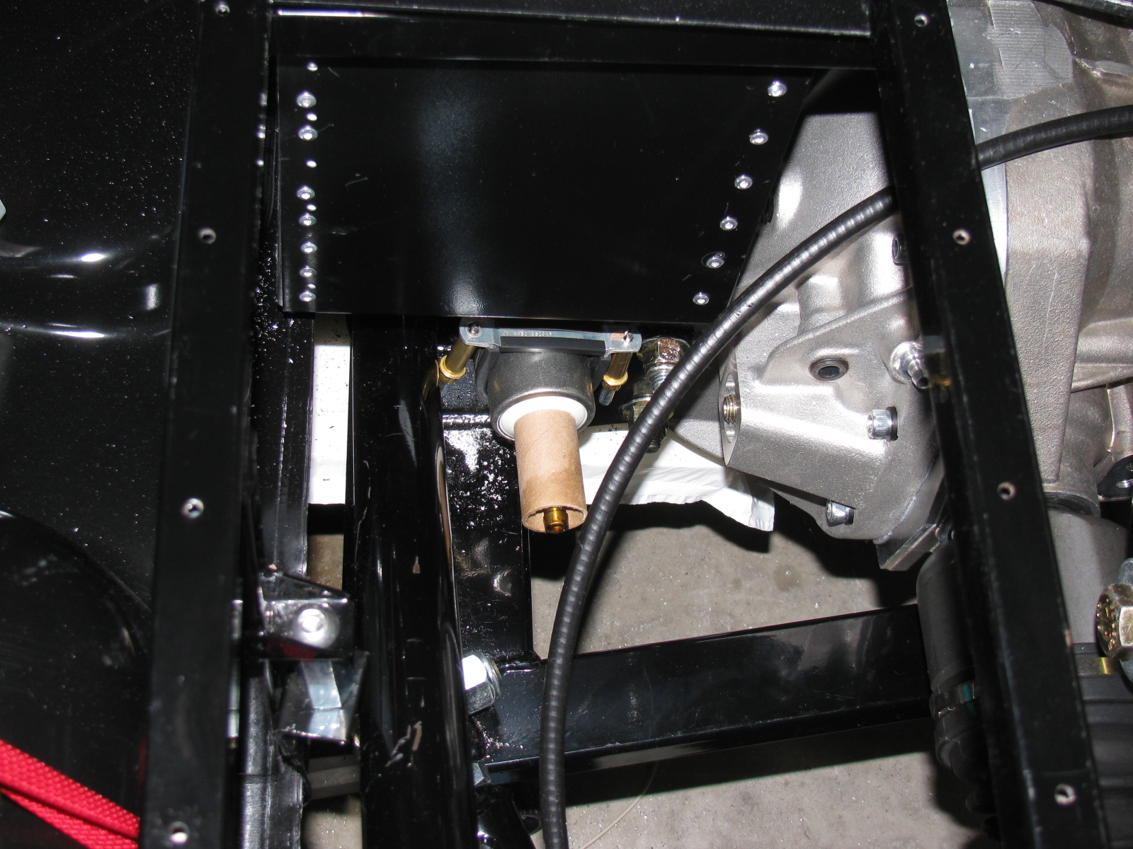
I did manage to mount the pre-filter for the fuel system. My 302 is fuel injected with an MSD Atomic EFI system, and came with most of the parts, including the fuel filters, hose, and external fuel pump. The first filter mounts where the Factory Five fuel filter is located, near the quad shock mount on the right side of the chassis. The MSD-supplied filter is smaller than the one supplied in the kit, so I had to figure out how to mount it. I am using a pair of electrical conduit clips to mount the first filter, as shown.

Electrical conduit clips are used to mount the first fuel filter to the chassis
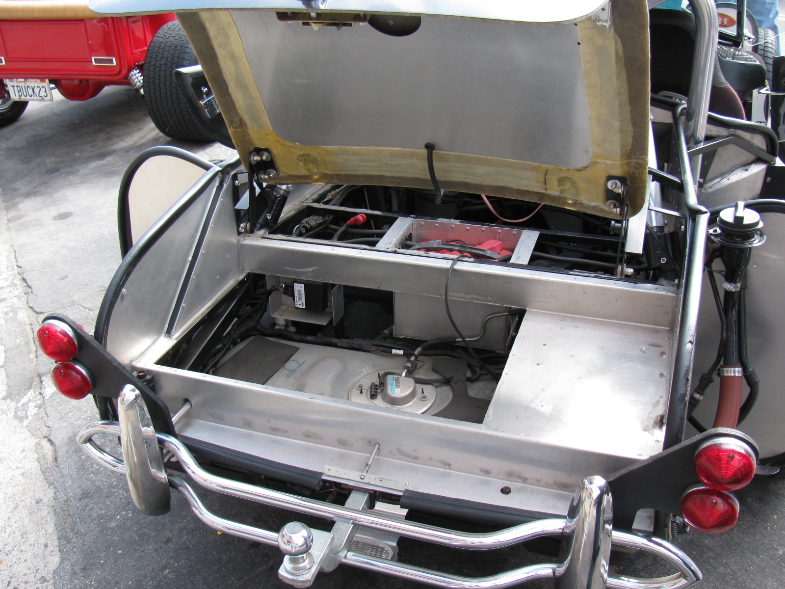
The fuel pump will mount to the bottom of the Factory Five Metal battery box. If you have IRS and want to use the same box, you must modify the battery box slightly, as mentioned in an earlier post. In addition, you will have to figure out how to make the battery box removable, since it will block the differential filler plug.
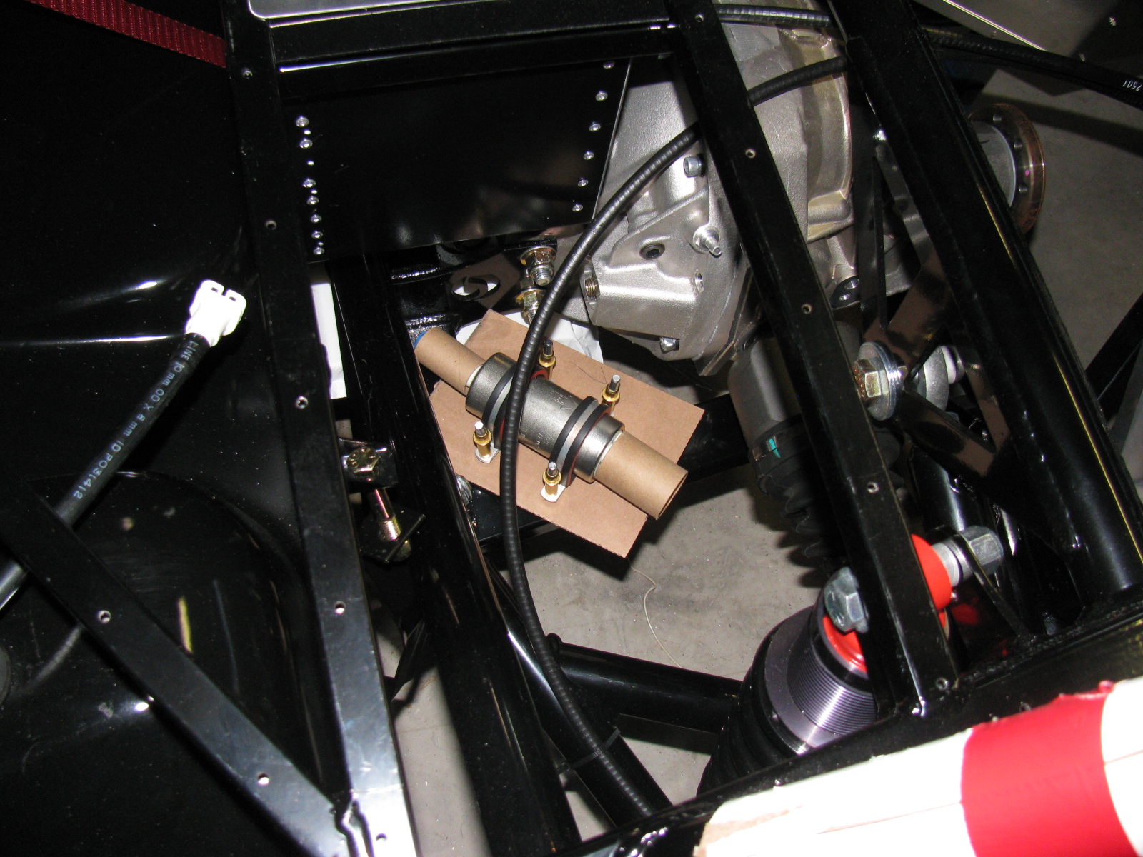
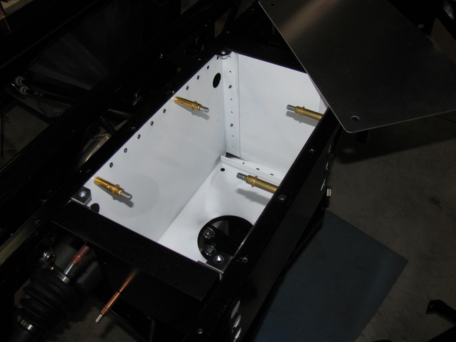
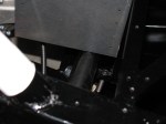
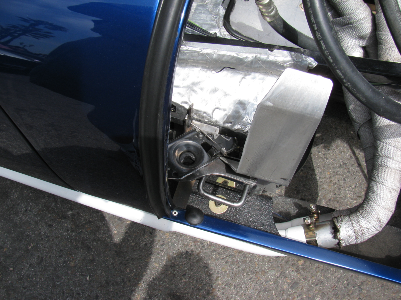
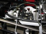
I will be mounting the battery box with nuts and bolts, and mount it so that it can tilt upwards for access to the rear end filler plug. More details and pictures will follow when I get to that chore. Here’s a sneak peek at where the external fuel pump will be mounted.

Type 65 Coupe with IRS – battery box and external fuel pump mounting location
I should have done more homework on this part of the build process, since Factory Five Racing tells us they do not include the fuel system. This makes sense since it will depend on the engine. I have a 302 with an MSD Atomic EFI system, and it came with the (external) fuel pump and filters.
So now I have to figure out how to get from the fuel tank output tube to the first fuel filter, then to the pump and then to the EFI unit. I decided to install a return fuel line, based on the information in the MSD instructions, I hope this extra effort will be worth it.
I will make access holes and hatches for the fuel pump and filter, as well the rear suspension components and tali lights – this should make maintenance and repair easier.
Here are some pictures of the work done today.

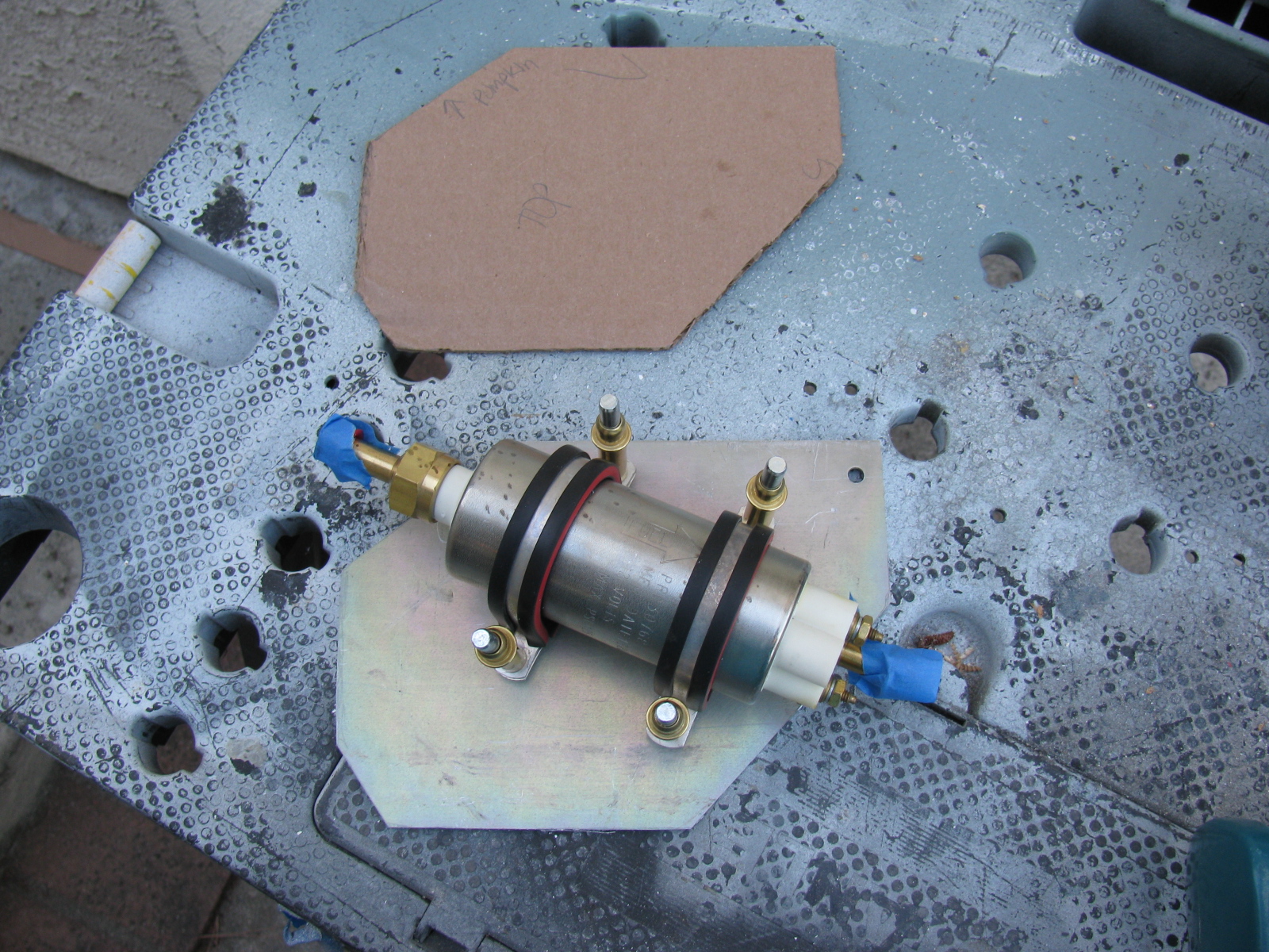
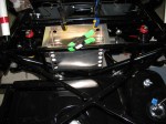
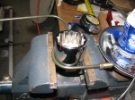
Type 65 Coupe fuel pump possible location. This is the external pump that came with the MSD Atomic EFI kit. The first fuel filter will mount to the battery box.

Using CAD – cardboard aided design, the fuel pump mounting plate is taking shape.

Here is the fuel pump in its possible location.

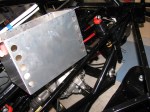
The cardboard template is transferred to aluminum. The mounting plate is almost a quarter-inch thick, so it will be nice and sturdy. This piece will be drilled and painted later.
By the way – the fuel tank is still not in its final location – the right side mounting bolts are not long enough. I may just get a length of all-thread and make my own bolt for that side. The left side seems to be OK. Next on the “To Do” list is fill and bleed the brake system.
I painted and installed the slightly modified battery box from FFMetal this past weekend. Just to be different, I decided to paint the box white on the inside and black on the outside.
As you recall from my previous Coupe update, the battery box fits very tightly into the chassis – and I figured out a way to install the battery box without scratching up the paint – the trick is to install and build the box piece-by-piece into the chassis space. In other words, do not assemble the battery box and then mount it into the chassis – instead, build the box into the chassis.
NOTE: By building the battery box into the chassis, adjusting one side of the box inward (as described in my previous battery box notes) may not be necessary. Try a dry-fit before you drill the side of the box to change the dimension slightly.
This is actually easy to do, but difficult to explain. Here are some pictures of the freshly-painted battery box installation:

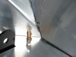
FFMetal battery box for the Type 65 Coupe – the individual parts are inserted into the frame one piece at a time, Cleco-ed into place, and then riveted. (Left side view.)

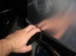
A close-up of the small cut needed on the left side of the battery box. This cut-out does not interfere with the battery – but the battery clamp bar may have to be moved, depending on where terminals, vents or filler caps are on the battery.

Another view of the two-tone battery box. I like the white interior, it makes it look nice and clean. Of course, a lid will cover everything later. . .

Another view. . .

The battery box with the supplied cover in place. Since I moved one side inwards, one cover screw does not line up properly. This does not bother me too much – I will install a small piano hinge at the upper side of the battery box, and the bottom two screws will hold the cover in place.
When the trunk floor panels are installed, I will make a cut-out to access the battery compartment. The instruction sheet shows how to make the cut-out in the floor panel, but I will make the cut-out with an easier technique that woodworkers use: A router and pattern bit. I will show how this is done when I get to that stage.
I may make a small finger-hole on the cover so it will be easier to open. Insulation and carpet will cover the entire trunk area later.
It’s been a long time since I posted an update on the Factory Five Racing Coupe. Here is an update in pictures and captions . . .
-
-
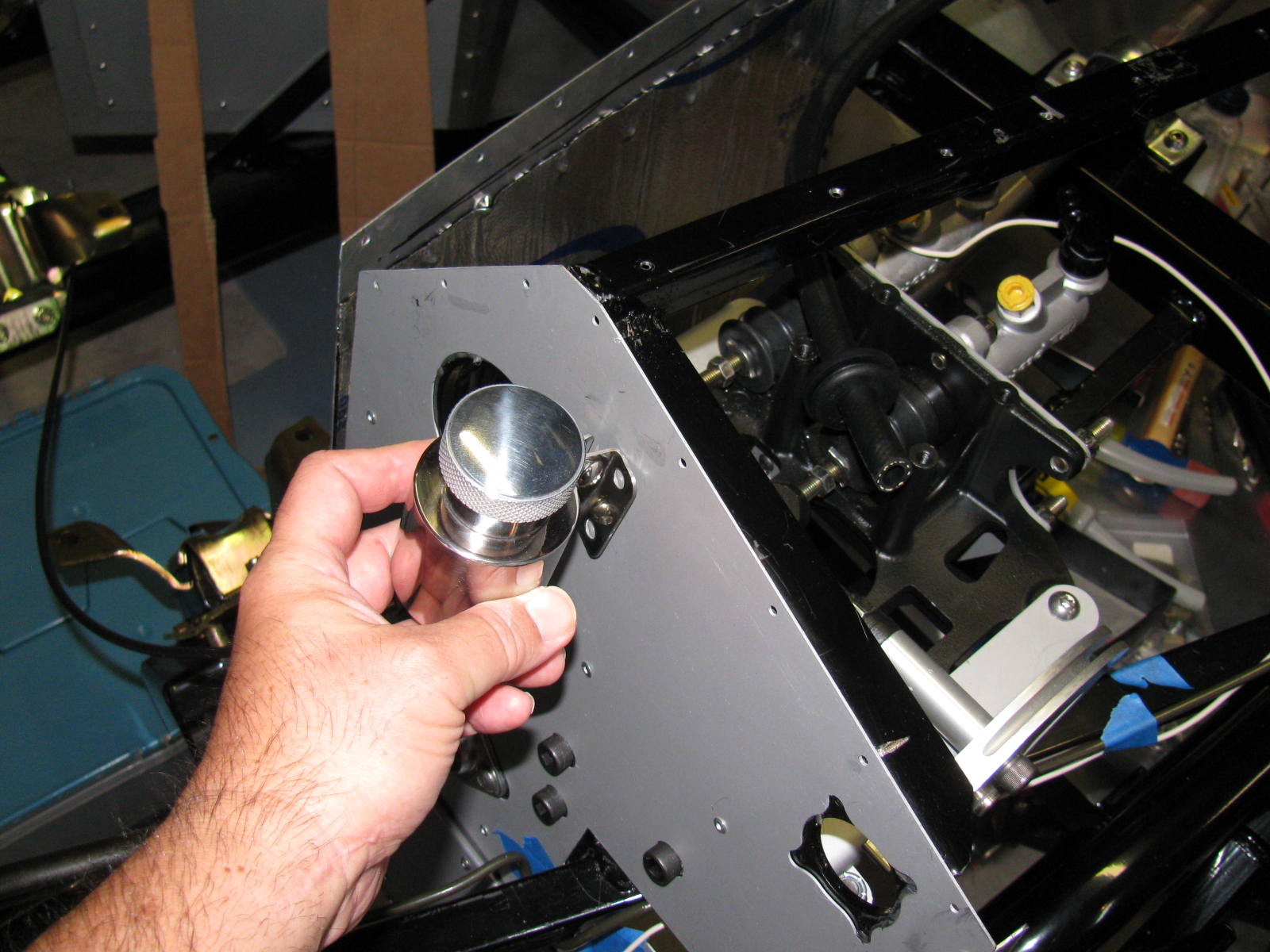
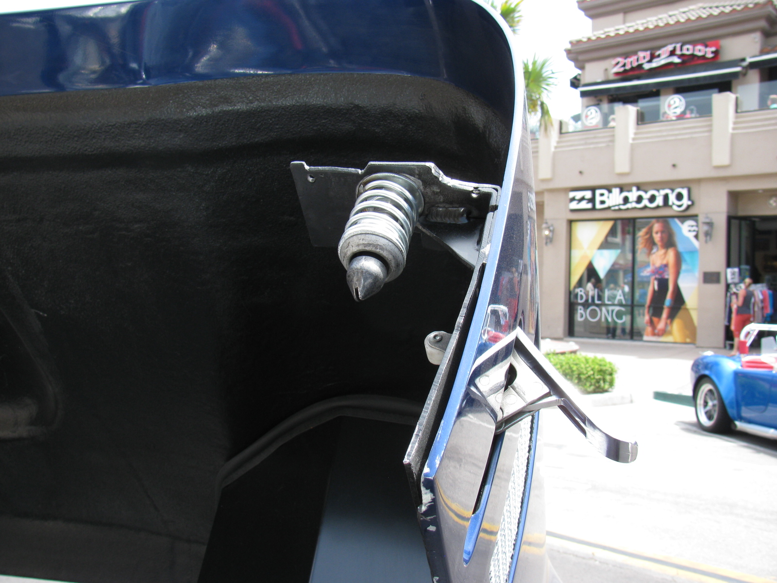
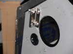
Type 65 Coupe complete kit brake reservoir bracket location
-
-
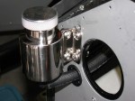
Polished stainless steel brake reservoir can, Type 65 Coupe, Complete Kit
-

-
I added a plastic grommet from the hardware store electrical section to prevent chafing the brake fluid hose.
-
-
I followed the hose layout as shown in the current Roadster build manual.
-
-
I used a big socket (35mm, I think) in a bench vise to bend my brake lines. Nothing fancy.
-

-
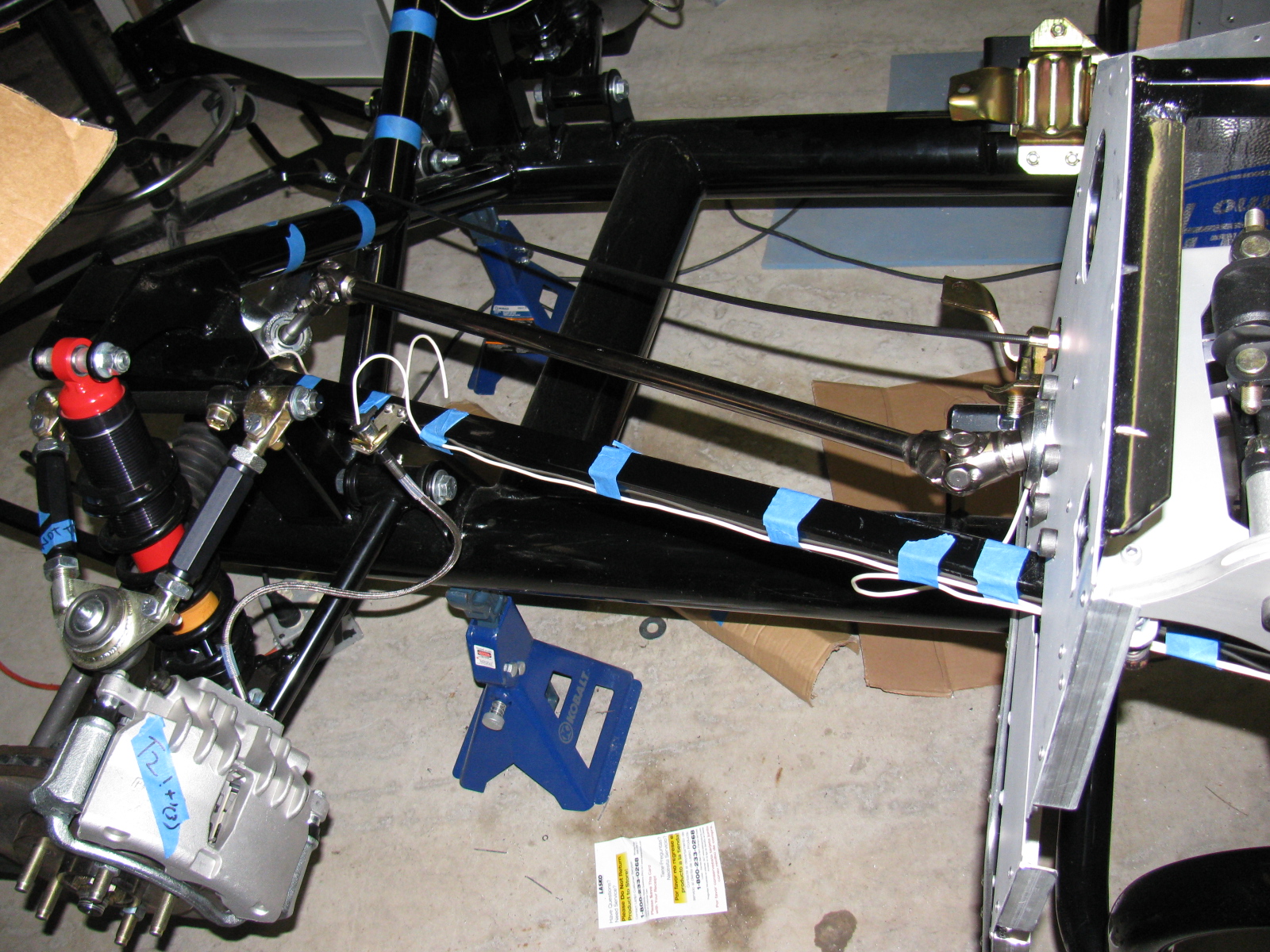
Brake lines are bent into rough shape, then taped in place along its route. Final bending is done on the chassis by hand.
-

-
Brake line held in place with tape, More adjustments are done by hand. Notice the way the excess lines are curved – this allows flexing in two planes – up and down and left and right. This is a 40-inch, pre-flared line I bought at a local car parts store. The supplied 60-inch line was way too long.
-

-
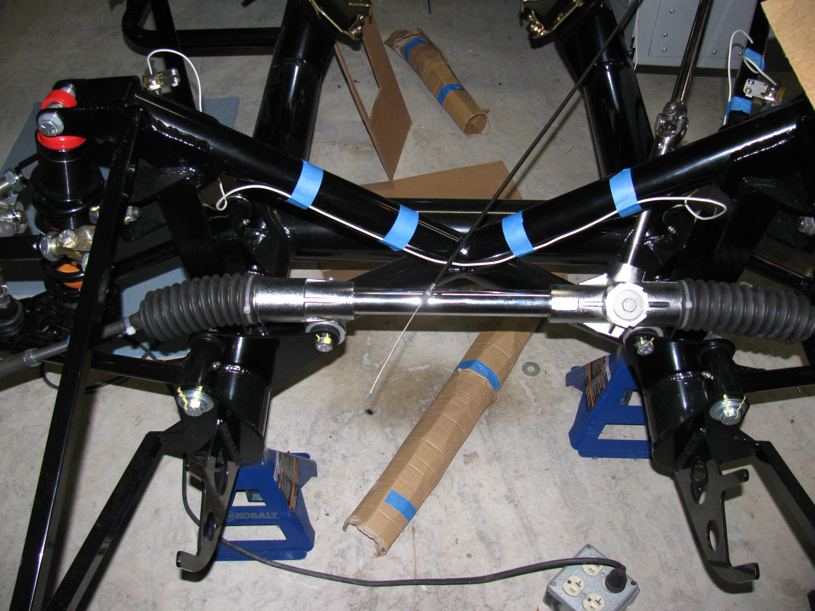
I start my brake line layout by marking the center of the span. This is the large rectangular tube going across the rear. The white wire (number 12 solid copper house wire) is used to make an extremely rough approximation of how the line will run.
-

-
Here you can see the white wire mock-up next to the steel brake line. The roughly Ohmega shape is centered above the IRS pumpkin.
-

-
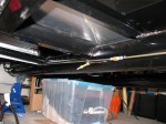
I decided to run the rear brake line on the inside of the firewall. It will look cleaner in the engine bay and will help keep the line cooler.
-
-
I got lucky. I used a 60-inch line from the rear master cylinder, down the inside of the firewall, and ended up under the driver seat area. A second 60-inch line goes from the union to the rear brake tee. No custom length needed.
-
-
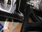
Here’s how the line goes up the support next to the lower rear sway arm. It will be slightly bent away from the chassis and held in place with the insulated line clips to prevent chafing.
-

-
Going up to meet the rear brake flex line, driver’s side.
-
-
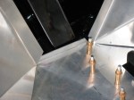
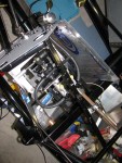
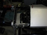
A peek into the pedal box – I am still not quite sure how this is going to work. The sheet metal on the right is going to be covered by the Coupe body, so this will be riveted – or screwed – into place. The open side on the left is going to have a one-piece cover. Will this provide enough access for brake balance and clutch cable adjustments?
-

-
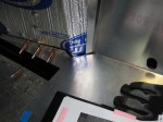
Inside the pedal box, showing the front brake line going to the master cylinder. Not as pretty as some others I have seen, but I can always re-do this later, right?
-
-
Here is a view of the rear brake line going to the second master cylinder. I drilled out one rivet fastening the sheet aluminum to the firewall and replaced it with an 8-32 stainless steel screw. It holds the line clip as well as the firewall panel.
-
-
Next on the to-do list: Wiring
-

-
Next on the to-do list: Fuel tank.
For some reason, things on the Coupe take much longer than I expect. I decided to practice running the brake lines today. I used some scrap number 12 wire, cut into five-foot lengths. The copper wire is much more flexible than the brake lines, but at least I can do a mock-up before I bend the real thing.
I am using the “FFR Type 65 Coupe build site,” by cbergquist1 on Flickr.com as a reference – click here to see Chris’ section on brake lines. http://www.flickr.com/photos/51103049@N00/sets/72157622122325431/
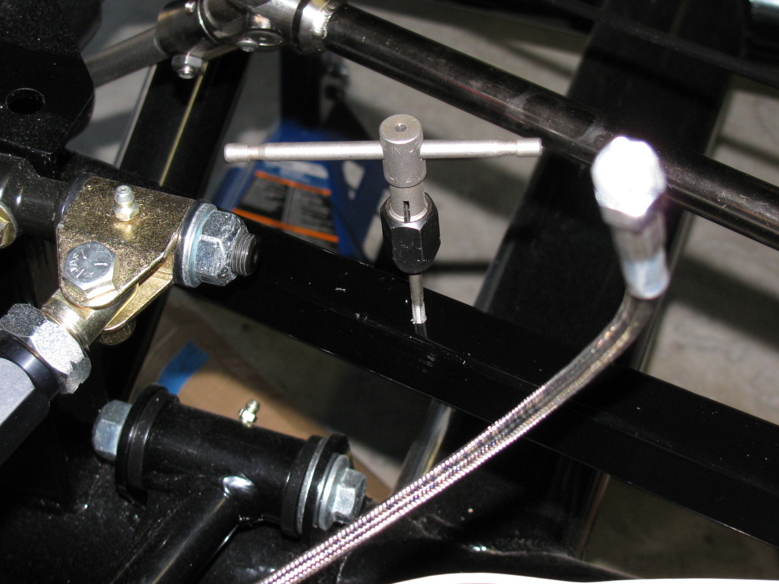
Just like Chris, I drilled and tapped holes for screws to mount the flex brake line mounts. I used 8-32 stainless steel button head screws. The Allen heads almost look like rivets.
Here are some pictures of my front brake line mock-up. . .


This is something weird. One of the mounting holes (on the left) was not punched out. I used an automatic center punch to knock the slug out.


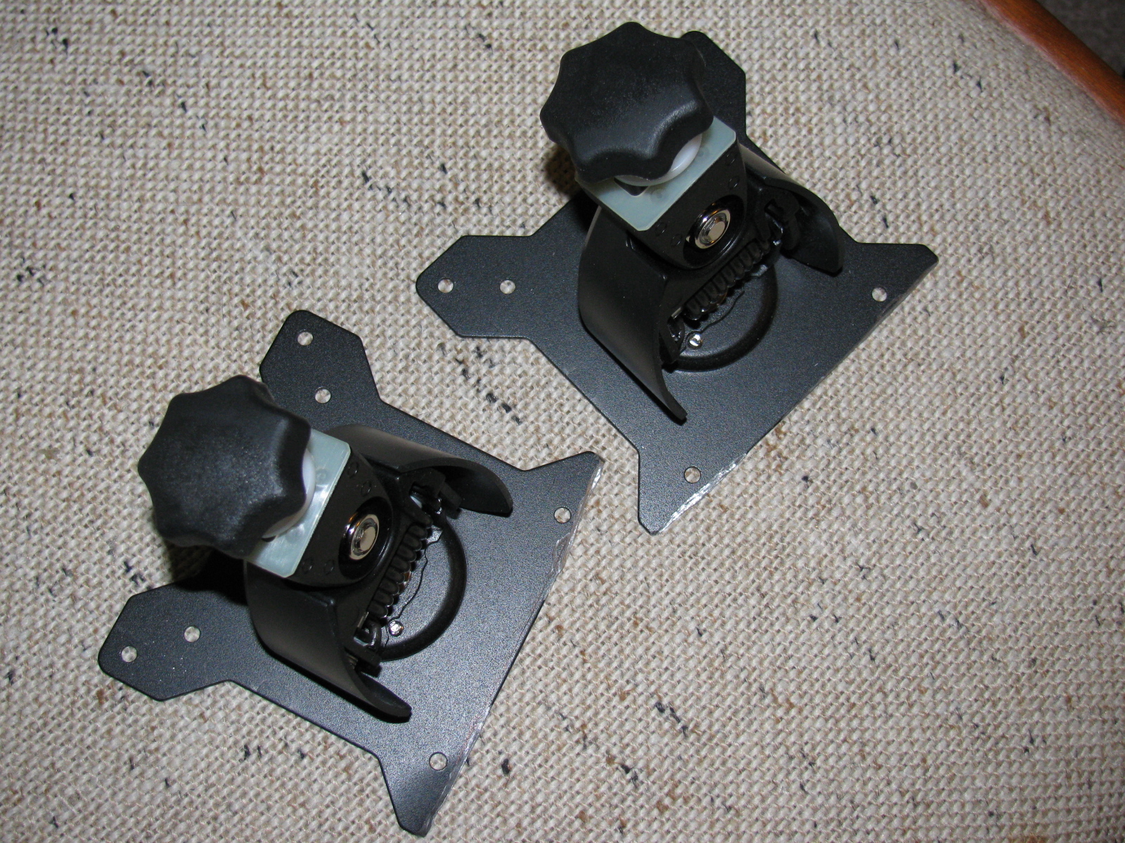
I took a time out to modify some monitor stand mounts for my office computer. The mounts were designed by monkeys, since they are useless and cannot be used out of the box. Actually, I should edit that statement, since I am not sure if the monitors or the monitor stands are wrong. In any case, some substantial cutting had to be done with my Dremel tool. I should have taken “before” and “after” pictures, but I wasn’t thinking. Here is a picture of the after-cutting operation. . . .

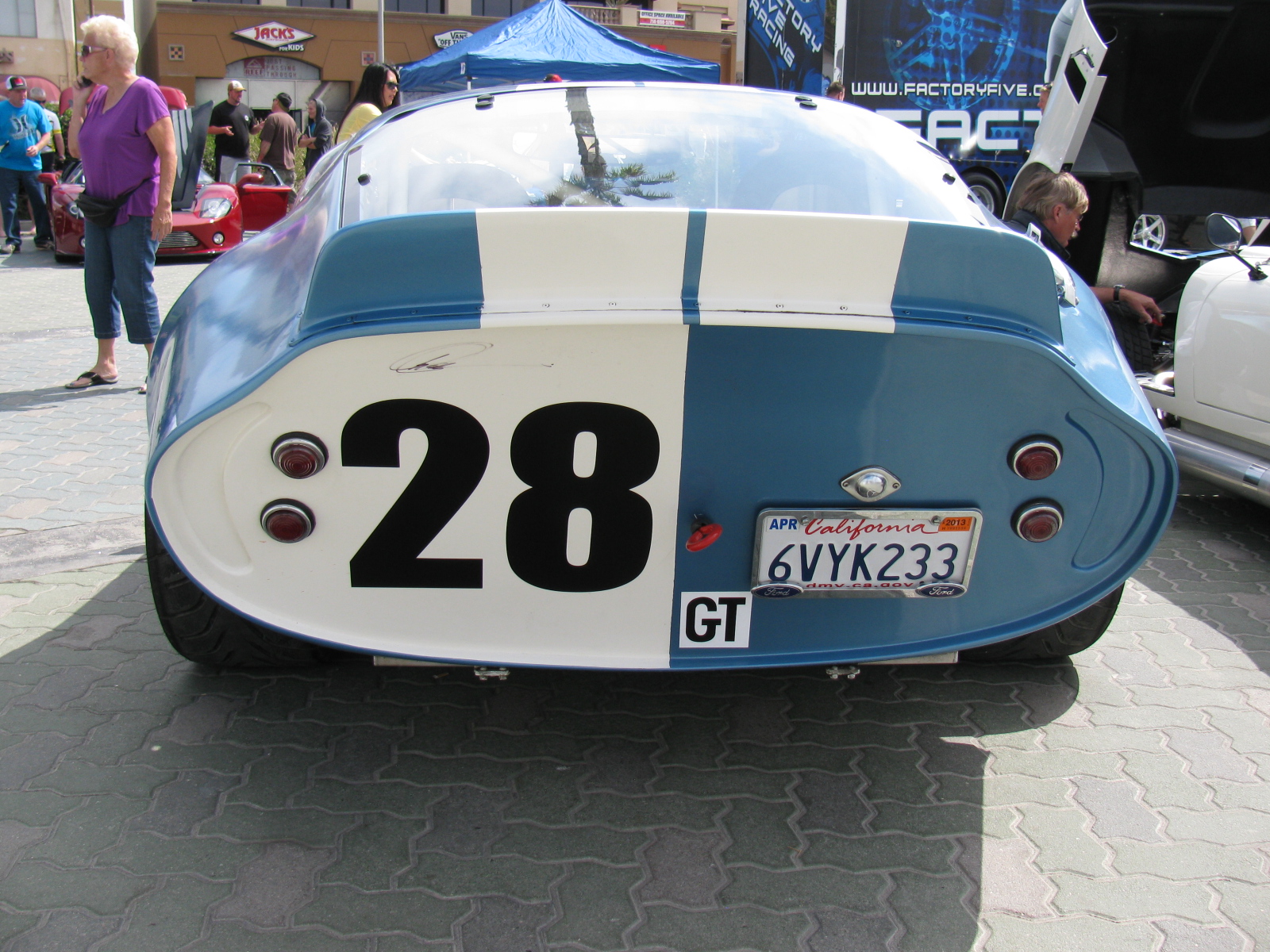
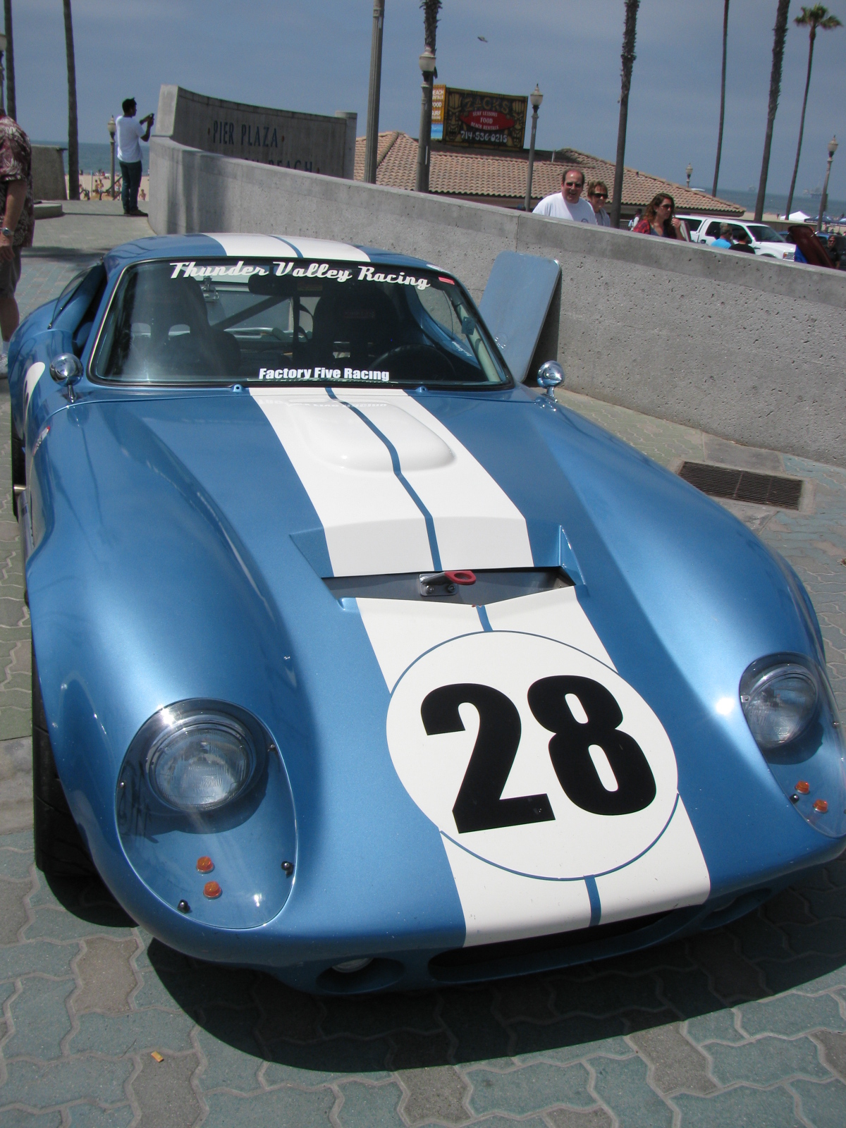
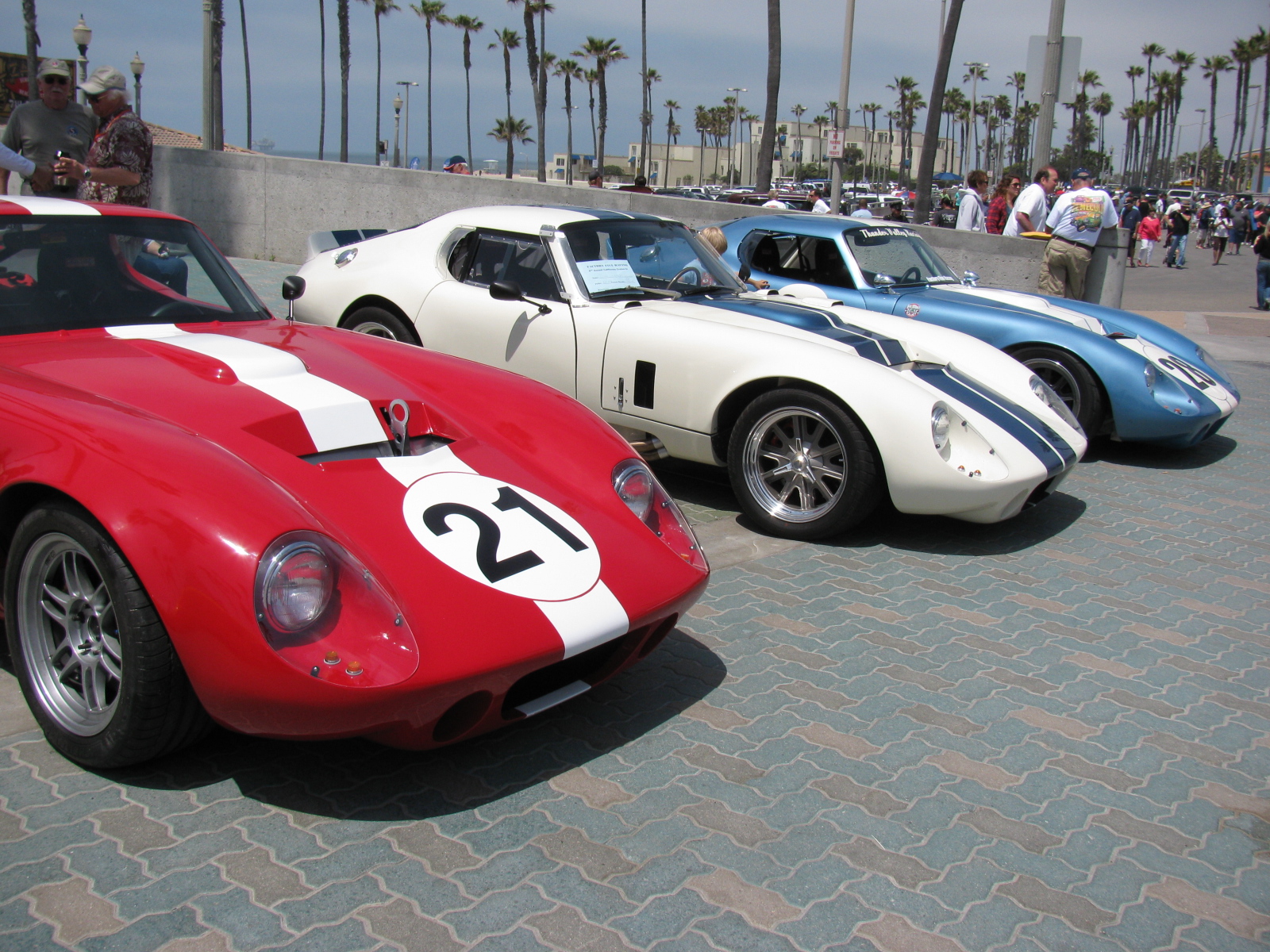
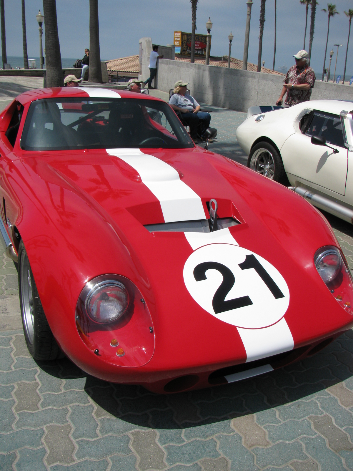
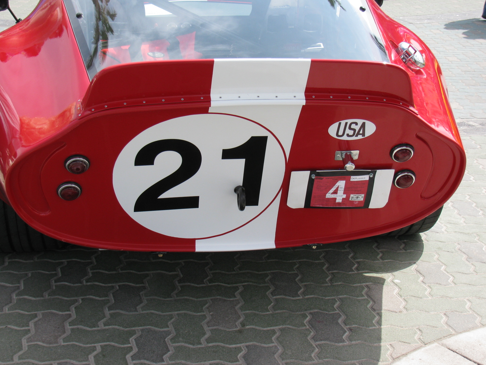
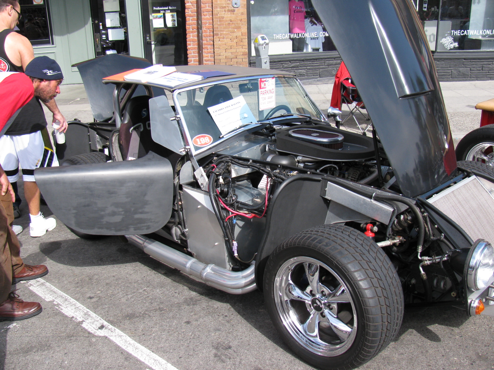
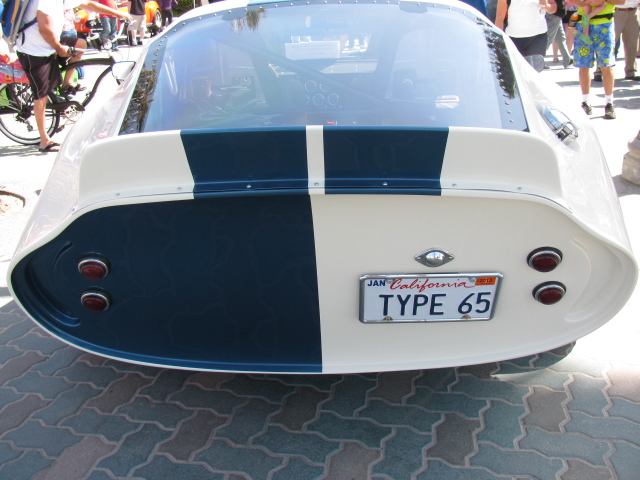
HUNTINGTON BEACH, Calif. — April 27, 2013 — Huntington Beach Pier Plaza and Main Street were filled with car enthusiasts and their hand-built sport cars from 9 am to 4 pm today. This was the sixth annual Factory Five Racing Huntington Beach Cruise-In which included over 100 Factory Five Racing cars, each one custom hand-built. Other custom and street cars were also on display, and included a vintage Chevrolet Corvette, and Ford GT.
Factory Five Racing is located in Wareham, MA and currently offers five component car kits, the Mk4 Roadster, the Type 65 Coupe, a classic ’33 Hot Rod, the GTM Supercar and the newest model called Project 818. Pricing varies depending on the kit configuration and accessories and options. In addition to the kit, builders supply their own engine, transmission, wheels and tires and finish and paint.
Dave Smith, president of Factory Five Racing, is a hands-on guy, and is involved in every aspect of his company… and is the friendliest person you’ll ever meet. He loves talking about his – and our – cars, and Dave says every time he meets people at these gatherings, he learns something new from each builder.
More information is available on the Factory Five Racing website, www.factoryfive.com
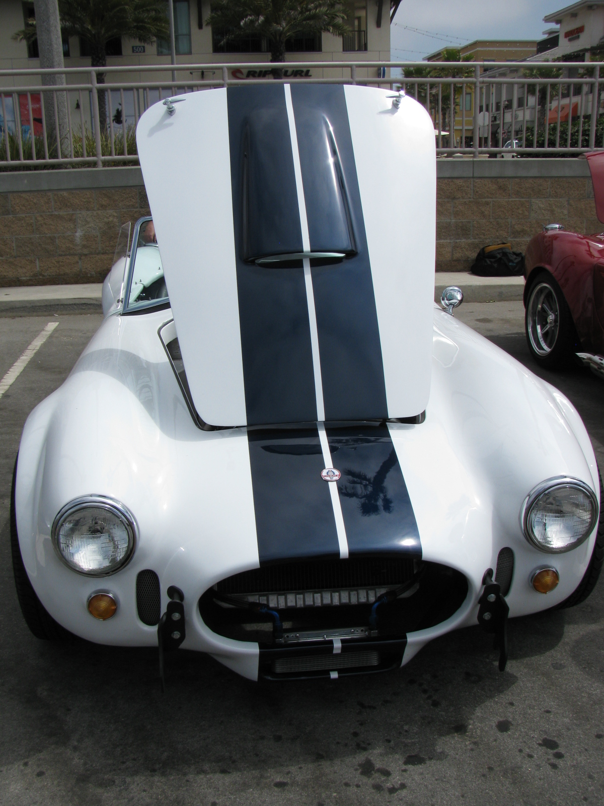
My mission at this year’s event: To gather more information on the E-brake cable routing, look at paint color combinations and get some more ideas for dashboard layouts.
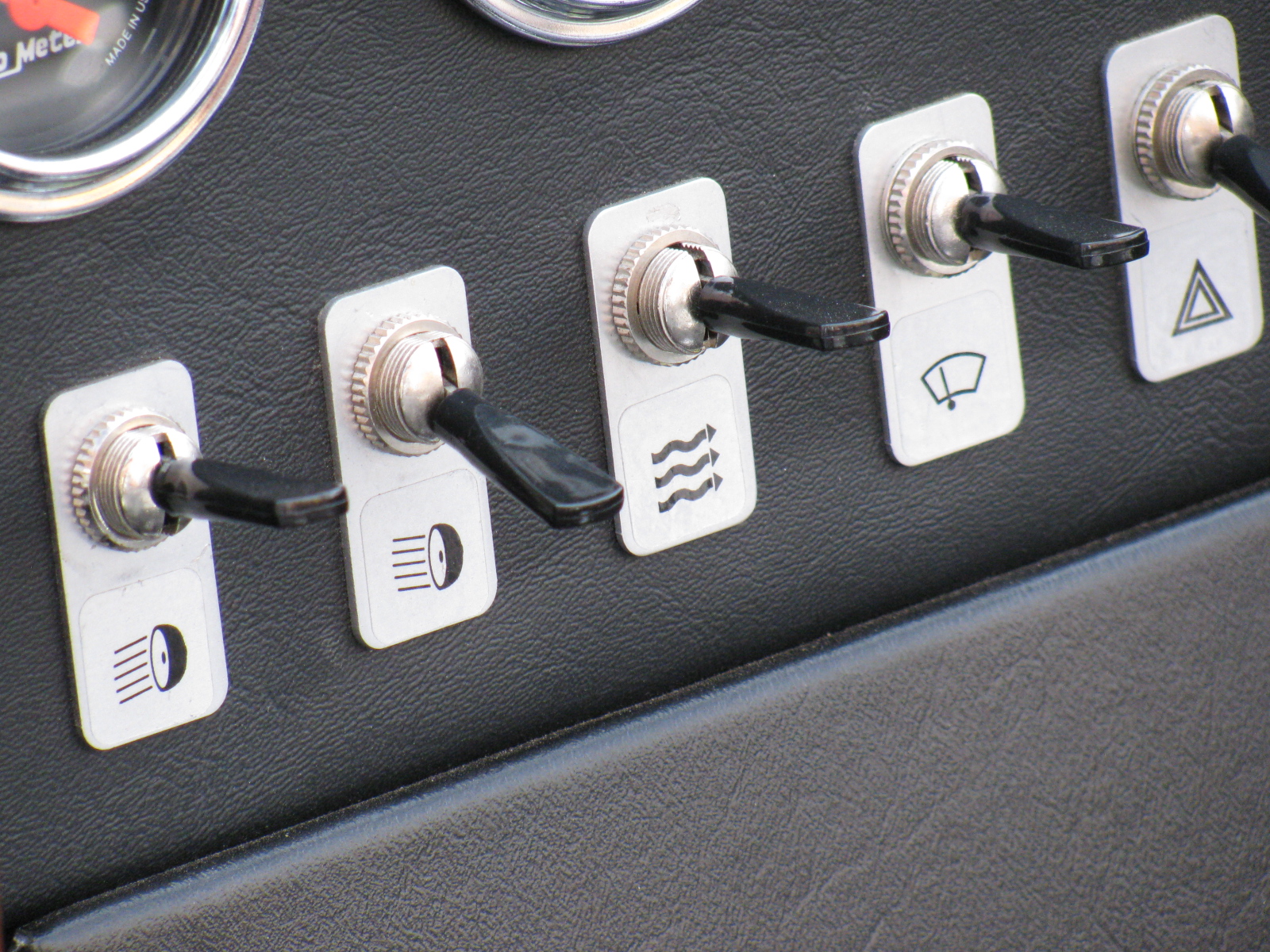
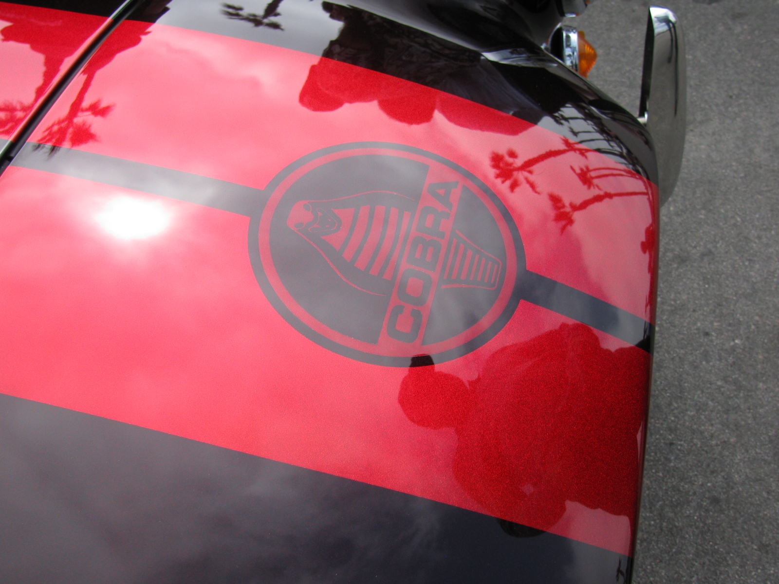
I had always planned on a white body/black or blue stripe Coupe, but after seeing these other paint jobs, I may change my mind. LED headlamps, cool-looking switch name plates, BRE side mirrors for the Coupe, honeycomb (hexagonal hole) screen for the side vents and other ideas are shown in these photos.
Thanks to everyone displaying and explaining and answering my questions about their cars today, and it was great to meet the Southern California – and other area – builders in person at this event.
Here are some random images from today . . .


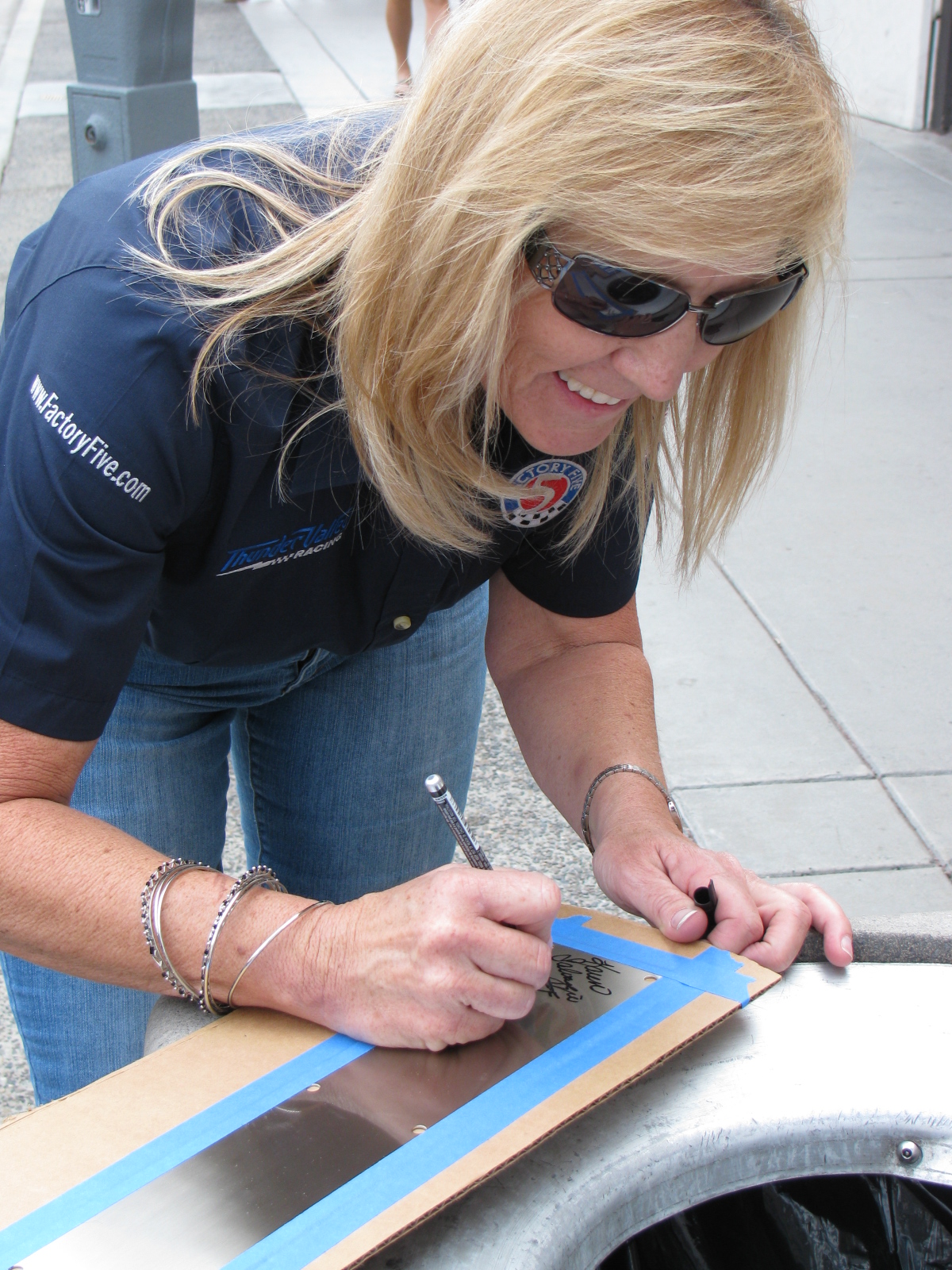
Above – Dave Smith, Factory Five Racing president, telling another great car story. . . Karen Salvaggio, Thunder Valley Racing Owner (and driver of the Type 65 Coupe number 28), signing my “signature plate” that will be mounted on my Type 65 Coupe dashboard – this will fill that big blank spot nicely. Take a look at Karen’s website and her blog posts for more informaton on her team and the cars they race. www.thundervalleyracing.com and http://thefactoryfiveforum.com/entry.php?346-Coupe-Challenge-Building-a-Legend


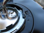
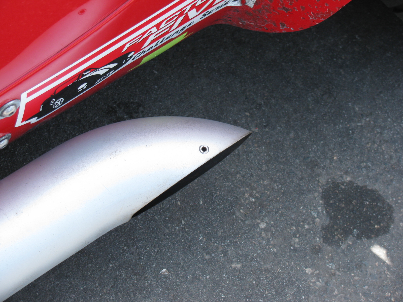
Anyone know what this hole is for on the Roadster exhaust?


6TH ANNUAL FACTORY FIVE HUNTINGTON BEACH CRUISE-IN click here
Here’s a short video of last year’s Moment of Thunder – click here
Some images from last year. . . .