Archive for the ‘10 GHz’ Tag
The ARRL 10GHz and Up contests are coming up soon (August 17 to 18 and September 21 to 22), so I thought I’d re-publish my article that originally appeared in The Proceedings of Microwave Update 2005.
The Harris-Farinon Model SD-108175 / 076-108687-001 solid state power amplifier (SSPA) has been seen globally on the surplus market over the last few years. This amplifier is a part of a large rack of equipment running on the traditional 24VDC, positive ground telecom power system bus.
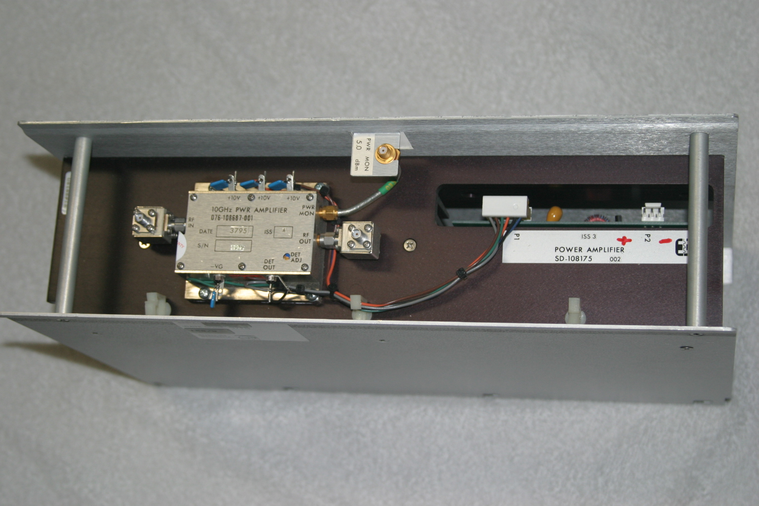
In its original form, the amplifier is very robust and heavy, since it is rated for continuous duty, Class A operation. Figure 1 shows the unit as received. It is mostly heatsink, and the RF unit, where the microwaves are amplified, is the tiny silver box on top.
The SSPA unit (Model SD-108175) measures about 15-1/2 inches wide, 4-1/4 inches high and 10 inches deep, and weighs over 15 pounds. The little silver box (part number 076-108687-001) with SMA isolators at the input and output, is about 3 inches wide, 1 inch high and 2-1/2 inches deep.
Important: Be careful if you see these units for sale, I have seen some inaccurate descriptions of these units – for ham radio use, the only item we want is just the amplifier (076-108687-001) and not the heatsink/chassis assembly or the power supply DC-DC converter.

Figure 1. The Harris-Farinon 10GHz amplifier is very beefy, but it is mostly heatsink. The little silver box is where the RF is amplified.
I took the unit to Dave Glawson’s lab (WA6CGR) to see if we could integrate this SSPA into my X-band rig. It is a 1W unit, but I have several that put out as much as 3W on 10368 MHz. I purchased several of these units at a very reasonable price, and am pleased with their performance on the 10 GHz Amateur Radio band.
The terminals on the amplifier as well as the power supply PCB are marked, simplifying some of the guesswork about what-goes-where. The amplifier includes a “POWER MON” SMA female jack, which should probably be capped with a 50Ohm termination to prevent oscillations or weird things from happening while the amplifier is operating. A “DET OUT” pin is useful to verify amplifier operation.
It may be prudent to read Chuck Houghton’s article, “Above and Beyond, Microwave Stripline Retuning Procedures” on tweaking circuits before any “poking around” is done on any SHF amplifier, to prevent damage. Links to references are at the end of this article.
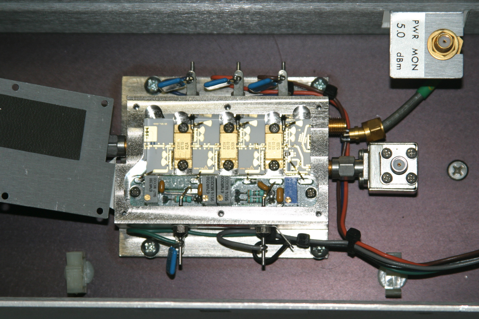
The first step is to power it up and verify operation in its “as-is” state. With about +17dBm (about 60mW) input, power output is about +35dBm, or a little over 3W at 10368MHz. Current consumption is about 2.6A during standby and about 3A at 10V with RF applied. Dave and I wondered whether or not we could tweak the amplifier to get more power out, so we took a look under the lid of the little silver box, see Figure 2. We decided not to tweak anything inside the tiny box.

Figure 2. A peek inside the SSPA. No tuning is required to get two to three watts output on 10368MHz.
Since the amplifier passed its first tests, the next step is to re-package the unit so it would be more suitable for portable and roving operations. Certainly, a weight reduction could be done by shrinking the size of the RF module heatsink, and adding a fan or two.
Since the amplifier passed its first tests, the next step is to re-package the unit so it would be more suitable for portable and roving operations. Certainly, a weight reduction could be done by shrinking the size of the RF module heatsink, and adding a fan or two.
The DC-DC Converter
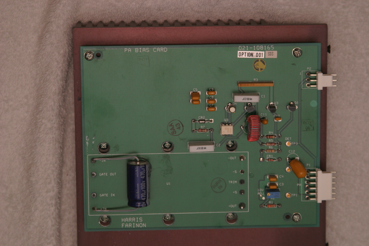
The original power supply board appears in Figure 3. A casual inspection of the unit showed that the 24V input was buck-regulated down to 12V, and then further reduced to minus 2.1V for the bias and +10V for each stage in the amplifier. The DC-DC power supply looks like it can be modified and re-used, by applying 12VDC where the brick converter has its output. However, this modification was not attempted.

Figure 3. The DC-DC supply board. A 24V to 12V brick converter is mounted to a 14-1/4 inch by 7-1/4 inch heatsink under the PCB. The existing DC-DC converter may possibly be modified to make the unit work on 12VDC input. See text.
I thought a better, lighter, more modern power supply could be built fairly easily, and the large heatsink for the power supply could be deleted.
With Dave’s help, I made a simple DC-DC converter using a Linear Technology LT-1083 adjustable regulator and a few resistors for the +10V supply. The negative bias supply was made from a surplus 99-cent DC-DC converter. I built the power converters into separate chassis boxes, since I had them on-hand. A single box is also acceptable.
Like all FET power amplifiers, one must make sure that the minus (gate) bias supply is always connected before the supply voltage to prevent damage to the devices. I am sure there are several solutions for power-on sequencing to prevent this from happening, including relay or other switching or timing schemes. However, I chose a very simple route: I simply wired the minus voltage directly to the amplifier bias feed-thru capacitor, with no switching in-between. The plus 10V supply line is switched to the amplifier via a power relay, actuated by the sequencer. This way, whenever the rig is powered up, the minus bias voltage is “automatically” applied (it was never off in the first place), and the plus 10V is applied only when the rig is put into transmit mode.
I had a pair of 24V brushless DC motor fans in the junk box, so I am using these to blow on the heatsink. Since I have both 24V and 12V running around in my rig, I wired up a two-speed fan control using a pair of spare relay contacts. When the radio is in the receive mode, 12V is applied to the fans, reducing the noise. When the rig goes into transmit mode, 24V is applied to the fans, running them at full speed.
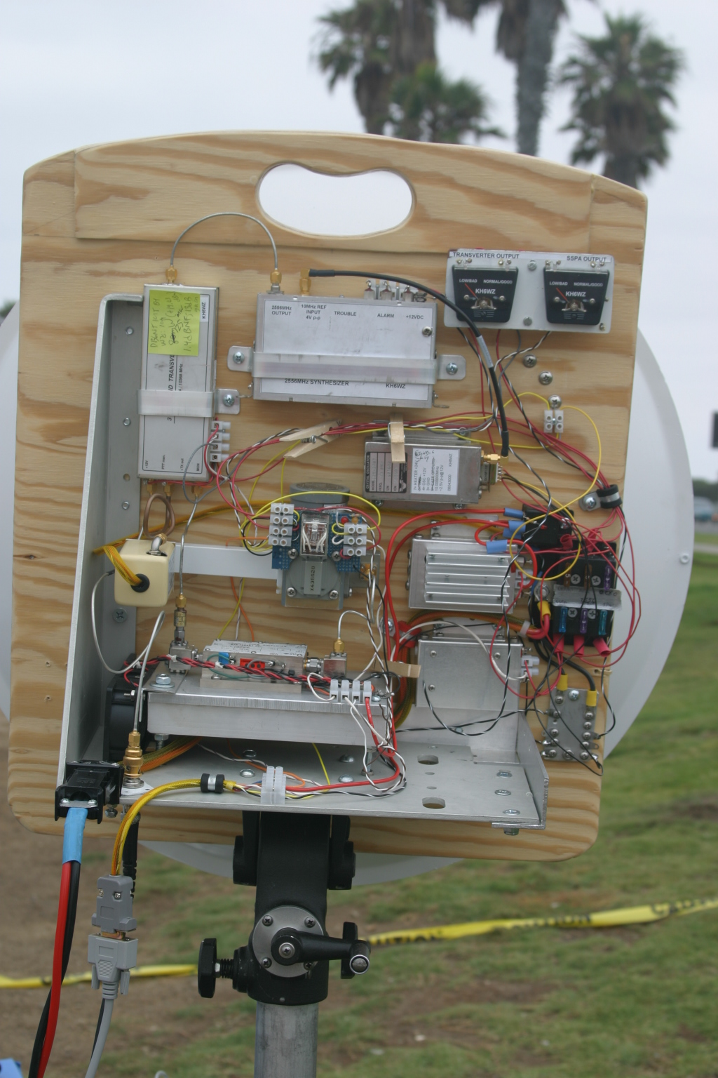
The final result is shown below. The amplifier is mounted in one of my 10GHz rigs, “Ms. June.” 3 The SSPA puts out 2W at the antenna port, and now measures about 4 inches by 7 inches by 1-1/2 inches, including the cooling fans. A re-labeled, surplus CB panel meter (1mA movement) connected to the DET OUT pin indicates SSPA operation. (Update: Ms. June was cannibalized for parts. However, many of her parts were used in other radios, including my latest, record-setting 10GHz transverter.)

Figure 4. The Farinon SSPA installed in “Ms. June,” one of my early 10GHz rigs. Two watts appears at the waveguide port at the antenna relay in transmit. The DC-DC converters are enclosed in separate chassis boxes, and can be seen just to the right of the amplifier. A re-labeled surplus meter monitors amplifier operation.
References
1 – “Above and Beyond, Microwave Stripline Retuning Procedures,” by C. L. Houghton, WB6IGP, San Diego Microwave Group:
http://www.nitehawk.com/rasmit/mstrp_tu.html
2 – The surplus TDK DC-DC converter is described as a “5V in +/-5V DC/DC converter” at MPJA Online, as part number 1042518. This unit is under a “closeout” deal, so supplies may be limited. Go to http://www.mpja.com, and look under “Power Supplies,” “DC-DC Converters.” Their phone number is 800-652-6733, 9AM to 5PM Eastern Time, Monday through Friday. Although probably not necessary, I removed the TO-220 device from the board and re-mounted it to the metal chassis box for heat-sinking.
3 – Most of the SBMS members have names for their rigs, mainly because, as many of you know, microwave radios tend to have personalities of their own. Ms. June is my sixth 10GHz radio re-build. “Morpheus” was my first attempt, see CQ magazine for December 2003 and January 2004 for my dubious start on the microwave bands.

Maker Walt discussing something fascinating with Jeri Ellsworth, aka “Circuit Girl.” Photo by Tony KC6QHP
Here is a report on the 2013 Maker Faire by Tony Long (KC6QHP):
Another great Maker Faire is in the books, amateur microwave radio was well represented!
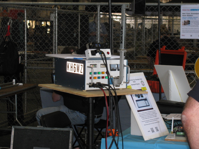
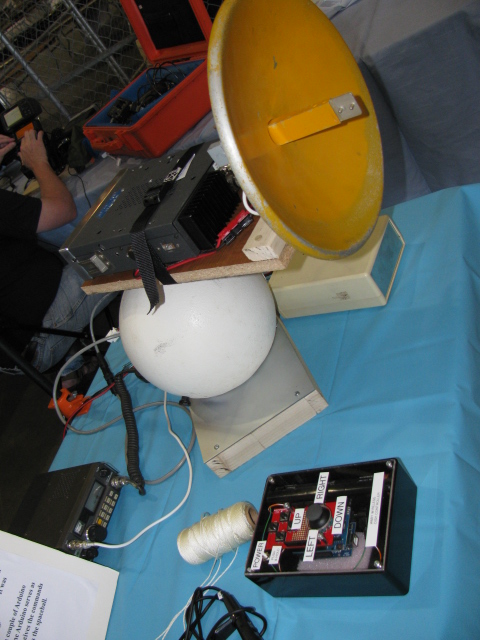
Thanks to the coordination efforts of Wayne KH6WZ, Brian W6BY, the 50 MHz and Up Group, the SBMS, and UC Davis, the “Not Your Grandpa’s Ham Radio 2” booth at the Maker Faire was a great success.
This year we shared a booth with UC Davis whose impressive student projects ranged from a radar demonstration, to video processing, audio sequencing, and mechatronics. Along with that, we had a 10/24 GHz SDR setup courtesy of Dennis W6DQ (on a big screen courtesy of Brian), some of Brian’s homebrew gear, Walt’s EM field demos and transceivers, and some of my stuff including a 10 GHz radio and beacon.
LA Times says that about 165,000 people were expected to attend this year, so at a minimum 10,000 people passed by our booth. Our raspy voices are an indicator that a great deal of talking was done! I personally interacted with a number of people who are really interested in amateur microwave radio and if even a fraction of them get involved or raise general awareness, I think it is a success.
Walt’s demos, owing in part to their elegant simplicity and visual nature attracted a lot of attention and interest. On Sunday night he took them to a post-fair get-together with the who’s who of the hardware hacking scene (Jeri Ellsworth, Ben Heckendorn, Diana Eng, Alan Yates and many many others). All were impressed!
Something I see very encouraging in the “maker” scene is a real interest in RF. This crowd includes a good deal of embedded systems engineers, talented software people, etc. There’s a real opportunity to make connections with this crowd and get more activity on the microwave bands.
As Software Defined Radios decrease in cost and become more open source, I predict massive interest in RF and likely in the microwave bands because of their large bandwidths. While they may not be interested in SSB mountaintop to mountaintop contesting (there will be those who are certainly), an increase in use of our bands will only help to further the cause of maintaining our spectrum to help further the state of the art.
I posted a gallery of pictures on Flickr: http://goo.gl/cAy3p
Tony KC6QHP”
Thanks for the report, Tony!
Make: Magazine reports there are over 900 displays this year. My team is setting up for the big event. I will post images and reports as soon as I receive them from my crew. I am not going this year. . . .
Here are some previews and some of the things I want to see. . .

Read more at: Belt-Driven, Hubless Rear Wheel Bicycle

Read more at: The Viper 2.0

And of course, my entry, Not Your Grandpa’s Ham Radio 2
I got tired of fiddling with the IRS so I did something different this weekend. Here is a picture of the E-brake ratchet handle that comes with the Complete Kit. Since the parts are plain, un-finished steel, I decided to paint it to prevent rust. The exploded view in the instructions make assembly very easy. I wish The Factory would include an exploded view for the IFS as well as the IRS – makes things go so much better. The finish is white and black appliance epoxy from Rustoleum.
Here are some pictures. . .


I am not sure if I like the location of the E-brake handle, it is on the passenger side of the transmission hump. A popular modification is to use a Pontiac Fiero unit and re-locate it closer to the driver. We’ll see if I want to change this setup. (The sharp-eyed people will notice the e-brake handle is backwards. . . . . . )
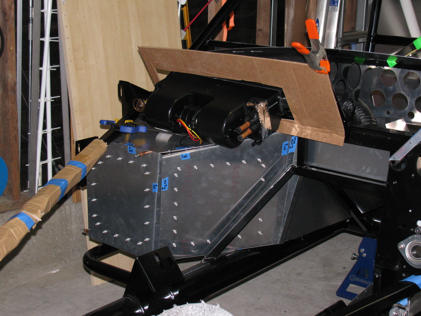
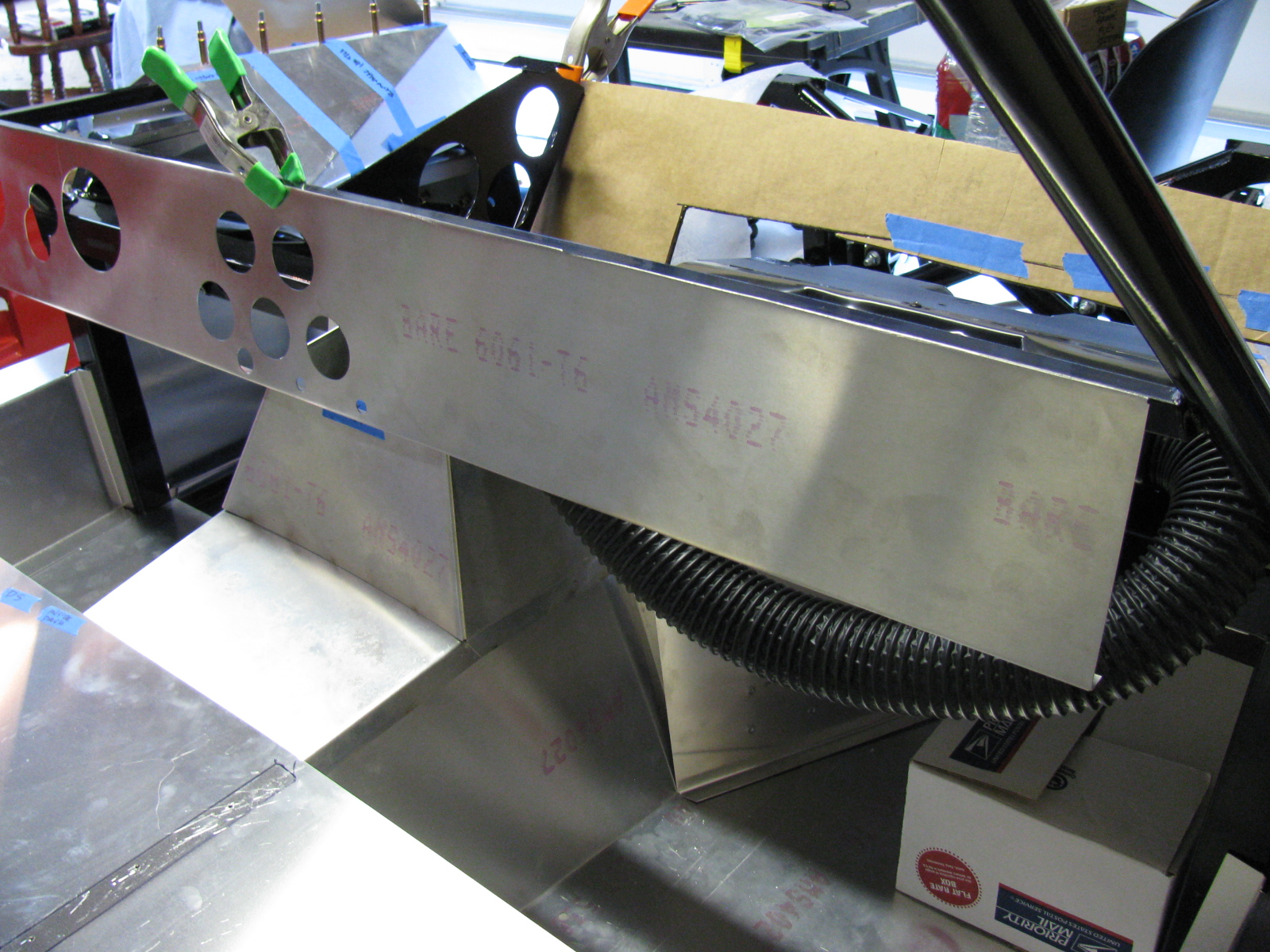
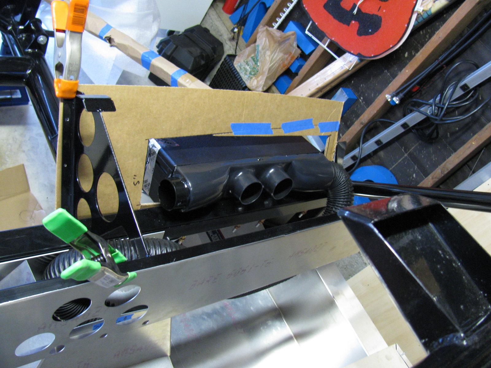
Here are some images of the air conditioner and a cardboard aided design (CAD) templates I am making. This requires some cutting of the dashboard and firewall, so I want to mock everything up before I start cutting. I have some very sturdy aluminium plates for the A/C baseplate, and some sheet aluminum for the enclosure. A CAD version will be made first, then transferred to aluminum.


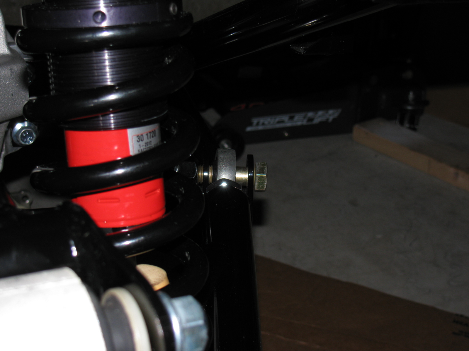
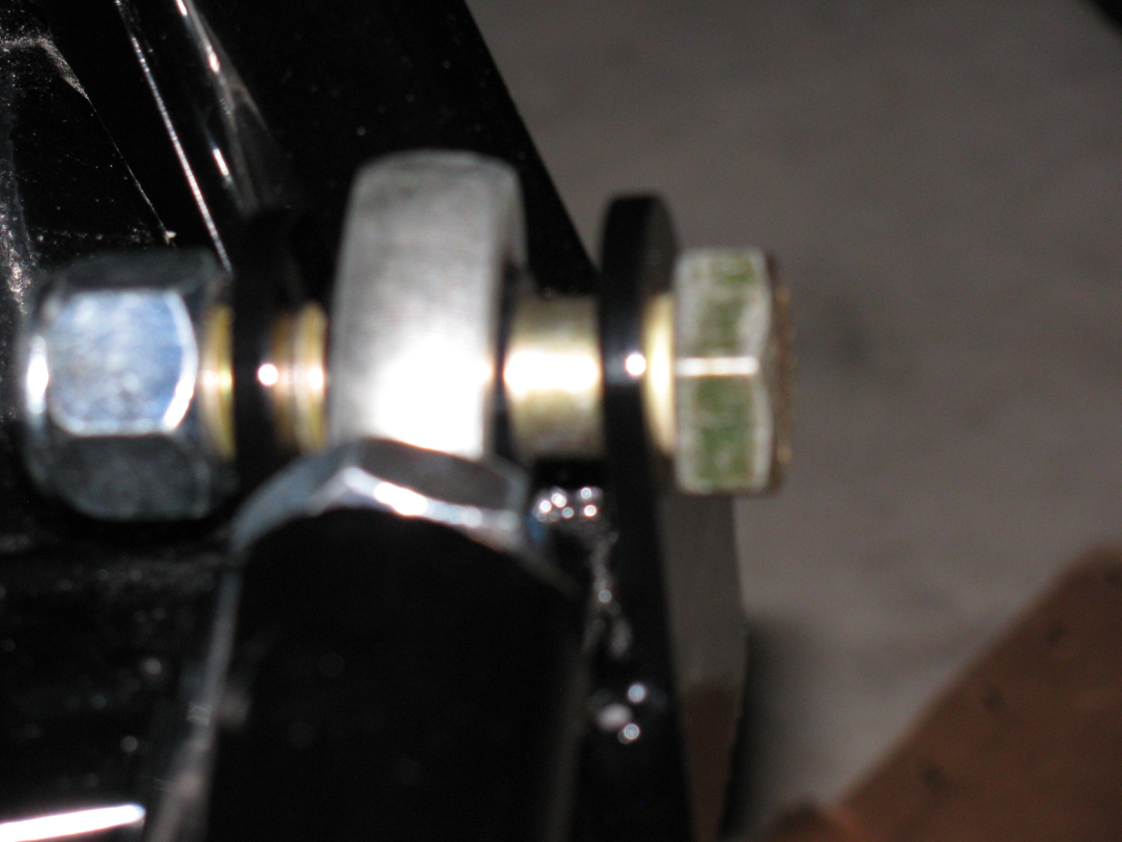
Moving back to the IRS, I received some advice from the veteran builders, and so here is what I did to the lower control arm mounts. The shims (thin black steel washers) F5R supplies are slipped into place and some adjustment is done by placing shims here and there. However, it makes more sense to limit the toe and camber adjusters so that the tweaking can be as simple as possible. By “fixing” one side of the control arm, and limiting it to one adjuster for toe and one adjuster for camber, alignment is simplified and less time consuming.
Currently, this stage is to just “eyeball” the adjustments, and continue the build process. Wheel alignments – both front and rear – may be done after the wheels and tires are mounted. (Probably can be done at the “go kart” stage, when the chassis is complete and the engine, drivetrain, electrics and brakes are installed and running.)
Here are some pictures. As this step gets closer to completion, I will add more details for future reference.


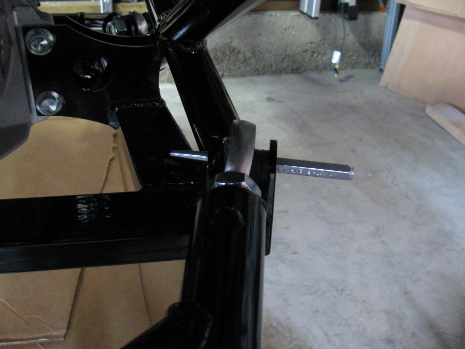
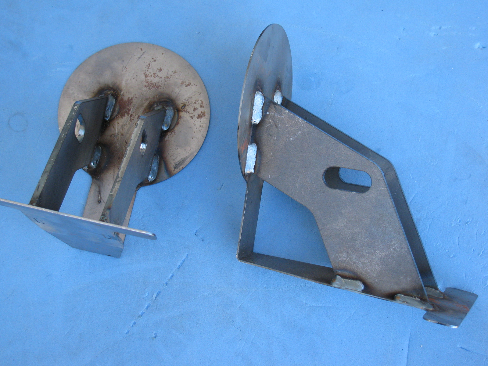
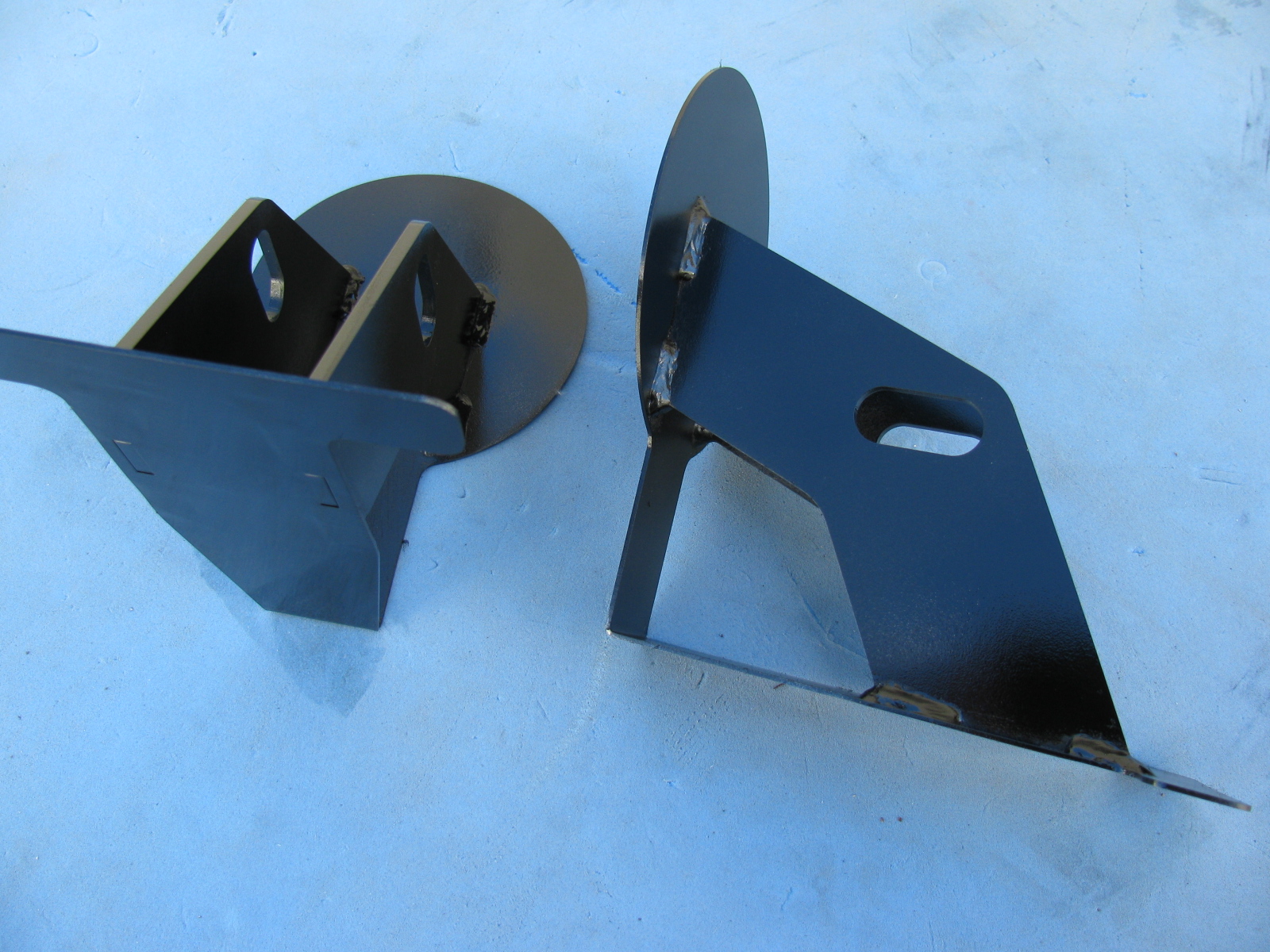
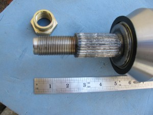
Above left: The Type 65 Coupe IRS lower control arm mounts. One shim on the front side of the mount, six shims on the side toward the rear of the car. The heim joint is threaded on so that 5/8-ths of an inch of thread are showing.
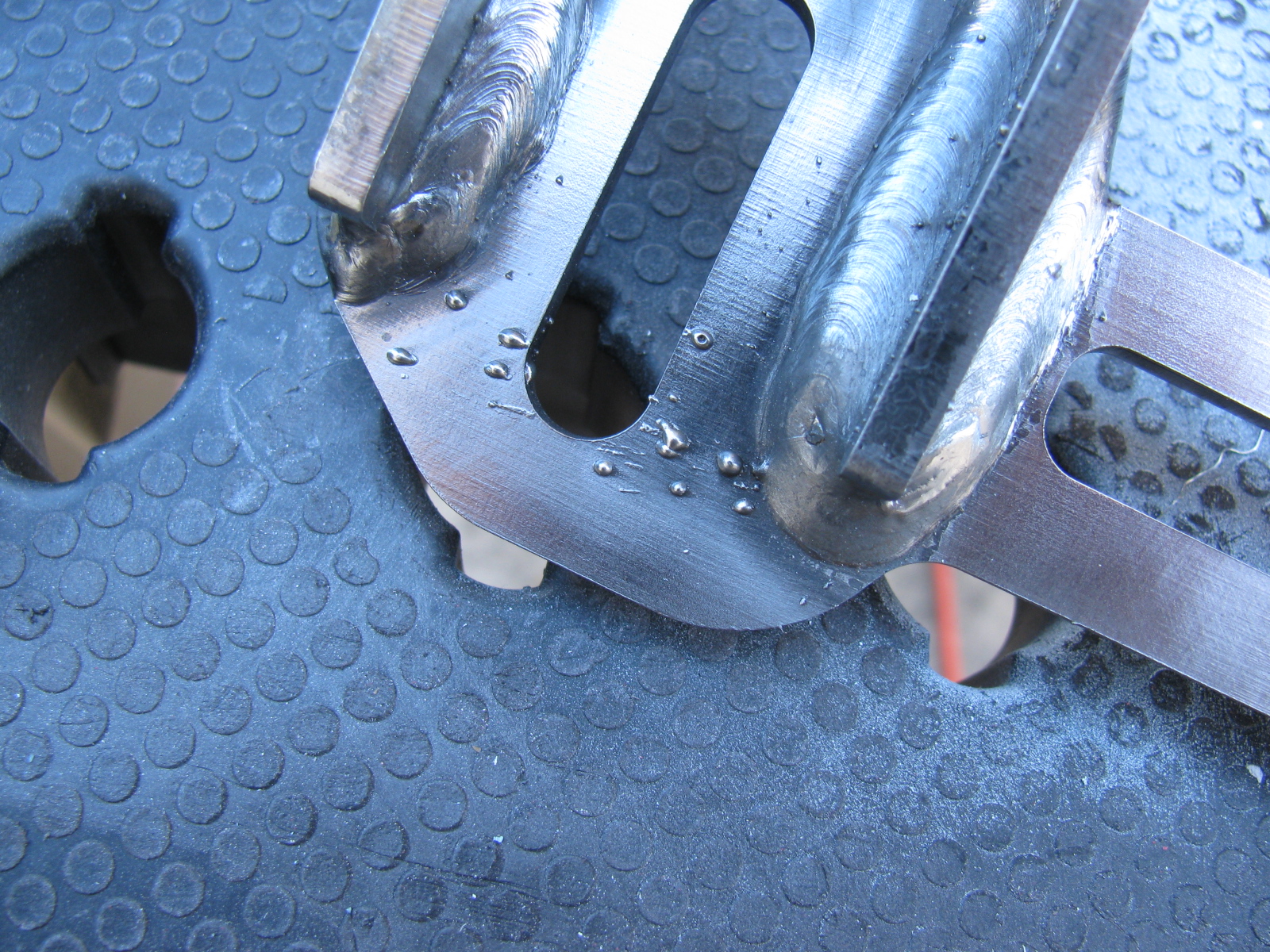
Above right: Here is the trick I use to install slippery washers, shims and spacers onto things – Use a punch or some other tool to poke through the stack of parts together, thus aligning the holes of each part. Then . . .


. . . push the fastener – and the punch – through the stack of parts. Wiggling, pushing and pulling will help. Sometimes a quick-clamp can help, too.
Maker Faire 2013 Update: Application is In!
I turned in an application for Maker Faire Bay Area 2013. Our Maker name is “Not Your Grandpa’s Ham Radio 2” and we will continue the theme my team entered last year. We will have some new projects on display, and we will bring some of the more popular items from last year. Here is a look at some of our projects from last year – as well as some other interesting and amazing things I saw last year.


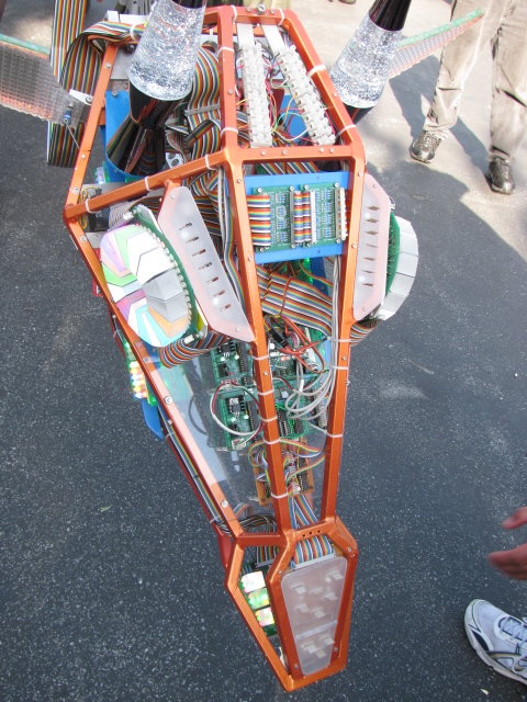
Above – One of the most interesting exhibits at Maker Faire 2012 — The Electric Giraffe named Russell – it is a scaled-up and enhanced version of a plastic model kit – it is 17 feet tall. Below left: Jeri Ellsworth, aka Circuit Girl, and her electric Key-Tar at Maker Faire 2012. Below right, Maker Alex shows us her finger tip no keyboard keyboard.


More Maker Faire 2012 images are posted on my YouTube channel.
ARRL CEO David Sumner – K1ZZ – wrote a great story on Amateur Radio and the hands-on experience this technical hobby – and free public service – provides. Click here to go to the Urgent Communications story. . . .
But – Dave did not mention what’s going on on the ham radio microwave bands. Click here to visit the San Bernardino Microwave Society (SBMS) and the 50 MHz and Up Group and the North Texas Microwave Society (NTMS) to see what we are doing on the frequencies way up there. . .
Some Body Parts, More IRS Conundrum and a New Microwave Antenna for KH6WZ
Inspired by a post on the Factory Five Racing forum and the dry and sunny weather this weekend, I decided to paint some of my body mounting parts. I am using gloss black Rust-Oleum Appliance Epoxy paint for these pieces. I have used this paint for my electronic and radio projects with good results. The paint dries very hard and is waterproof and washable, perfect for these parts.
Surface prep is easy for this paint, I scuff the surface with a 60 grit sanding disc on my random orbit sander. For the hard to reach nooks and crannies, I use a wire wheel chucked in my hand drill. Then I use liquid dish soap and water to wash off the grit and any oils. No primer is needed for this paint. Then I apply two or three light fog coats first, and then blast a thick coat for the fourth or fifth and final coat.
Here is a “before” and “after” picture of the front nose mounting hinge.

I did the same with the door hinges. Here you can see some weld splatter that will interfere with the mounting bolts, so I used a Dremel tool to grind those weld balls off.

Although many of these parts will not be seen, I do not want them to rust. Other parts will be painted in the same way, and include the door frames, the rear glass hatch hardware and the emergency brake mechanism.
Meanwhile . . .
After spending some time fiddling with the factory-supplied accelerator pedal, I decided to buy an aftermarket gas pedal instead. I ordered one of Russ Thompson’s gas pedals earlier this week from Breeze Automotive, one of the Factory Five Racing Forum supporters. I was amazed the box arrived on Thursday – that was fast!
The new gas pedal is really a machined aluminum sculpture. Pictures on this will be coming later, since I need to get the engine mounted before the gas pedal goes in.
IRS – Finished – Sort Of . . .
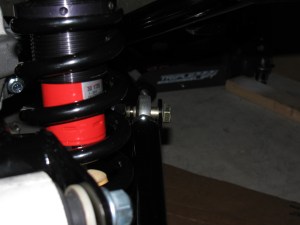
The IRS section is now fully “dry-fit” completed, and the bolts will be tightened to specs in the next work session. One thing that is putting this assembly step on hold are the mounting points for the lower control arms – see the gold color on the right of this picture? That is the mounting bolt and as you can see, there is a lot of empty space between the mounting ear and the thin washer (the manual calls them shims). This cannot be correct, and I need to find what is wrong here. . . .
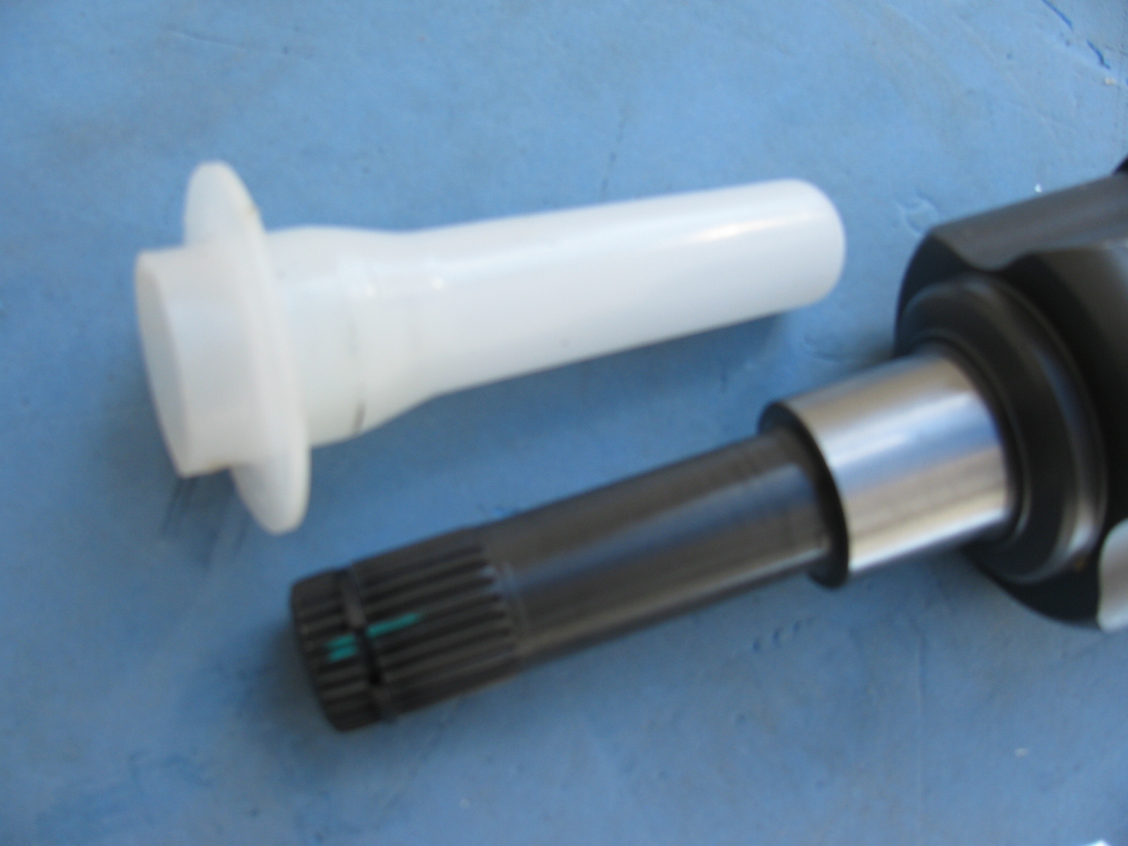
Just after I ordered my Type 65 Coupe kit, I came across a lot of posts on the forums about the IRS shafts (CV joints) coming apart. Those messages made me worry, but when my kit was shipped, the CV axles were on back-order. I called Factory Five Racing technical support, and they assured me that the problem has been fixed.
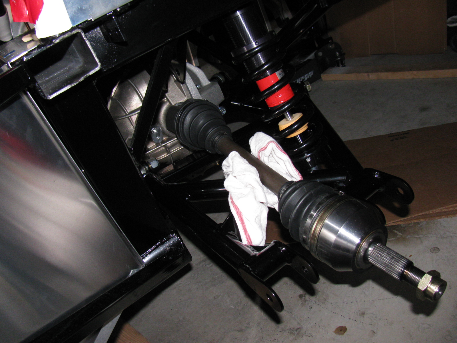
I am happy to report that my IRS system assembly went very smoothly, after the pumpkin was in place. The CV axles slipped right into the differential, and it felt just like many posts said – you can feel it lock into place. No hammering, no drama and no R- and X-rated words necessary.
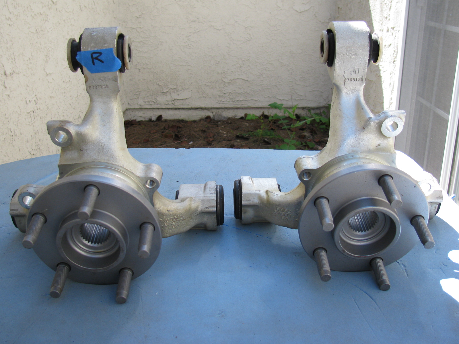
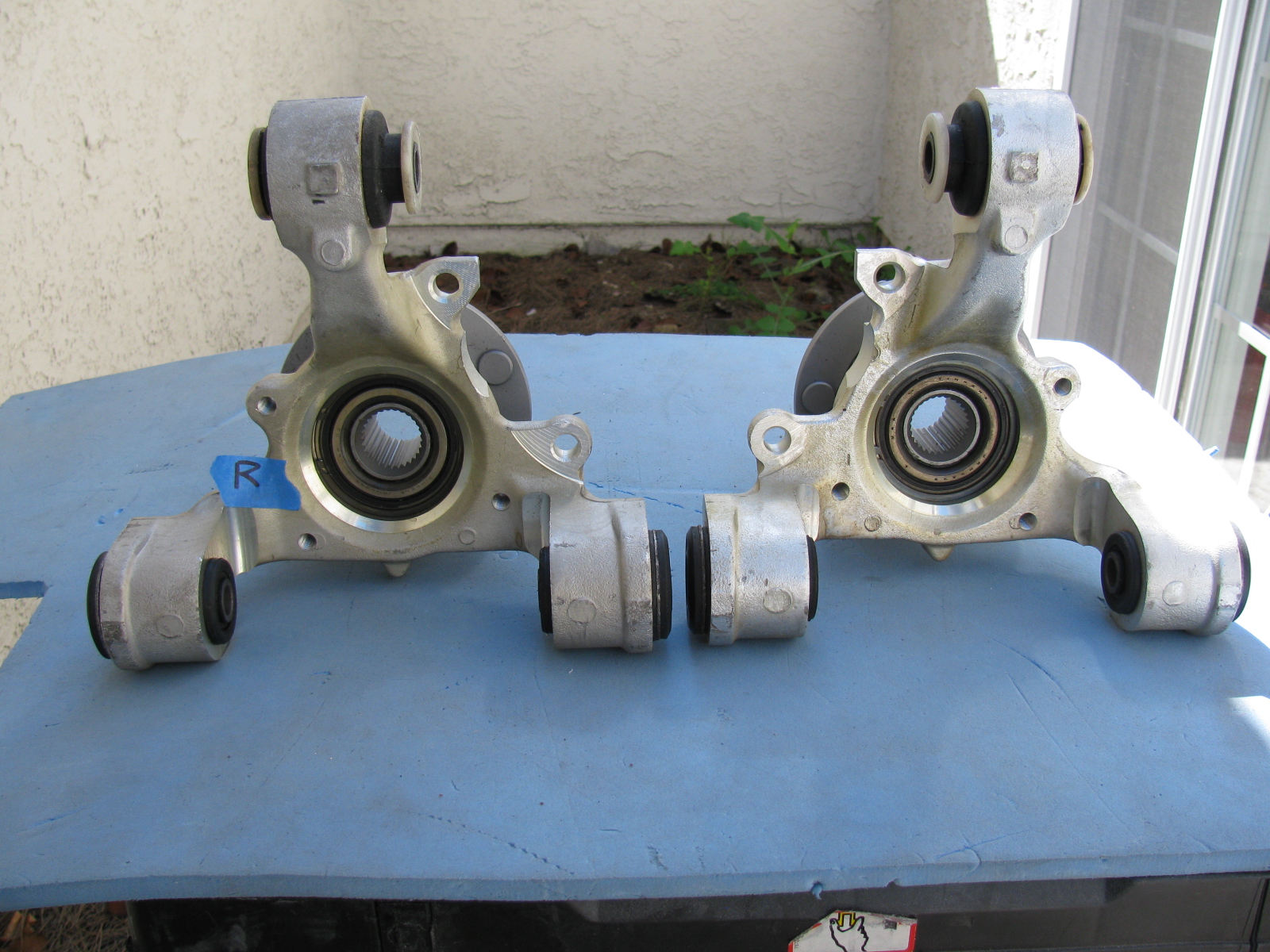
Once again, Chris comes to the rescue by posting images of the IRS knuckles and which part goes on the left side and which one goes on the right side.
Here are some additional pictures of the IRS components and system . . . . “R” is for Right side of vehicle (passenger side in the US)


Above left: The IRS upper control arm has another pair of small mounting tabs that are not mentioned in the assembly manual. No pictures are included in the manual, either. After a quick search on the Factory Five forum, I found out the smaller set of tabs point downward, and are used for quad shocks – used to minimize wheel hop during acceleration.
Give Me a Brake – Again
Now, the rear brakes are another story. Seems the Factory sent me the wrong rear brake kit. So now I have to wait for the correct parts to arrive, and then have to send the wrong parts back. . . Stay tuned for more . . .
Another Box Arrived this Week – a 10 GHz Slot Antenna
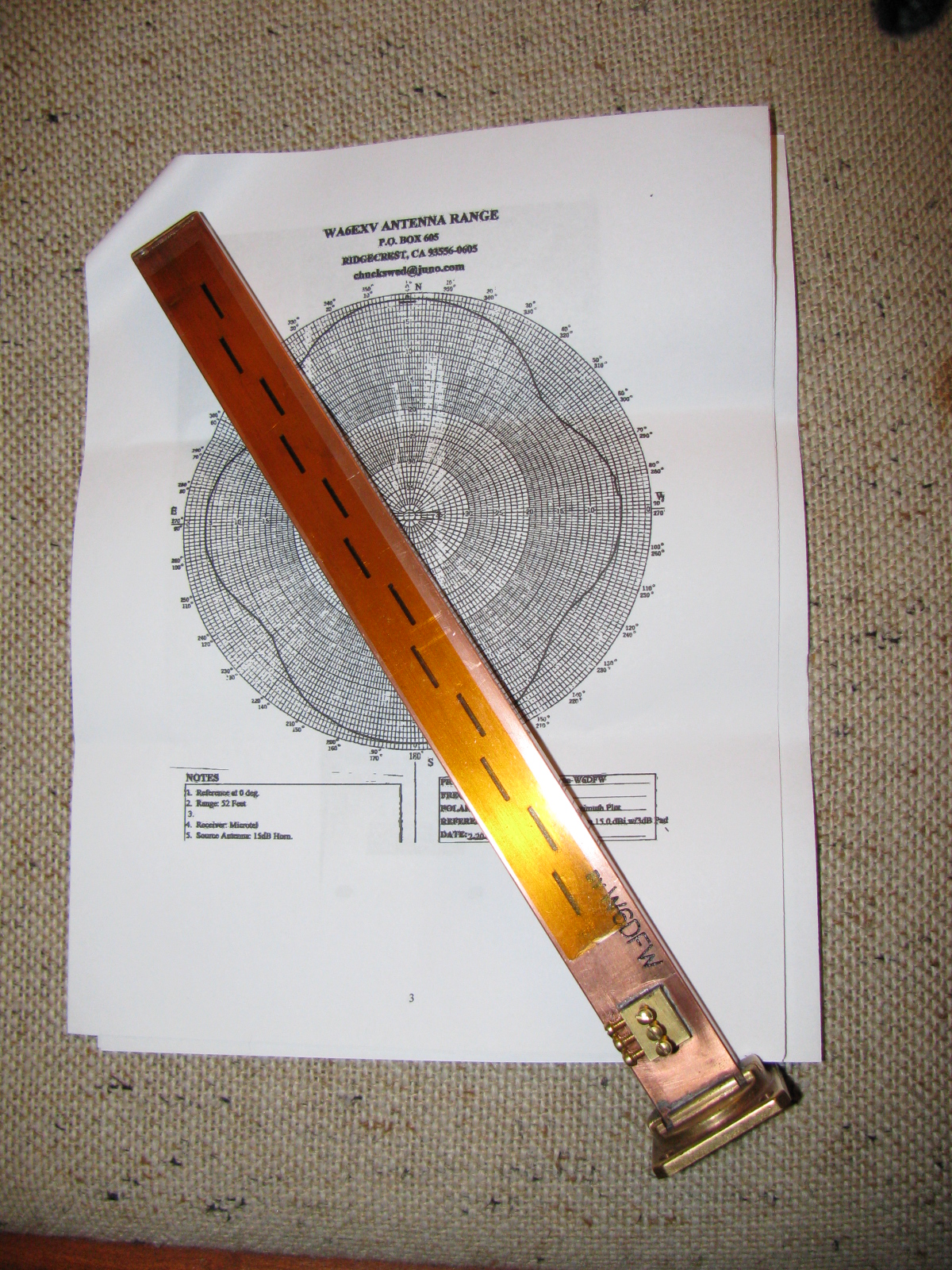
I received this nicely machined antenna for 10 GHz earlier this week. It is made by fellow SBMS member Dan, W6DFW.
Here’s a picture of this omni-directional microwave antenna. The background is the radiation pattern plotted by another SBMS member, Chuck, WA6EXV.
I am planning on using this to make my roving 10 GHz station even more portable, perhaps getting on 10 GHz FM mobile. More on this item and possible applications at station KH6WZ later.

The San Bernardino Microwave Society (SBMS) had a Christmas party this past weekend, and it was a good break from doing sheet aluminum work. The event seemed smaller this year, several of the usual suspects were not able to make it. There was lots of food to share and gifts to exchange. Happily, regular guests Mel WA6JBD and his better half, Tisza KI6DBR came and brought their usual homemade treats, including Tisza’s famous chocolate truffles, microwave dish cookies and a chocolate sculpture. This year’s sculpture was a 10GHz horn and a section of waveguide. And yes, they really do work at 10GHz. Mel measured the return loss of the horn and waveguide and reports more than 17dB or something like that – pretty respectable for an edible 10GHz antenna.
Here are some pictures of the event. . .

Where else but a ham radio Christmas party would one find a 10GHz horn and waveguide made of chocolate – that actually works

Tisza’s homemade chocolate truffles – Yum!


Gift exchange crowd
What in the World is That?
After the party wound down, I stayed to get a closer look at Dennis’ new camera. It does not look anything like a camera, but it really shouldn’t because it makes images in a whole new way and enables a whole new way to enjoy still images. I thought it looked more like a kid’s kaleidoscope, rather than a camera.
The camera and lens system optics look very simple. And that is one of the points: You do not need fancy telephoto or macro lens capability. It is done in software. There are no fancy controls or buttons, only soft pads on the rubberized parts of the case. There is a power switch, a zoom control and a shutter release. An LCD with touch screen is on the back. Here are some pictures of this new gadget.

WHAT is THAT!

The Lytro camera. At left is the lens cover, it attaches magnetically. That’s an item that will be lost immediately. Center, the camera, showing the front glass and lens. Right – a tripod adaptor.
As I mentioned on my LinkedIn update, the Lytro camera introduces a paradigm shift in the way we can look at still pictures (pun intended, sorry). At first, I thought this camera simply used some sort of image processing to “fix” images, simple things like contrast and color adjustments and maybe some image manipulation, like PhotoShop. But then Dennis said that you can change focus and “raw image” features, like zooming in – after the image is stored on your computer.
The images are not jpg or other familiar formats – but then – these are not ordinary images, either. You can actually change the depth-of-field – change the point of view of the image.
Watching some of the demos on the Lytros website made me think of scenes from the TV show “CSI:” because you can see an image captured by the camera, and you can actually zoom and move around the various places on the image, and see what else the camera captured.
Visit the Lytro website, pictures and demos and details are worth closer examination. Unfortunately, I don’t have any Lytro images to share – yet.
The Coupe Goof
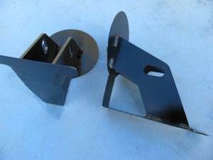
The day after the party, I went back to work on the Coupe. Something bothered me as I looked at the images and some postings of other builders. The driver’s side footbox and the front, where the pedal box mounts, looked different than mine. And I found another driver side footbox front panel in my box of aluminum parts. I looked at the part number of the “extra” footbox front (15312) on the packing slip, and noticed the description: “Driver Footbox Front Wall, Coupe Wilwood Pedals.”
Argh. Since I have the Complete Kit, it came with a Wilwood pedal box. Part of the confusion is the way Factory Five Racing packed the sheet aluminum – the major parts are held in place on the chassis and are shipped in place. This would be fine for the builders using a donor Mustang pedal box, the “Basic Kit” version.
So, I had to remove the driver side footbox front panel and replace it with the proper one. The good news is that I had all these things in place with Cleco fasteners, not rivets and silicone. And, I used the old panel as a drilling guide for the new panel. Now I have a spare sheet of aluminum I can use for – something. Hatch covers, maybe.

On the left is the wrong driver side footbox front panel. This is the one that is shipped in place on the chassis. The one on the right is the front panel for the Wilwood pedal box. Good thing I didn’t silicone and rivet that panel!

Disaster averted – the wrong footbox front panel was removed and replaced with the correct front panel for the Wilwood pedal box.