The ARRL 10GHz and Up contests are coming up soon (August 17 to 18 and September 21 to 22), so I thought I’d re-publish my article that originally appeared in The Proceedings of Microwave Update 2005.
The Harris-Farinon Model SD-108175 / 076-108687-001 solid state power amplifier (SSPA) has been seen globally on the surplus market over the last few years. This amplifier is a part of a large rack of equipment running on the traditional 24VDC, positive ground telecom power system bus.
In its original form, the amplifier is very robust and heavy, since it is rated for continuous duty, Class A operation. Figure 1 shows the unit as received. It is mostly heatsink, and the RF unit, where the microwaves are amplified, is the tiny silver box on top.
The SSPA unit (Model SD-108175) measures about 15-1/2 inches wide, 4-1/4 inches high and 10 inches deep, and weighs over 15 pounds. The little silver box (part number 076-108687-001) with SMA isolators at the input and output, is about 3 inches wide, 1 inch high and 2-1/2 inches deep.
Important: Be careful if you see these units for sale, I have seen some inaccurate descriptions of these units – for ham radio use, the only item we want is just the amplifier (076-108687-001) and not the heatsink/chassis assembly or the power supply DC-DC converter.
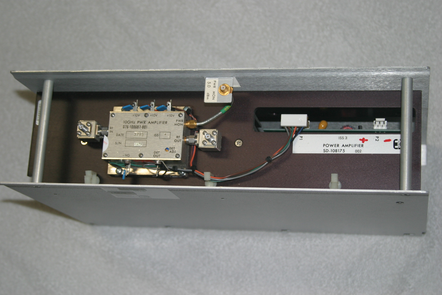
Figure 1. The Harris-Farinon 10GHz amplifier is very beefy, but it is mostly heatsink. The little silver box is where the RF is amplified.
I took the unit to Dave Glawson’s lab (WA6CGR) to see if we could integrate this SSPA into my X-band rig. It is a 1W unit, but I have several that put out as much as 3W on 10368 MHz. I purchased several of these units at a very reasonable price, and am pleased with their performance on the 10 GHz Amateur Radio band.
The terminals on the amplifier as well as the power supply PCB are marked, simplifying some of the guesswork about what-goes-where. The amplifier includes a “POWER MON” SMA female jack, which should probably be capped with a 50Ohm termination to prevent oscillations or weird things from happening while the amplifier is operating. A “DET OUT” pin is useful to verify amplifier operation.
It may be prudent to read Chuck Houghton’s article, “Above and Beyond, Microwave Stripline Retuning Procedures” on tweaking circuits before any “poking around” is done on any SHF amplifier, to prevent damage. Links to references are at the end of this article.
The first step is to power it up and verify operation in its “as-is” state. With about +17dBm (about 60mW) input, power output is about +35dBm, or a little over 3W at 10368MHz. Current consumption is about 2.6A during standby and about 3A at 10V with RF applied. Dave and I wondered whether or not we could tweak the amplifier to get more power out, so we took a look under the lid of the little silver box, see Figure 2. We decided not to tweak anything inside the tiny box.
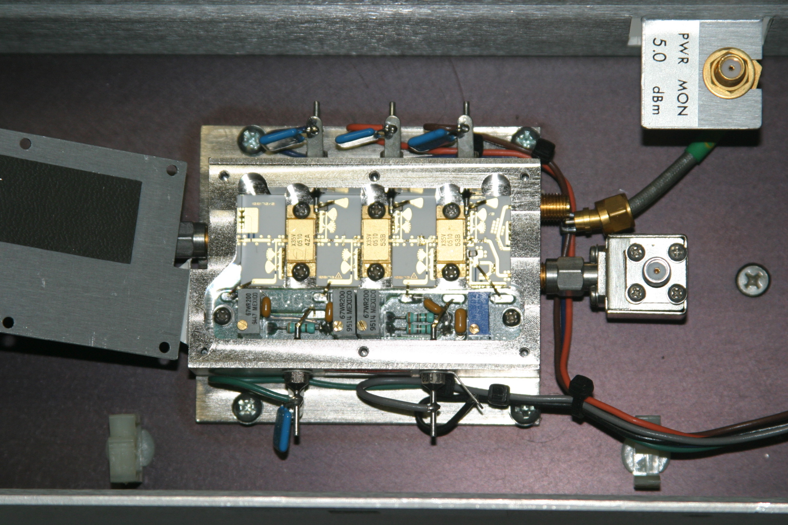
Figure 2. A peek inside the SSPA. No tuning is required to get two to three watts output on 10368MHz.
Since the amplifier passed its first tests, the next step is to re-package the unit so it would be more suitable for portable and roving operations. Certainly, a weight reduction could be done by shrinking the size of the RF module heatsink, and adding a fan or two.
Since the amplifier passed its first tests, the next step is to re-package the unit so it would be more suitable for portable and roving operations. Certainly, a weight reduction could be done by shrinking the size of the RF module heatsink, and adding a fan or two.
The DC-DC Converter
The original power supply board appears in Figure 3. A casual inspection of the unit showed that the 24V input was buck-regulated down to 12V, and then further reduced to minus 2.1V for the bias and +10V for each stage in the amplifier. The DC-DC power supply looks like it can be modified and re-used, by applying 12VDC where the brick converter has its output. However, this modification was not attempted.
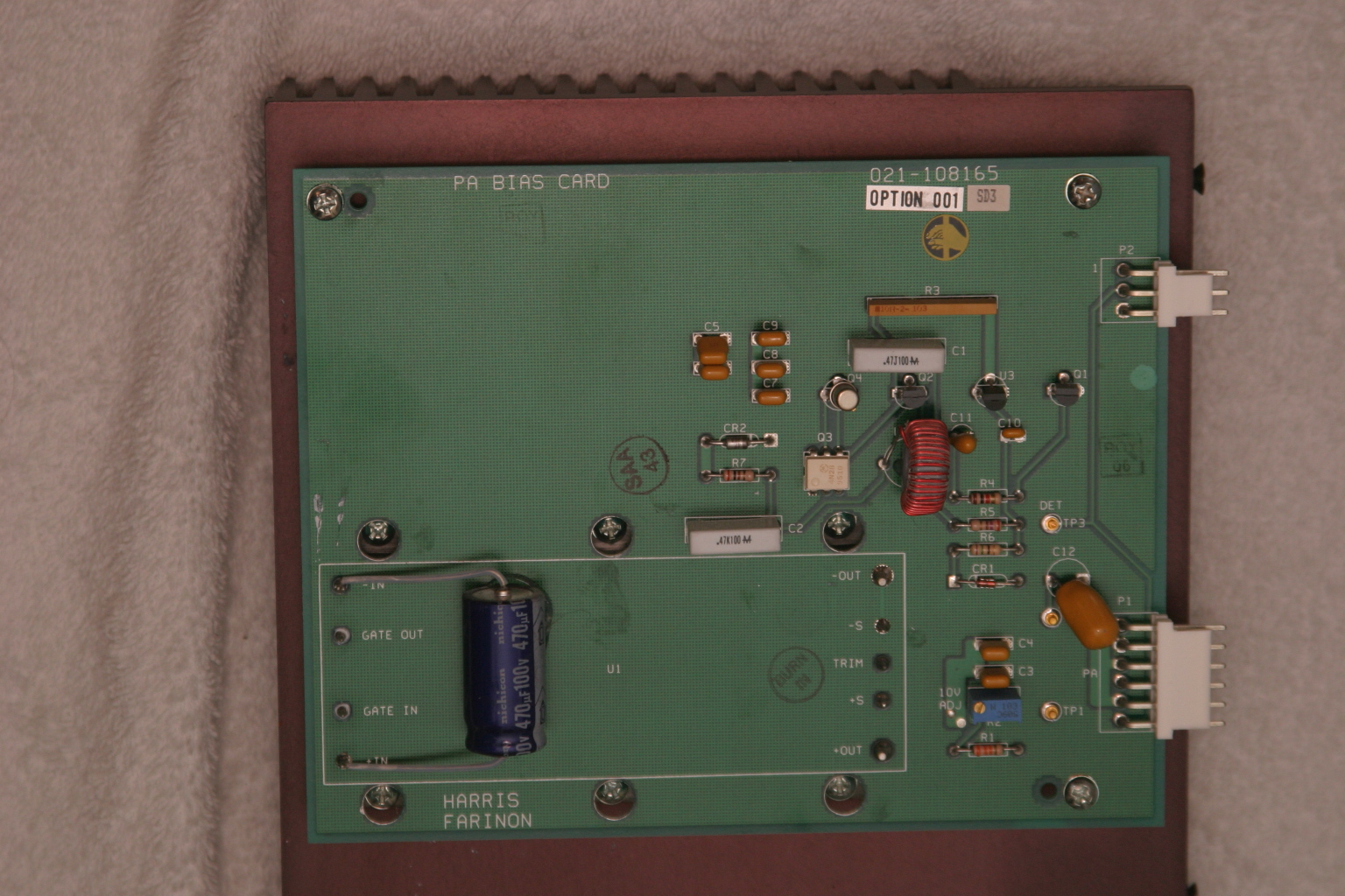
Figure 3. The DC-DC supply board. A 24V to 12V brick converter is mounted to a 14-1/4 inch by 7-1/4 inch heatsink under the PCB. The existing DC-DC converter may possibly be modified to make the unit work on 12VDC input. See text.
I thought a better, lighter, more modern power supply could be built fairly easily, and the large heatsink for the power supply could be deleted.
With Dave’s help, I made a simple DC-DC converter using a Linear Technology LT-1083 adjustable regulator and a few resistors for the +10V supply. The negative bias supply was made from a surplus 99-cent DC-DC converter. I built the power converters into separate chassis boxes, since I had them on-hand. A single box is also acceptable.
Like all FET power amplifiers, one must make sure that the minus (gate) bias supply is always connected before the supply voltage to prevent damage to the devices. I am sure there are several solutions for power-on sequencing to prevent this from happening, including relay or other switching or timing schemes. However, I chose a very simple route: I simply wired the minus voltage directly to the amplifier bias feed-thru capacitor, with no switching in-between. The plus 10V supply line is switched to the amplifier via a power relay, actuated by the sequencer. This way, whenever the rig is powered up, the minus bias voltage is “automatically” applied (it was never off in the first place), and the plus 10V is applied only when the rig is put into transmit mode.
I had a pair of 24V brushless DC motor fans in the junk box, so I am using these to blow on the heatsink. Since I have both 24V and 12V running around in my rig, I wired up a two-speed fan control using a pair of spare relay contacts. When the radio is in the receive mode, 12V is applied to the fans, reducing the noise. When the rig goes into transmit mode, 24V is applied to the fans, running them at full speed.
The final result is shown below. The amplifier is mounted in one of my 10GHz rigs, “Ms. June.” 3 The SSPA puts out 2W at the antenna port, and now measures about 4 inches by 7 inches by 1-1/2 inches, including the cooling fans. A re-labeled, surplus CB panel meter (1mA movement) connected to the DET OUT pin indicates SSPA operation. (Update: Ms. June was cannibalized for parts. However, many of her parts were used in other radios, including my latest, record-setting 10GHz transverter.)
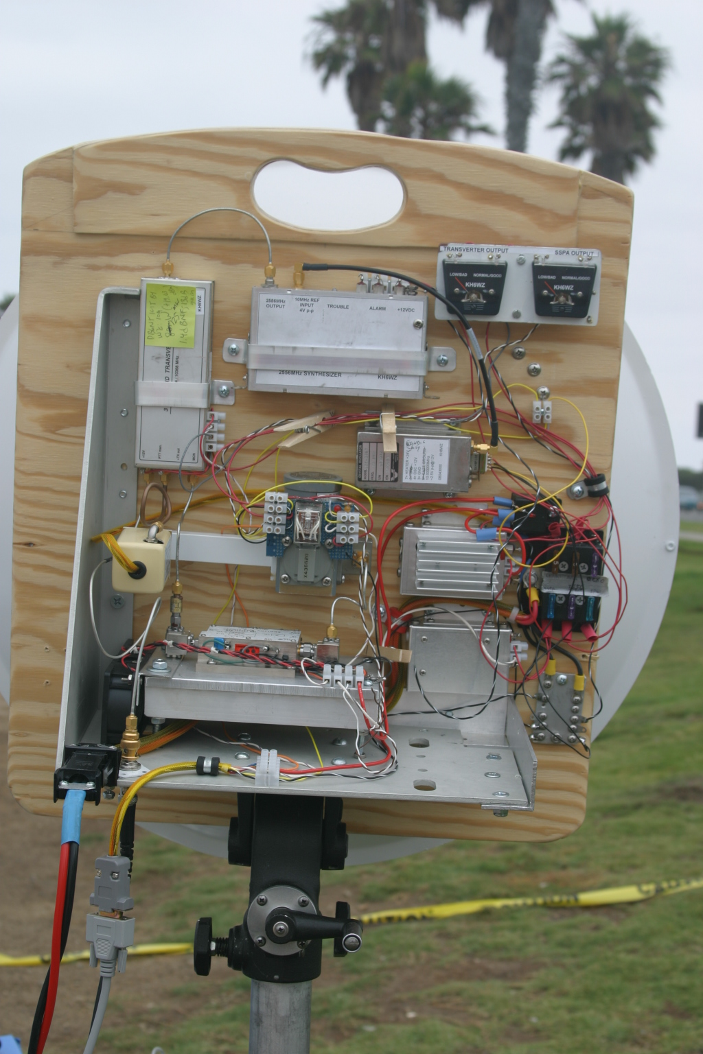
Figure 4. The Farinon SSPA installed in “Ms. June,” one of my early 10GHz rigs. Two watts appears at the waveguide port at the antenna relay in transmit. The DC-DC converters are enclosed in separate chassis boxes, and can be seen just to the right of the amplifier. A re-labeled surplus meter monitors amplifier operation.
References
1 – “Above and Beyond, Microwave Stripline Retuning Procedures,” by C. L. Houghton, WB6IGP, San Diego Microwave Group:
http://www.nitehawk.com/rasmit/mstrp_tu.html
2 – The surplus TDK DC-DC converter is described as a “5V in +/-5V DC/DC converter” at MPJA Online, as part number 1042518. This unit is under a “closeout” deal, so supplies may be limited. Go to http://www.mpja.com, and look under “Power Supplies,” “DC-DC Converters.” Their phone number is 800-652-6733, 9AM to 5PM Eastern Time, Monday through Friday. Although probably not necessary, I removed the TO-220 device from the board and re-mounted it to the metal chassis box for heat-sinking.
3 – Most of the SBMS members have names for their rigs, mainly because, as many of you know, microwave radios tend to have personalities of their own. Ms. June is my sixth 10GHz radio re-build. “Morpheus” was my first attempt, see CQ magazine for December 2003 and January 2004 for my dubious start on the microwave bands.
