Archive for the ‘RF’ Tag

Some additional information to supplement my presentation called “Building and Contesting on 10 GHz.”
This is not a complete listing of “microwave amateur radio knowledge” but it is a one-page resource to help you get started.
The first thing I would recommend is to find and join your local VHF and above ham radio club. There are clubs that focus on microwave technology and operating all over the world – find yours to meet new people, learn new things, get a rig going and join the fun!
Microwave Update (MUD)
One of the best places to meet active microwave band hams and learn more about the SHF ham bands is the Microwave Update (MUD). The event is sponsored by various clubs around the USA.
The printed papers (Proceedings) are available from the Lulu print-on-demand service.
The IF Radio

All-mode transceivers become the IF on the uWave bands
All-mode transceivers become the intermediate frequency (IF) stage in a microwave transverter system. I like to call the IF rigs the human to “transceiver interface” because this is the unit we use to tune the operating frequency, hear through the speaker and transmit audio via the microphone. Usually the IF radio also initiates the receive to transmit change-over as well.
It is important to know that IF radio performance does not affect overall performance on the microwave frequency.
In other words, fancy filtering, special ovenized oscillators and even CW or SSB filtering are not mandatory. While all those features and functions can enhance enjoyment, it’s the transverter at the microwave frequency that determines performance for the microwave station. In fact, I have two Yaesu FT-817s. One is equipped with CW filters, one is not. Sometimes, because stations often drift, the IF radio with the filter may not be able to hear the other station because the stations have drifted beyond the receiver passband. I normally bypass the filter on my IF radios.
But this is also a good thing, since it means inexpensive and even used VHF, all-mode rigs can be used.
Also remember, for transverter use, the transmit power from the IF rig is on the order of a few mW or less. So, if you are able to find, for example, an all-mode 2m rig being sold “for parts or repair” – that may be a viable candidate for an IF radio.
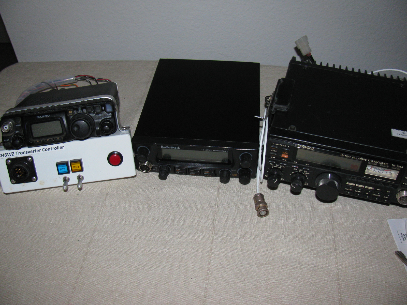
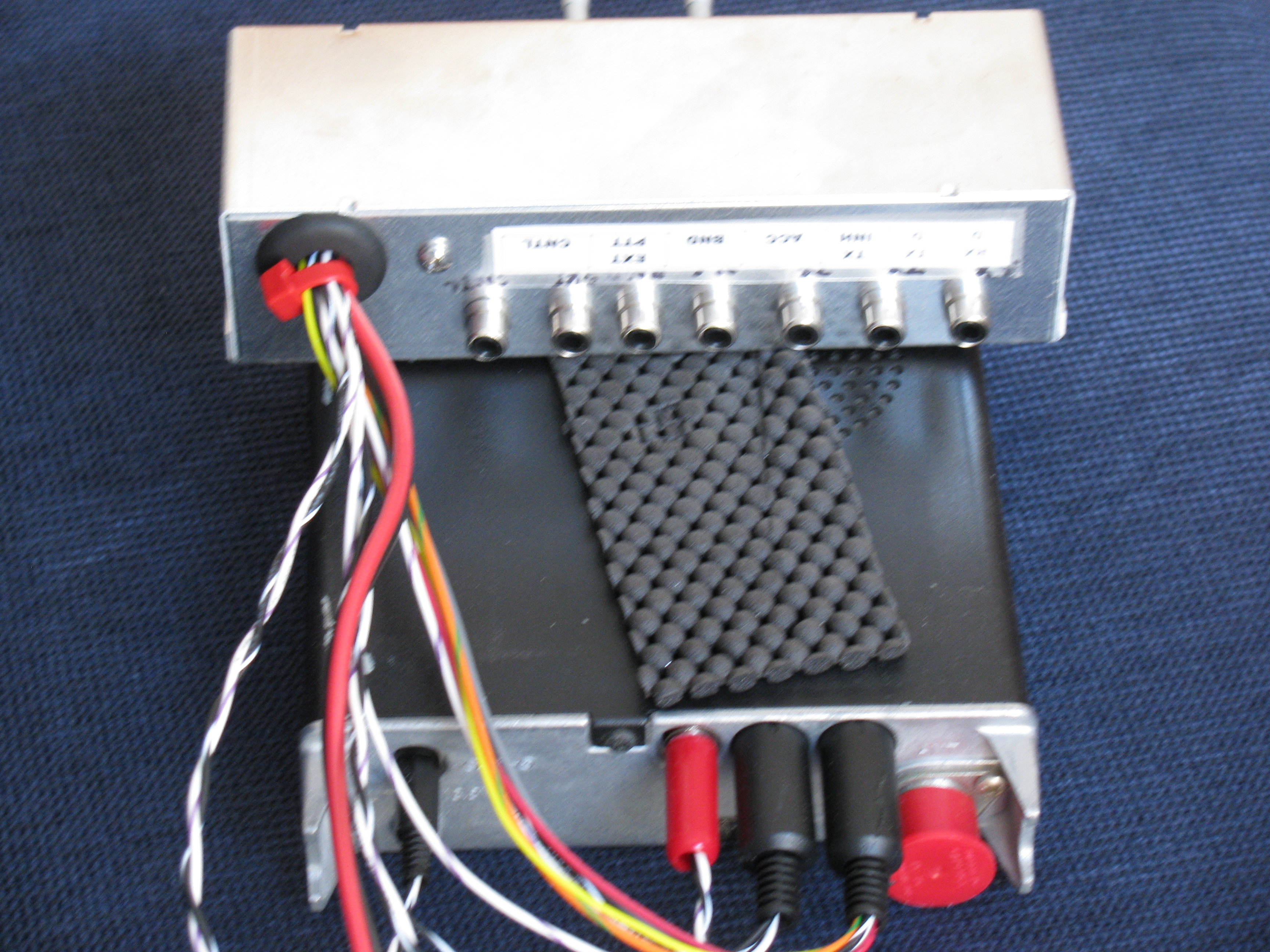
On most of my IF radios, I added a “convenience box” interface. This box converts all the interface connectors to ordinary RCA jacks. This is very handy in case my IF radio breaks: I can quickly swap any IF radio and swap it almost instantly, regardless of the IF radio model. My IF radios include a Kenwood TR-751, Yaesu FT-817, Radio Shack HTX-10, and some others.
Here is a picture of the convenience box on my FT-817 . . .

KH6WZ IF Rig with RCA Jacks

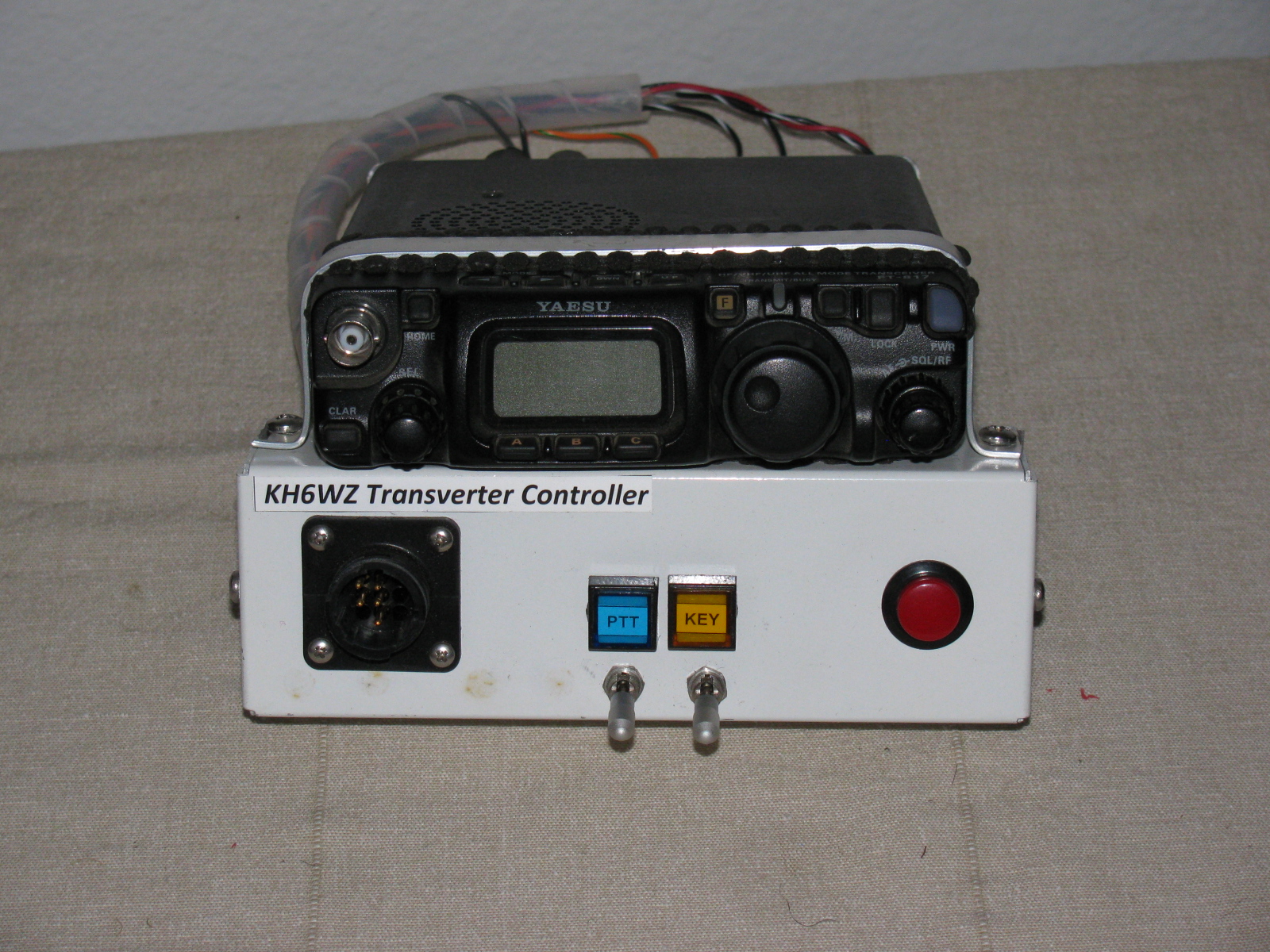
IF Radio Convenience Box – Control
The white box front panel, from left to right: Multi-pin interface jack for DC power and control. Center left: Above, blue LED for “PTT Closed” indicator. The locking toggle switch is used to lock the IF rig into transmit (PTT Lock) mode to make it ready to send a carrier/beacon tone. Center right: Above, the yellow LED indicates “Key Condition.” The locking toggle switch is closed and locked to key the transmitter after the PTT is locked into transmit. The red push button is used to send CW in case I forget to pack my key or the key breaks in the field.
Essential for Success: Accurate Reference Frequency

To help ensure successful two-way operation on the microwave bands, a stable and accurate 10 MHz Reference oscillator is essential.
This can take the form of Ovenized Crystal Oscillators (OCXO), GPS-Disciplined Oscillators or Rubidium Oscillators. All of my transverters have OCXO units that I calibrate at a friend’s lab. Once set, I can depend on being very close to the displayed frequency. One secret: I keep the reference oscillator continuously powered throughout the contest weekend.
Although some club members have rigs using a rubidium or GPS standard, my OXCO-equipped rigs are able to match those other, more sophisticated radios without any problems.
Improvement Paths
Receive

Low Noise Amplifier (LNA) for 10 GHz
Low Noise Amplifiers (LNAs) can be found as Low Noise Block converters (LNBs) for Ku-band (12 GHz to 18 GHz) satellite TV receivers. Noise figures at or better than 1dB and 20dB-plus gain can be achieved. The modifications are easy and can be done without test equipment. Chip, N6CA published an example on his webpage.
Antennas

2-ft Dish vs 6-ft Dish
I call the picture above “Dish Envy.” On the left is Dick, WB6DNX with his 2-foot prime-focus dish. On the right is Robin, WA6CDR with his 6-ft dish.
Most beginning 10 GHz ops start with discarded and usually free satellite TV offset-fed dish antennas. But 24-in. diameter prime focus dish antennas or 24- to 30-in. offset feed antennas work better. Paul Wade, W1GHZ is an excellent online “microwave antenna handbook” – a great resource for hams.
Amplifiers – SSPA, TWTA

10 GHz SSPAs
It is amazing what one can find on eBay and other online auction sites.
High power amplifiers – Solid State Amplifiers (SSPA) and Traveling Wave Tube Amplifiers (TWTA) as well as other materiel for the microwave bands such as waveguide, SMA, Type-N and other connectors and assemblies are becoming available to just about anyone.
As mentioned briefly in the presentation, you must be careful when bidding or buying an amplifier for the 10 GHz ham bands, since some non-ham band amps may not be easy or may be impossible to convert to the 10 GHz ham allocation.
However, there are also many 10 GHz amplifiers that can be re-tuned (“snowflake tuning”) or used as-is. The term snow flaking is used when describing the tuning of microwave amplifiers or other surplus items. A step-by-step article about snow-flaking a surplus amplifier for 10 GHz is posted on the San Bernardino Microwave Society (SBMS) website. See “10 GHz Qualcomm Modification Notes” and “Modifying the Qualcomm 1W Ku-Band PA for use on 3.4, 5.7 or 10.3 GHz.”
When snow-flaking, a small wooden stick with a tiny speck of copper foil is touched and moved around the traces of an RF section while monitoring RF power. Watching for peaks, the small probe is removed, and a piece of copper foil is soldered in that location.
It is tedious but can be fun and rewarding when the job is completed and you have more power on the X-band.
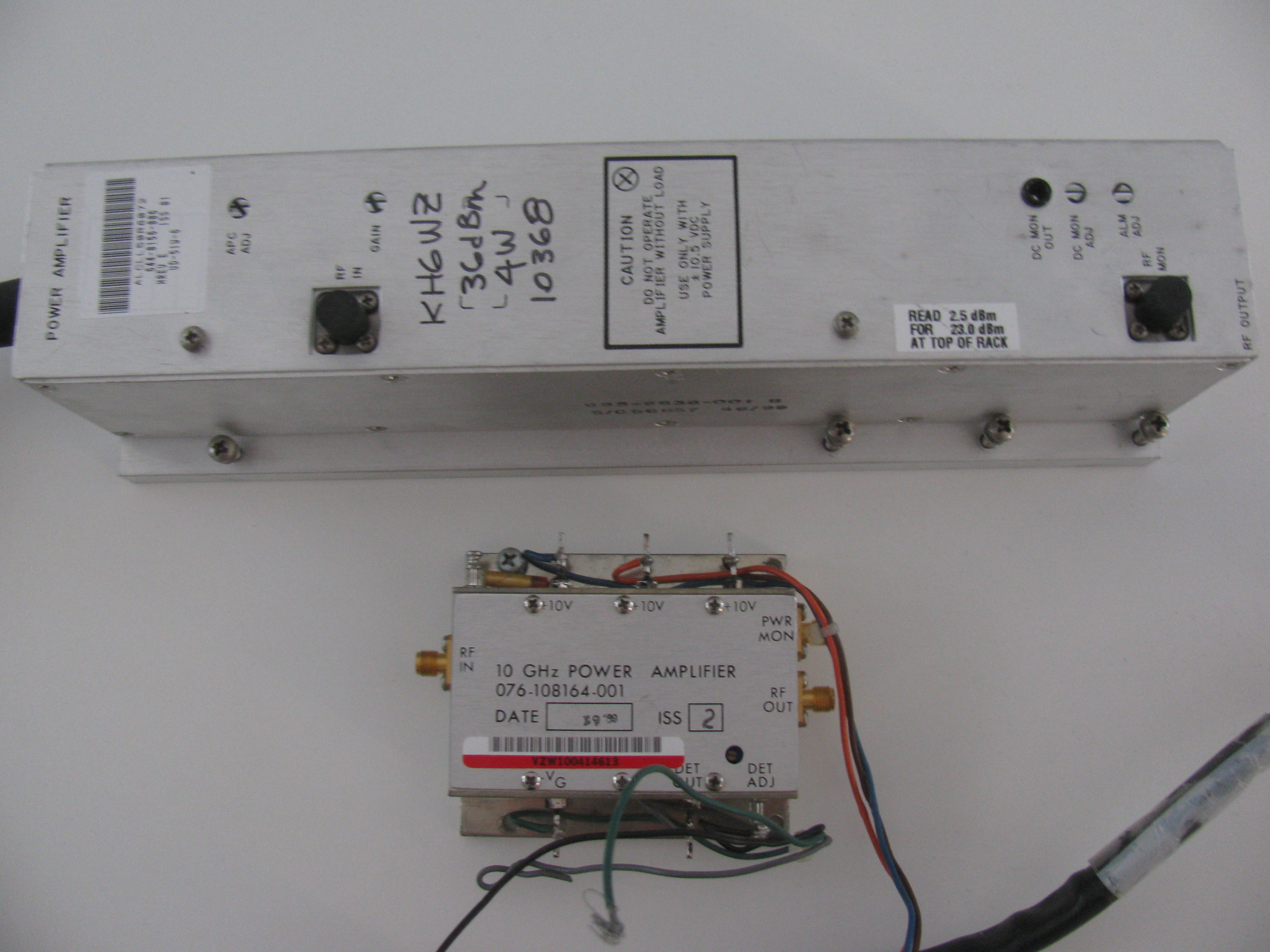
An excellent example of a small amplifier often found on eBay can be used without modification is the Harris-Farinon Model SD-108175 / 076-108687-001 solid state power amplifier (SSPA). I have several of these in use, and the power varies from about one watt to three watts on 10368 MHz.
See “Harris-Farinon 10 GHz Amplifier for Amateur Radio Use” in the References section below.
The good news is that many microwave ham bands over-lap the commercial or other non-ham service allocations (such as Wi-Fi, Bluetooth and Industrial, Scientific, Medical [ISM]), and amplifiers intended for these services can often be used as-is without modifications to the RF section. No tuning necessary.
In any case, all amplifiers will require a power supply (various voltages), power supply sequencing and high power transmit/receive changeover to integrate into a “beginner system.”
Sequencers: Protect Your Investment

Sequencer Demo at Maker Faire
When moving to higher than “driver power” (milliwatts), it is important to protect the receiver and amplifier circuits by delaying the time between receive and transmit. The delay needed is only a few milliseconds, enough time to allow the relay contacts to close and settle before the change from receive to transmit happens.
A sequencer automates switching various stages in this specific order:
- Antenna relay
- Transverter enable
- Power amplifier enable
- Transmit enable
The order is reversed when going from TX to RX.
In my Maker Faire display, pictured above, the W6PQL 4-Event Sequencer is used to drive a large Type-N relay (for T/R) and three high current power relays used to turn on the transverter support functions. It is available as a kit from the W6PQL website.
I have also built and use several sequencers based on Chip N6CA’s “Time Delay Generator” circuit, presented in many years of the ARRL Handbook (1997 and others).
I hope my presentation inspires more hams to try something different. There are many developments and new technologies to explore in ham radio, let’s continue the century-old Ham Radio Tradition in the 21st century style and remind people ham radio is still relevant today!
References and Resources
I am an SBMS member. Join us!
The San Bernardino Microwave Society (SBMS)
50 MHz and Up Group
North Texas Microwave Society
The World Above 1000MHz – Peter Day, G3PHO
USA Amateur Radio Frequency Allocations – The tiny bottom right corner of the chart
Microwave Update: The best technical conference to meet other active VHF-plus ops and learn more!
Technical Papers & Software from the San Diego Microwave Group – including modification information for Surplus Qualcomm boards made available to the ham community
10 GHz Qualcomm Modification Notes, by Dale Clement, AF1T – SBMS
Modifying the Qualcomm 1W Ku-Band PA for use on 3.4, 5.7 or 10.3 GHz by Kerry Banke N6IZW
“Harris-Farinon 10 GHz, 2W Amplifier for Amateur Radio Use” (Originally appeared in The Proceedings of Microwave Update 2005)
DUBUS – the serious magazine for VHF and up amateur radio
A List of VHF and Up Contest Locations in Southern California
Down East Microwave – Transverters and other kits and parts
Kuhne Electronic – Transverters and other kits and parts
Microwave Ham Radio Tom Williams WA1MBA
Jim Klitzing W6PQL – Sequencers, accessories, amplifiers and general information
Mike King KM0T – Great website with lots of pictures and construction notes
Wayne Yoshida KH6WZ – Various topics on ham radio, Maker Faire, and Factory Five Racing Type 65 Coupe
Read my LinkedIn profile article about ham radio and my career
Note: If you wish to connect with me, click the “Connect” button (not “Follow”) and enter a personalized connect request. I do not respond to the default connect requests.


Advice when soldering de KH6WZ
October 3 and 4: Maker Faire® San Diego!

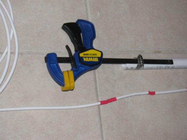
Maker Faire San Diego is October 3 and 4, 2015, from 10 AM to 6 PM at Balboa Park. Our “Not Your Grandpa’s Ham Radio” theme will feature some new projects as well as some of the old, but popular demonstrations from previous Maker Faire events. Pictured below is a project under construction, I hope to have it completed for this event. It is a homemade 1090 MHz collinear (vertical) antenna that will be part of an air traffic control monitoring station using a software defined radio (SDR).

October 15 to 18: Microwave Update (MUD)!

Microwave Update, or MUD, is a yearly technical conference for amateur radio experimenters making, modifying, hacking, building, testing and using the 1,000 MHz and up radio bands. Participants from all over the world gather at these events to share information about operating techniques, radio propagation and radio station equipment. One aspect of this event is the buying, selling and trading of surplus parts and assemblies for these frequency bands, since some items may be difficult to procure in some areas. But perhaps the best thing about MUD is socializing and making new friends from all over the world to discuss common interests and goals.
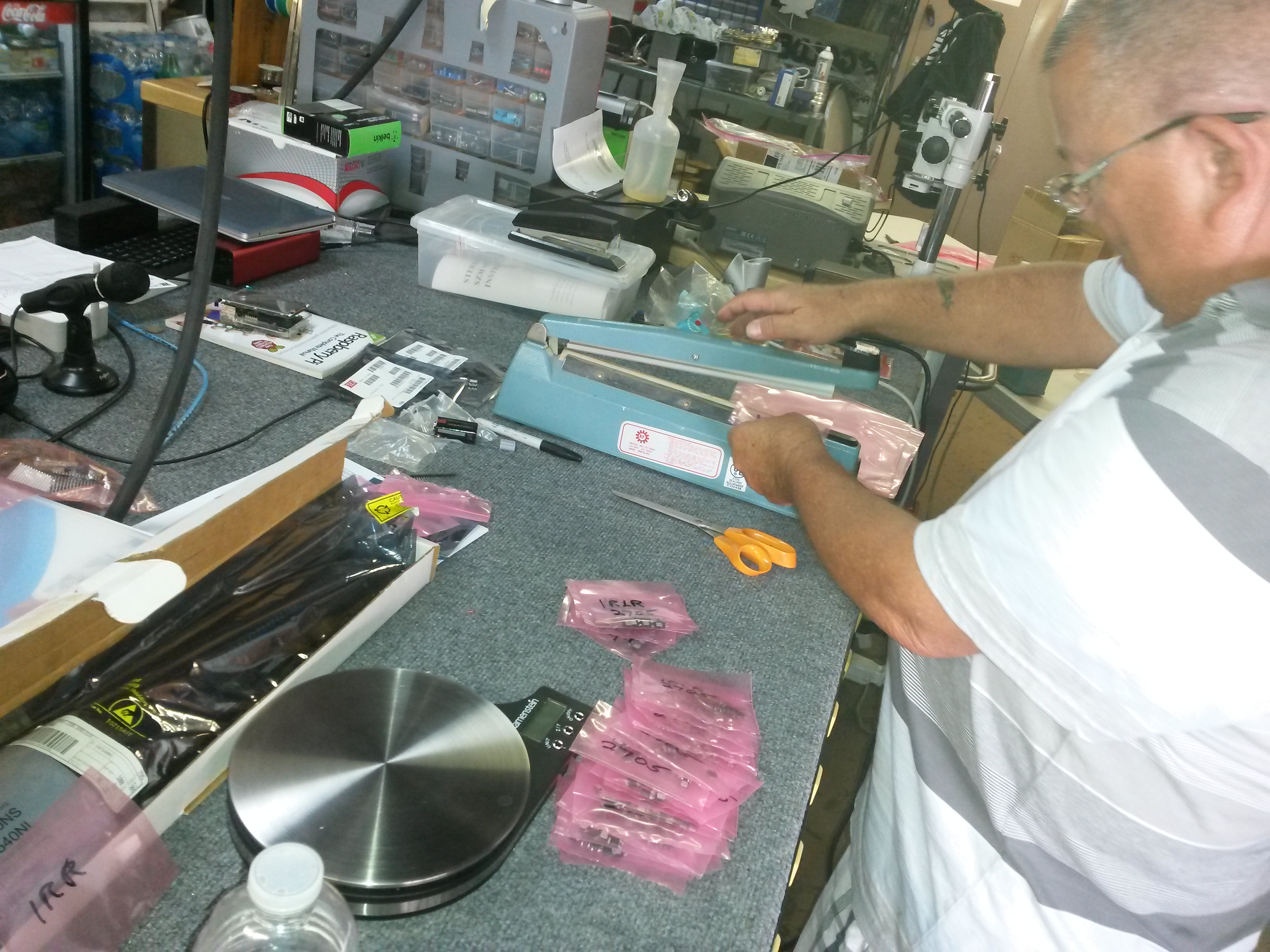
Preparations for the San Diego MUD are still under way. Last weekend, a few San Bernardino Microwave Society (SBMS) members gathered at Dave’s lab to sort and package some prize and give-away items for the event.


Left to right: Dave WA6CGR, Rein W6SZ, Pat N6RMJ and Jim KK6MXP sorting and packing some microwave frequency prizes and give-ways.
I hope to see you at any or both of these events!
The ARRL 10GHz and Up contests are coming up soon (August 17 to 18 and September 21 to 22), so I thought I’d re-publish my article that originally appeared in The Proceedings of Microwave Update 2005.
The Harris-Farinon Model SD-108175 / 076-108687-001 solid state power amplifier (SSPA) has been seen globally on the surplus market over the last few years. This amplifier is a part of a large rack of equipment running on the traditional 24VDC, positive ground telecom power system bus.
In its original form, the amplifier is very robust and heavy, since it is rated for continuous duty, Class A operation. Figure 1 shows the unit as received. It is mostly heatsink, and the RF unit, where the microwaves are amplified, is the tiny silver box on top.
The SSPA unit (Model SD-108175) measures about 15-1/2 inches wide, 4-1/4 inches high and 10 inches deep, and weighs over 15 pounds. The little silver box (part number 076-108687-001) with SMA isolators at the input and output, is about 3 inches wide, 1 inch high and 2-1/2 inches deep.
Important: Be careful if you see these units for sale, I have seen some inaccurate descriptions of these units – for ham radio use, the only item we want is just the amplifier (076-108687-001) and not the heatsink/chassis assembly or the power supply DC-DC converter.

Figure 1. The Harris-Farinon 10GHz amplifier is very beefy, but it is mostly heatsink. The little silver box is where the RF is amplified.
I took the unit to Dave Glawson’s lab (WA6CGR) to see if we could integrate this SSPA into my X-band rig. It is a 1W unit, but I have several that put out as much as 3W on 10368 MHz. I purchased several of these units at a very reasonable price, and am pleased with their performance on the 10 GHz Amateur Radio band.
The terminals on the amplifier as well as the power supply PCB are marked, simplifying some of the guesswork about what-goes-where. The amplifier includes a “POWER MON” SMA female jack, which should probably be capped with a 50Ohm termination to prevent oscillations or weird things from happening while the amplifier is operating. A “DET OUT” pin is useful to verify amplifier operation.
It may be prudent to read Chuck Houghton’s article, “Above and Beyond, Microwave Stripline Retuning Procedures” on tweaking circuits before any “poking around” is done on any SHF amplifier, to prevent damage. Links to references are at the end of this article.
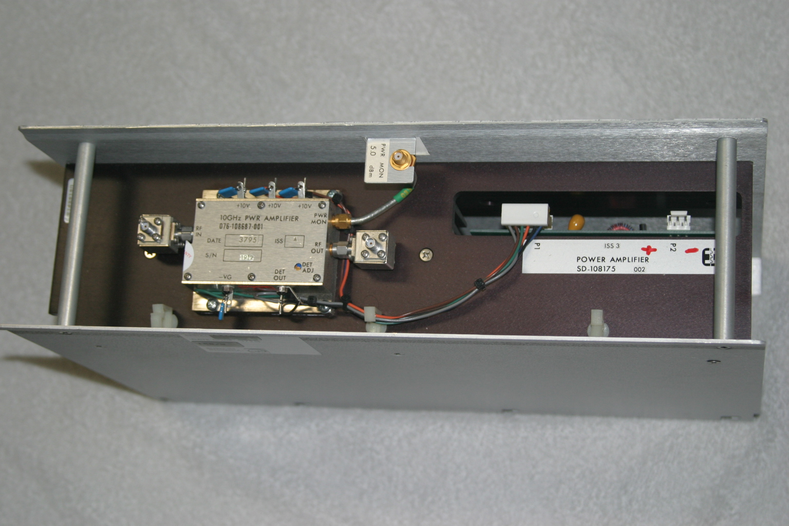
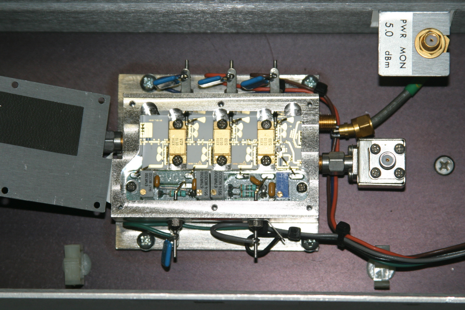
The first step is to power it up and verify operation in its “as-is” state. With about +17dBm (about 60mW) input, power output is about +35dBm, or a little over 3W at 10368MHz. Current consumption is about 2.6A during standby and about 3A at 10V with RF applied. Dave and I wondered whether or not we could tweak the amplifier to get more power out, so we took a look under the lid of the little silver box, see Figure 2. We decided not to tweak anything inside the tiny box.

Figure 2. A peek inside the SSPA. No tuning is required to get two to three watts output on 10368MHz.
Since the amplifier passed its first tests, the next step is to re-package the unit so it would be more suitable for portable and roving operations. Certainly, a weight reduction could be done by shrinking the size of the RF module heatsink, and adding a fan or two.
Since the amplifier passed its first tests, the next step is to re-package the unit so it would be more suitable for portable and roving operations. Certainly, a weight reduction could be done by shrinking the size of the RF module heatsink, and adding a fan or two.
The DC-DC Converter
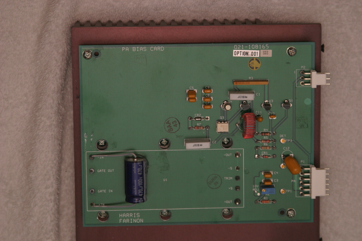
The original power supply board appears in Figure 3. A casual inspection of the unit showed that the 24V input was buck-regulated down to 12V, and then further reduced to minus 2.1V for the bias and +10V for each stage in the amplifier. The DC-DC power supply looks like it can be modified and re-used, by applying 12VDC where the brick converter has its output. However, this modification was not attempted.

Figure 3. The DC-DC supply board. A 24V to 12V brick converter is mounted to a 14-1/4 inch by 7-1/4 inch heatsink under the PCB. The existing DC-DC converter may possibly be modified to make the unit work on 12VDC input. See text.
I thought a better, lighter, more modern power supply could be built fairly easily, and the large heatsink for the power supply could be deleted.
With Dave’s help, I made a simple DC-DC converter using a Linear Technology LT-1083 adjustable regulator and a few resistors for the +10V supply. The negative bias supply was made from a surplus 99-cent DC-DC converter. I built the power converters into separate chassis boxes, since I had them on-hand. A single box is also acceptable.
Like all FET power amplifiers, one must make sure that the minus (gate) bias supply is always connected before the supply voltage to prevent damage to the devices. I am sure there are several solutions for power-on sequencing to prevent this from happening, including relay or other switching or timing schemes. However, I chose a very simple route: I simply wired the minus voltage directly to the amplifier bias feed-thru capacitor, with no switching in-between. The plus 10V supply line is switched to the amplifier via a power relay, actuated by the sequencer. This way, whenever the rig is powered up, the minus bias voltage is “automatically” applied (it was never off in the first place), and the plus 10V is applied only when the rig is put into transmit mode.
I had a pair of 24V brushless DC motor fans in the junk box, so I am using these to blow on the heatsink. Since I have both 24V and 12V running around in my rig, I wired up a two-speed fan control using a pair of spare relay contacts. When the radio is in the receive mode, 12V is applied to the fans, reducing the noise. When the rig goes into transmit mode, 24V is applied to the fans, running them at full speed.
The final result is shown below. The amplifier is mounted in one of my 10GHz rigs, “Ms. June.” 3 The SSPA puts out 2W at the antenna port, and now measures about 4 inches by 7 inches by 1-1/2 inches, including the cooling fans. A re-labeled, surplus CB panel meter (1mA movement) connected to the DET OUT pin indicates SSPA operation. (Update: Ms. June was cannibalized for parts. However, many of her parts were used in other radios, including my latest, record-setting 10GHz transverter.)

Figure 4. The Farinon SSPA installed in “Ms. June,” one of my early 10GHz rigs. Two watts appears at the waveguide port at the antenna relay in transmit. The DC-DC converters are enclosed in separate chassis boxes, and can be seen just to the right of the amplifier. A re-labeled surplus meter monitors amplifier operation.
References
1 – “Above and Beyond, Microwave Stripline Retuning Procedures,” by C. L. Houghton, WB6IGP, San Diego Microwave Group:
http://www.nitehawk.com/rasmit/mstrp_tu.html
2 – The surplus TDK DC-DC converter is described as a “5V in +/-5V DC/DC converter” at MPJA Online, as part number 1042518. This unit is under a “closeout” deal, so supplies may be limited. Go to http://www.mpja.com, and look under “Power Supplies,” “DC-DC Converters.” Their phone number is 800-652-6733, 9AM to 5PM Eastern Time, Monday through Friday. Although probably not necessary, I removed the TO-220 device from the board and re-mounted it to the metal chassis box for heat-sinking.
3 – Most of the SBMS members have names for their rigs, mainly because, as many of you know, microwave radios tend to have personalities of their own. Ms. June is my sixth 10GHz radio re-build. “Morpheus” was my first attempt, see CQ magazine for December 2003 and January 2004 for my dubious start on the microwave bands.

Maker Walt discussing something fascinating with Jeri Ellsworth, aka “Circuit Girl.” Photo by Tony KC6QHP
Here is a report on the 2013 Maker Faire by Tony Long (KC6QHP):
Another great Maker Faire is in the books, amateur microwave radio was well represented!
Thanks to the coordination efforts of Wayne KH6WZ, Brian W6BY, the 50 MHz and Up Group, the SBMS, and UC Davis, the “Not Your Grandpa’s Ham Radio 2” booth at the Maker Faire was a great success.
This year we shared a booth with UC Davis whose impressive student projects ranged from a radar demonstration, to video processing, audio sequencing, and mechatronics. Along with that, we had a 10/24 GHz SDR setup courtesy of Dennis W6DQ (on a big screen courtesy of Brian), some of Brian’s homebrew gear, Walt’s EM field demos and transceivers, and some of my stuff including a 10 GHz radio and beacon.
LA Times says that about 165,000 people were expected to attend this year, so at a minimum 10,000 people passed by our booth. Our raspy voices are an indicator that a great deal of talking was done! I personally interacted with a number of people who are really interested in amateur microwave radio and if even a fraction of them get involved or raise general awareness, I think it is a success.
Walt’s demos, owing in part to their elegant simplicity and visual nature attracted a lot of attention and interest. On Sunday night he took them to a post-fair get-together with the who’s who of the hardware hacking scene (Jeri Ellsworth, Ben Heckendorn, Diana Eng, Alan Yates and many many others). All were impressed!
Something I see very encouraging in the “maker” scene is a real interest in RF. This crowd includes a good deal of embedded systems engineers, talented software people, etc. There’s a real opportunity to make connections with this crowd and get more activity on the microwave bands.
As Software Defined Radios decrease in cost and become more open source, I predict massive interest in RF and likely in the microwave bands because of their large bandwidths. While they may not be interested in SSB mountaintop to mountaintop contesting (there will be those who are certainly), an increase in use of our bands will only help to further the cause of maintaining our spectrum to help further the state of the art.
I posted a gallery of pictures on Flickr: http://goo.gl/cAy3p
Tony KC6QHP”
Thanks for the report, Tony!