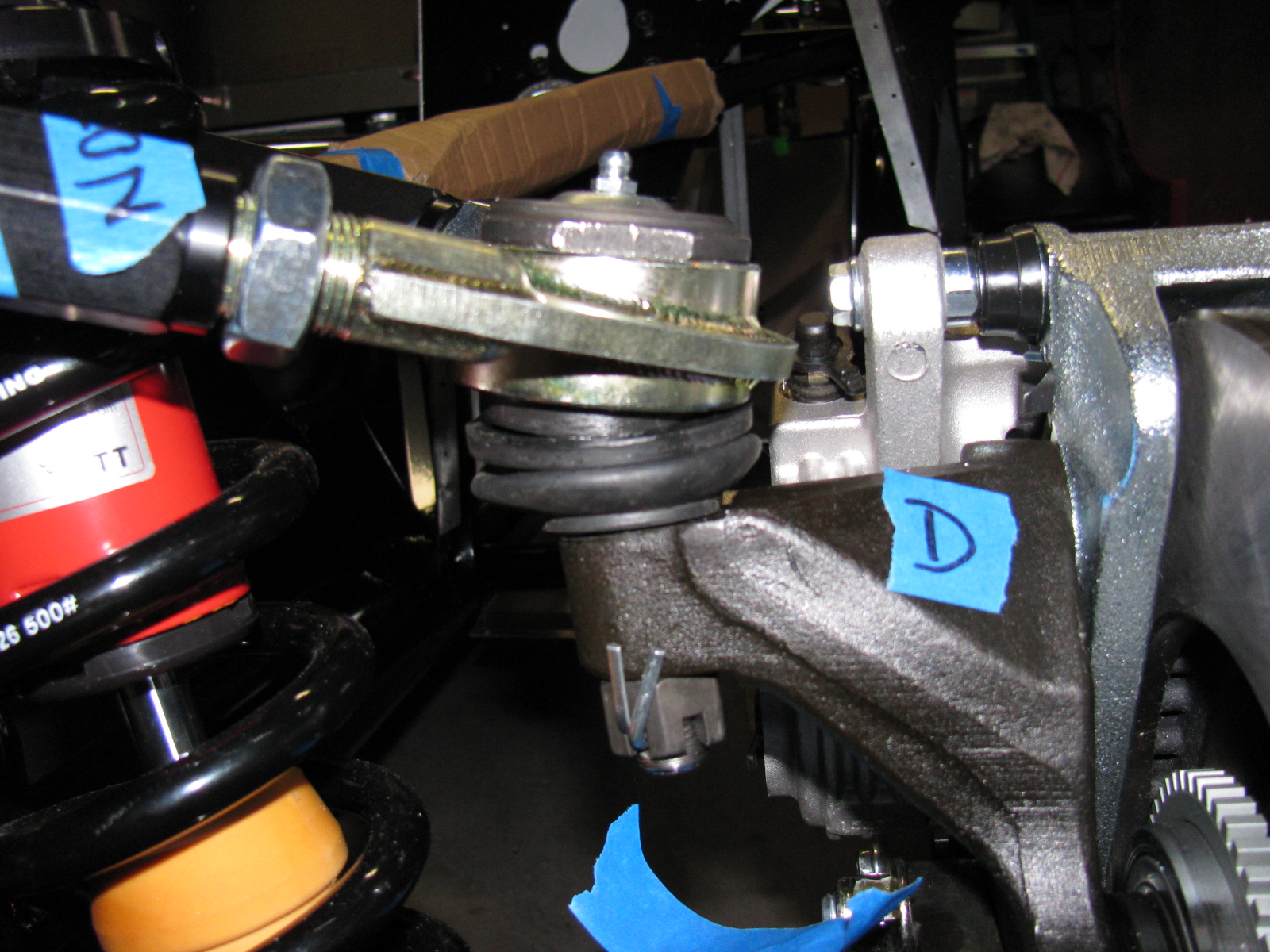
The front IFS is still not right, and the responses from the forums and the directions are confirmed by Jason at Factory Five Racing. Now the difficult task involves more un-building and hoping parts are not damaged. The ball joint on the passenger side needs to be removed and the upper A-arm top plate has to be flipped over. This is a direct result of an error in the Factory Five Racing Type 65 Coupe manual (revision 3E, July 2011) on pages 60 and 61 and 63 and 64.
The manual says to install the ball joint into the upper control arm to make “a left and a right.” I did this, and now must dis-assemble one of the ball joints. A new upper control arm is more than $200, so this is a costly error if I am not able to correct this.
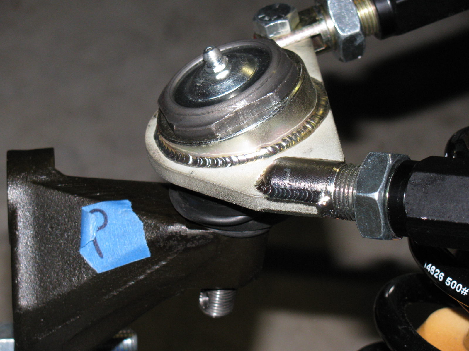
The correct orientation is shown on the driver’s side of the suspension. The passenger side is incorrect. This assembly is difficult to describe in words, so it is best shown with pictures.
Here is the driver side showing the upper control arm and the ball joint mount on the plate – see the wedge-shaped, “thicker” end at the apex of the triangular plate? This is correct.


This is the passenger side upper control arm. See the thicker wedge-shape on the opposite side of the apex? This is incorrect (wrong).


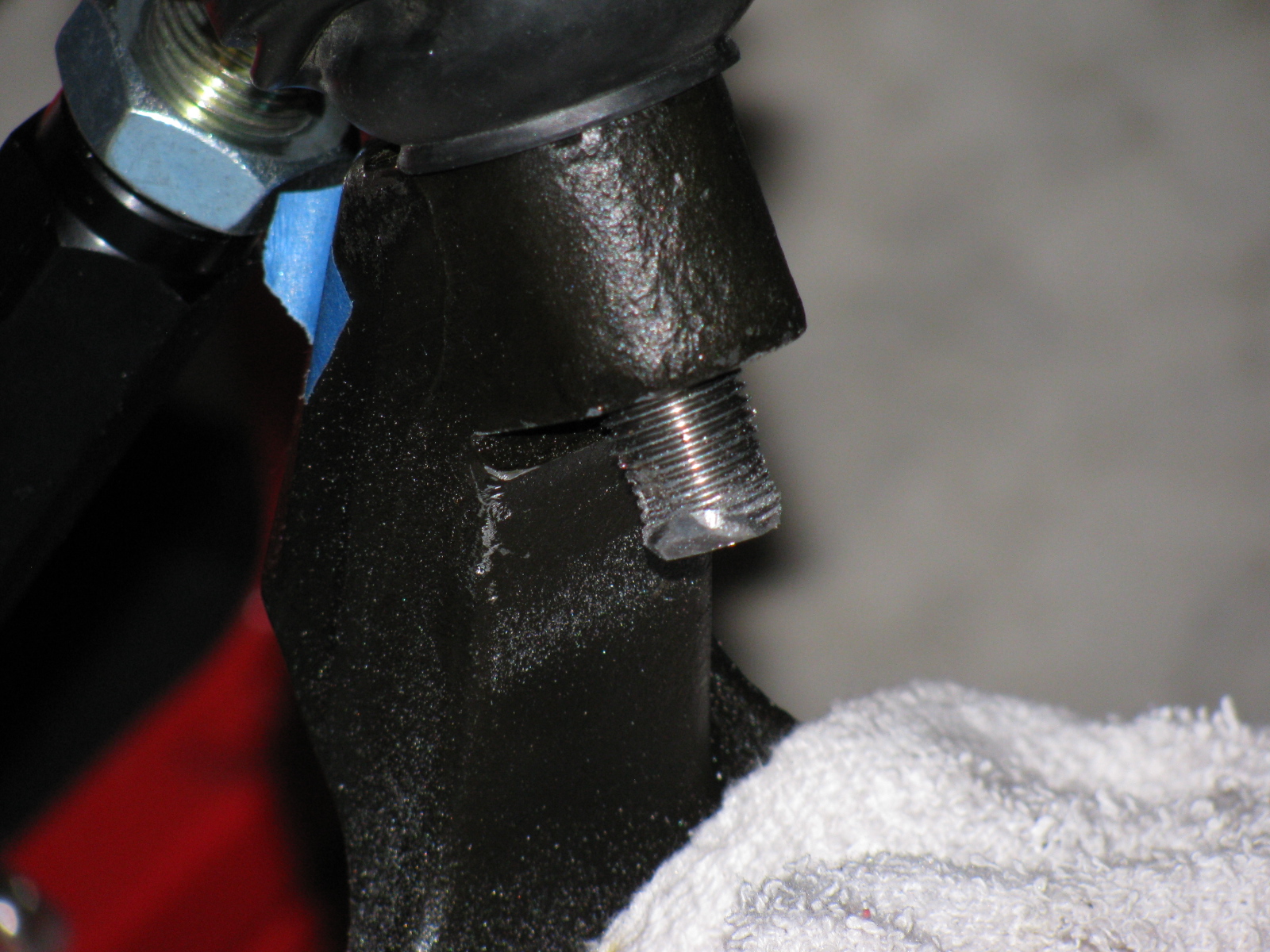
I dis-assembled most of the front suspension to get to this ball joint. However, the ball joint fits into the spindle via a tapered hole. . . meaning that some force must be applied to remove the ball joint stem from the spindle. I started by tapping – then pounding – with my plastic hammer, since I did not want to damage anything. No good. I changed to a scrap of oak and my ball-peen hammer and hit it hard for several minutes. Still no good. I got rid of the piece of wood and really slammed with the ball-peen hammer. Finally, the stem popped loose.
Of course, this created a mushroom on the ball joint stem, and it would not come out of the hole. I filed around the mushroom and finally separated the ball joint from the spindle. I should be able to file or grind the stem so the ball joint can be re-used.

Mushroom on the stem!
Removing the ball joint requires dis-assembly with 450 degrees F (since I used Permatex medium strength thread locker blue), a vise and a big wrench with lots of grip and torque.
I tried several times, but my vise just isn’t gripping the ball joint properly, it slips off. I need a bigger vise and a torch for this. My bench vise is too small.
Cutting the Dash
Since I could not remove the ball joint, I decided to move to another part of my project – cutting the dashboard in half. This is a popular modification that will increase access into the area between the dashboard and the firewall. This area will soon be stuffed with wiring and air conditioner ducting, so the dashboard had to be cut sooner or later.
I wondered how this was done, should I leave a “lip” on one of the sections so I can patch the panels together? Or do I just slice along the fold? What is the safest way to do this with my power jig saw?
It turned out to be easier than I thought. Here are some pictures of the cutting operation . . .

I used some duct tape and a wood scrap to hold the dashboard in place for the cut. My trusty Makita power jig saw did the trick.

I will use a piece of aluminum angle stock to mend the two sections together.
I may make a new dashboard front panel, especially since the original one has several things wrong. For example, I ordered the “modern gauges” option. There is no mention that the modern gauges are smaller than the vintage gauges. The dashboard comes with cut-outs for the larger gauges, and a triangular-shaped adapter plate for the smaller gauges. Also, the steering column hole is in the wrong place, as mentioned in a previous posting. If I knew this was going to happen, I would have ordered a plain, non-drilled dashboard – so if you are planning your order – consider asking for an un-cut, un-drilled dashboard and make custom cut-outs where you want them.
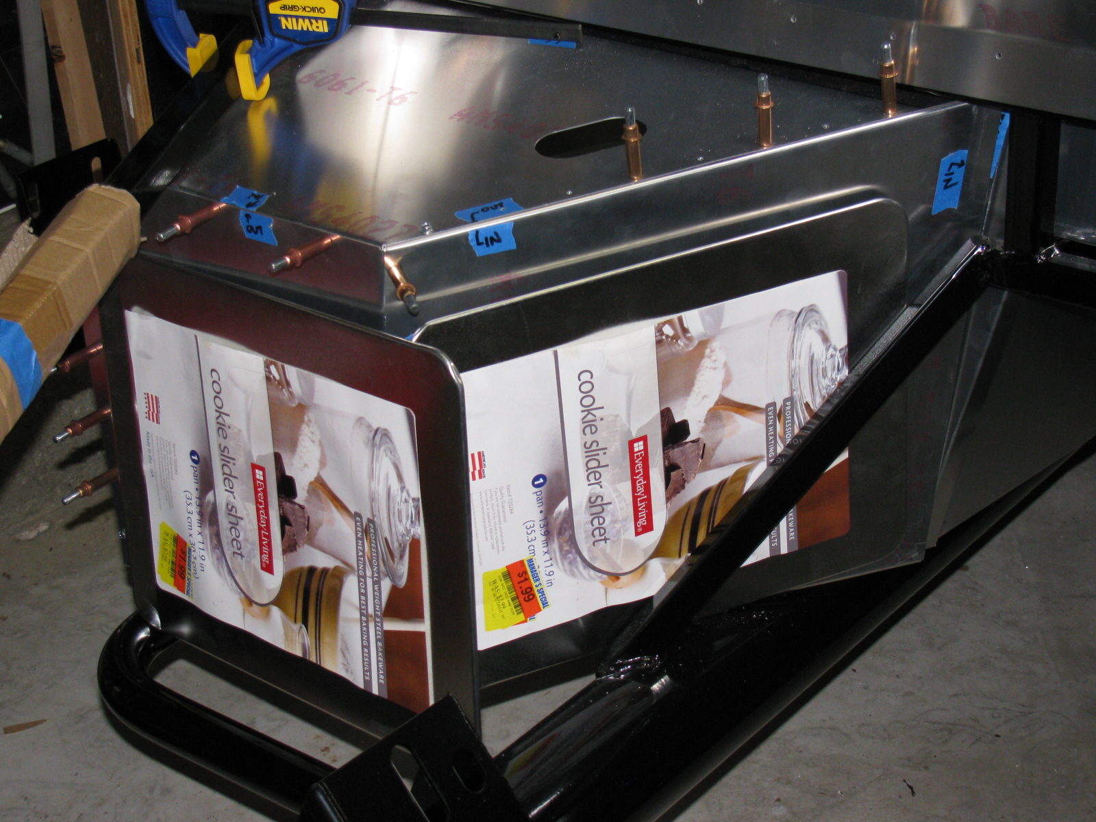
Cookie Sheet Heat Shields
A few weeks ago, I found these cookie sheets in the close-out bin at the grocery store. They have nicely rolled edges and they happen to be almost the right size for the footboxes.


The amazing part about these cookie sheets is the angle at one end – it exactly matches the angle at the back of the driver-side footbox. I will mount them with 8-32 machine screws, spacers and locking nuts. I will also add a layer of insulation (Cool-It mat) between the heat shield and the footbox panels.
I am no longer sure if I want to use the Rust-Oleum BBQ paint for my firewall and other panels. I did a paint test this weekend, and the paint is quite soft, and scratches easily.
The Battery Mounting Plate
After noticing how soft that BBQ paint is, I decided to do some more paint testing. This is the battery mounting plate. It is made of steel, and it is already starting to rust. So I decided I should paint this part and the other steel items soon.

I used Rustoleum Appliance Epoxy paint for this test. This is my standard paint for radio and electronics projects. The finish is very hard and glossy, the cured surface is washable and no primer is needed. However, it is not meant for heat, the maximum temperature is 200 degrees F.
I prep the surface by scuffing the surface with 80- or 150-grit sandpaper on a random orbit sander, followed by a dish soap and water wash. I apply the paint in three or four very light fog coats and the surface becomes slightly textured. I may go with this paint, if I can find a suitable color. The last time I looked at spray paints, this appliance finish comes in white, almond and black. Too bad it does not come in silver or gray.
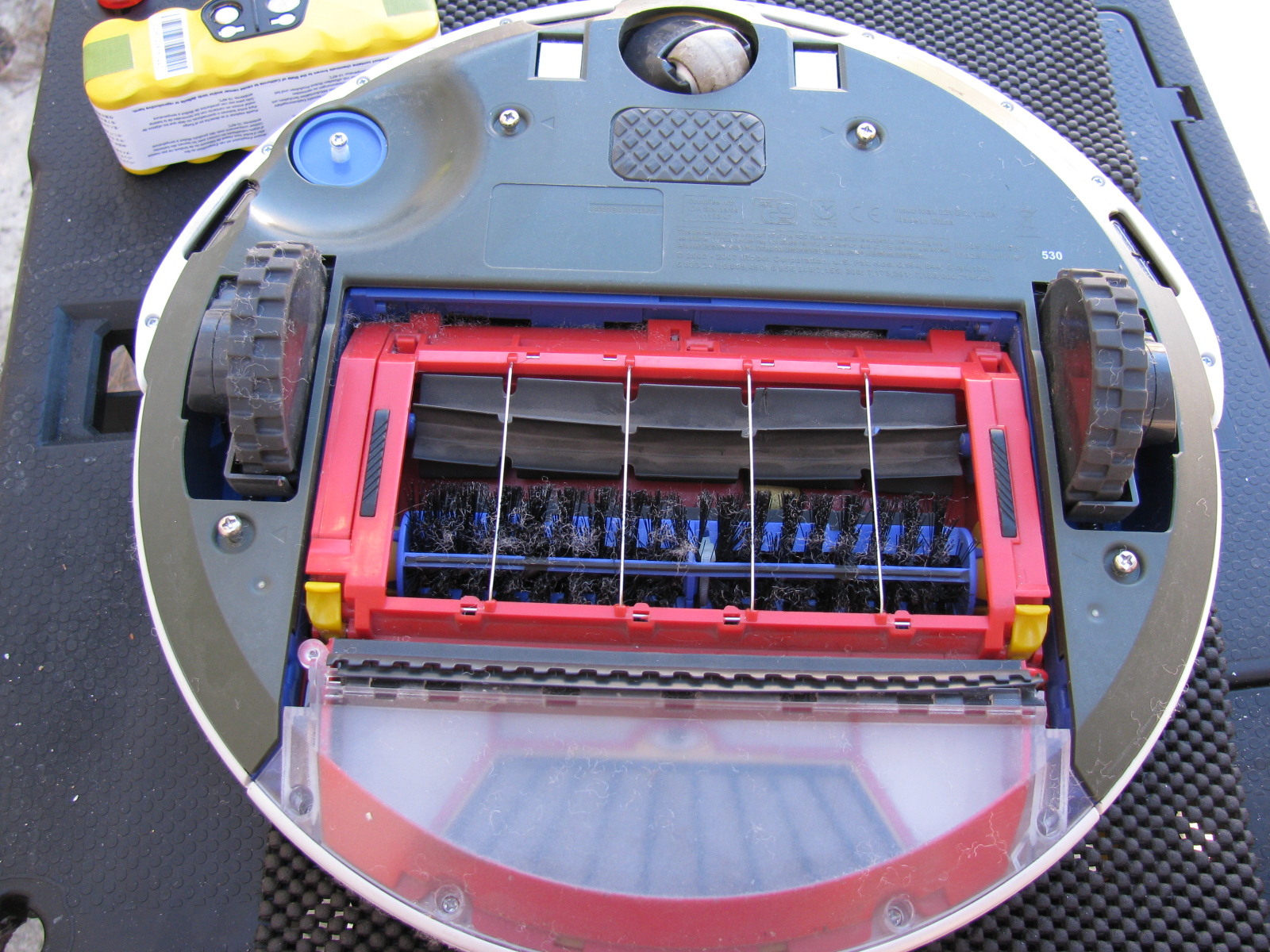
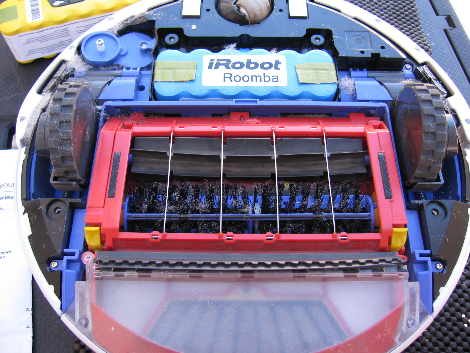
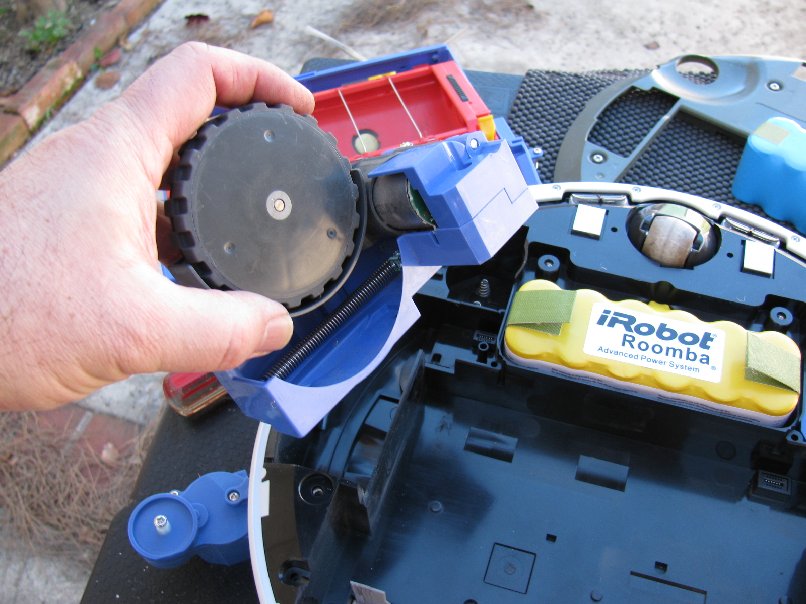
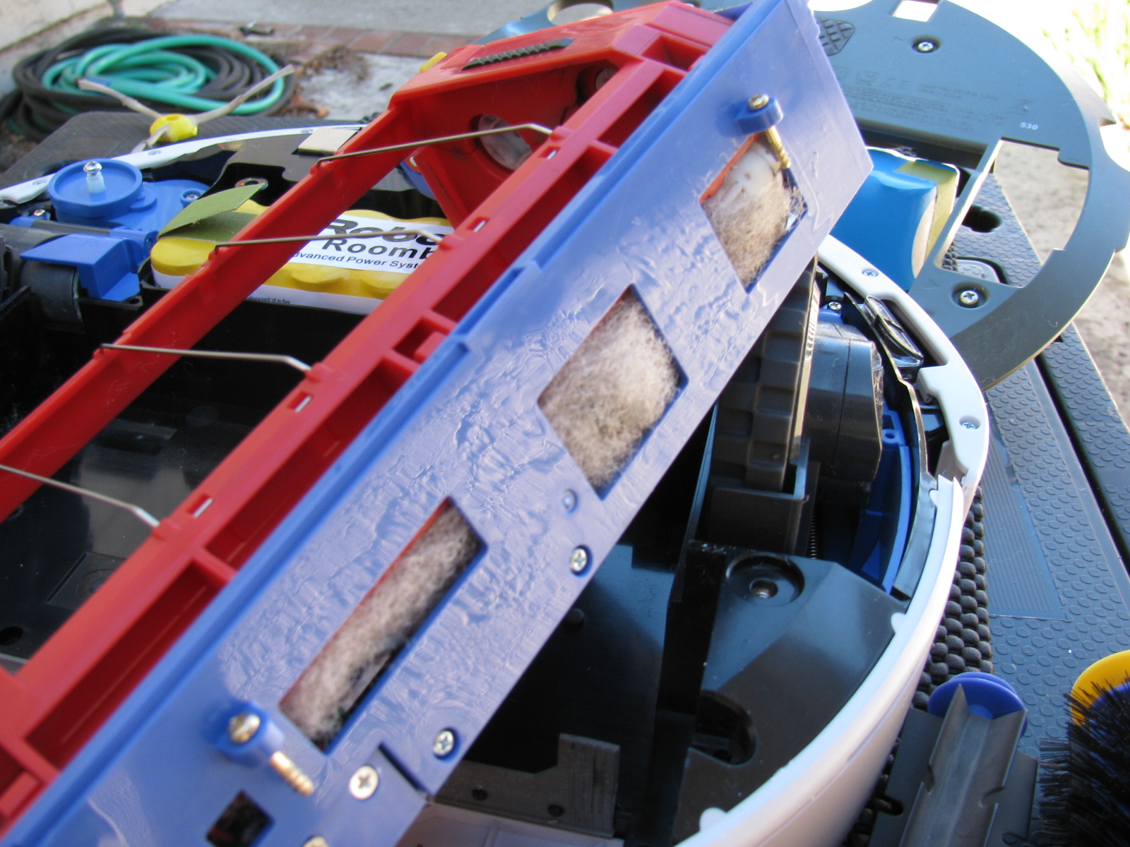
Roomba Battery-Ectomy – Vacuum Cleaner Battery Replacement
After almost three or four years, the battery pack in my Roomba 530 stopped taking a full charge. I re-newed the charge cycle several times, but the Roomba would run out of charge before completing a single room. So I performed a battery-ectomy on the Roomba. It needed a good cleaning inside the chassis anyway, so this was something I needed to do. You can see the debris inside the mechanisms that are impossible to clean unless you open the case. I used my shop vac to suck out the junk inside the various nooks and crannies inside the Roomba. The new battery has a larger capacity and should provide a longer running time. This will be good, since Roomba will help increase my time in the garage and other non-house cleaning activities. . . .
Here are some pictures. . .


It’s been cold in the garage lately (50s-60s), but I wanted to get some more work done on the Coupe. My 302 is scheduled to arrive this month, but I have a lot of work to do before I can install the engine and transmission. This is one of those rare times when I can tell a supplier to take their time.
Back to this weekend’s update: What’s cookin’. When I lived in a small townhouse, I used to make a lot of meals in a Crock Pot, and noticed a few things: First, it was very handy to fill the thing up with various meats and vegetables, turn it on, go away for a few hours and dinner would be ready. Second, the smell was always wonderful. And third, it actually made the house a little warmer.
I decided this third effect of Crock Pot cooking deserved a try in my garage – and it worked. In the morning, I filled the Pot with my universal minestrone recipe and added some leftover spare ribs from the freezer. I call it “Spare Rib Minestrone.” The recipe appears at the end of this entry. It is roughly based on a minestrone recipe from Fat Free, Flavor Full: Dr. Gabe Mirkin’s Guide to Losing Weight & Living Longer. And it is pretty tasty. It made the garage a few degrees warmer, too. Here’s a picture. . .

Cooking in the garage – a tasty alternative garage heating method!
Halibrand-Style Wheels Arrived
The Factory Five Racing Halibrand-style wheels are BIG and beautiful. Wheels are 17 x 9 in front and 17 x 10.5 in the rear, and feature a spin-off hub. I am still not completely sure what tires will go on these rims, my preliminary choice is a set of Goodrich Sport-Comp 2 or something like that. This may change as I get a little farther along on my build.


The Steering Rack
I decided to see if I could finish the front end this weekend, especially since a lot of the back-ordered items arrived – I finally have a complete set of parts for my complete kit!
The steering rack is a non-powered unit made for the Mustang. Like many others, the mounting ears were too close together and I had to spread them out by a little over a quarter of an inch. I tried to use my pipe wrench trick, but the tabs are a little small and I wasn’t able to exert enough torque to move them. Doing some research on the Factory Five forums, I kept reading about people using a nut and bolt to spread mounting tabs wider. I finally found a post that included a picture of this, for future reference, it is located here, and I am posting photos and captions on my site as well so it may be easier to find. It’s a pretty neat trick, although no one says anything about the mounting tabs springing or bending back into their original position – you have to “over-bend” the tabs in order to make the part fit.
Here is my version of the mounting tab spreader tool using threaded rod, washers and nuts – I used 1/2-inch all-thread, since the 3/8-inch rod seemed a bit flimsy:

This really didn’t work too well, the tool needs another nut to hold it securely.

Like this

In the photo above, the open end wrench is being used to spread the mounting tabs outward. If the mounting tabs need to be smaller/tighter, move the washer and nut to the outside of the tab, and tighten the nut – squeezing the tabs closer together.
For the steering rack, I ran into another problem – that turned out to be a non-problem. As you can see here, after spreading the tabs out, the rack fits between the ears – but the holes on the passenger-side need to be moved about an eighth or a quarter of an inch to the left. After thinking about how long this will take using a rattail file, I took a break and thought about the steering rack. The driver’s side mounting tabs had a slot on one side – how come I am not able to move the rack over towards the driver side of the chassis?
The answer is, of course, yes, the slot is just enough to make the rack fit nicely. I used a punch and a mallet to move the rack into position. Success!

Compare the hole on the left (I used silver marker to show where to enlarge the hole) and the slot on the right. No reaming needed – I used a punch and a mallet to move the steering rack into place.
So now the tie rod ends have to be connected to the steering arms. But here is another problem – the driver side tie rod is too long – can I just get a hacksaw and cut off about an inch, as shown by the blue tape?

The driver side steering rack tie rod seems too long – but wait – something is amiss. ..
I decided to stop the steering rack installation at this point and get some answers before cutting the tie rod – because, as Norm Abram always said, “Measure twice, cut once.”
I came across the Summit Racing – Factory Five Racing Roadster build today – and there is a nice picture of the steering rack-tie rod connection posted here – this is for a Roadster, but I think the Coupe shares the same configuration. I have to give F5R a call to verify something – in the Roadster build, the steering tie rod to steering arms are upside down compared to my “dry fit” – Do the Coupe tie rods mount the same way? Also, the Summit Racing car has two lock nuts for each tie rod – my kit came with one lock nut for each side. The manual does not show the ends of the steering rack – poor photo-cropping.
Getting the Shaft
I did some test-fitting of the steering shaft – after some head-scratching moments, I figured out that I needed to remove the adapter that came with the lower end of the steering shaft, and replace it with another one, from another box of stuff. The length is just right, I have seen some early posts about the steering shaft being too long.
But I ran into another problem – the shaft does not come through the dashboard in the correct position. It is not as bad as some others I have seen, but still is quite a ways off. I am not sure if I can just cut the dashboard hole bigger to allow the shaft to come through, and patch the spaces or – what. More fiddling is needed.
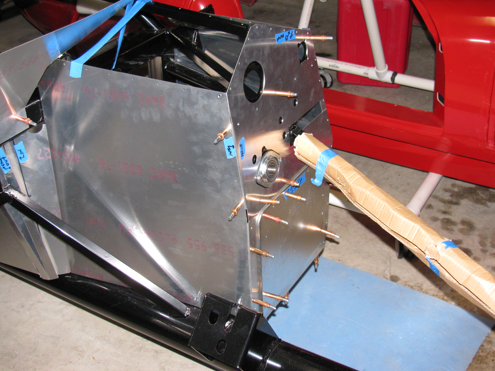
Floor and Footbox Fitting – Passenger Side
I decided to do some more sheet aluminum work – this time, fitting the passenger side floor and footbox. Using the same technique as the trunk floor, I cut the passenger floor into three pieces. After the cutting, I noticed that I could have done this with only one cut, but the three pieces will be OK. I kept the left side un-cut, since it may be seen when the car is done. (I am not sure if I will apply paint or put carpet on the transmission tunnel area yet.)
At this point, everything is being held in place with Cleco pins. I want to test-fit, trim, drill and de-burr all the aluminum panels first, then apply paint – or powder coat them.
So although I think I did a lot of work on the Coupe this weekend, a lot of it does not seem to show. It still does not look like a car yet.

Cutting the passenger side floor.

Passenger side footbox – another jigsaw puzzle!
Something is Making Me Go – “Hmmmmmmm”
I noticed and wonder why the passenger-side side body mount area sheet aluminum is different from the driver-side side body mount area aluminum – take a look:

Driver side – side body mount near the footbox. . .

Passenger side – side body mount area, near the footbox – see the difference?
Here’s another look:

Driver’s side

Passenger’s side. . .
This is making me go, Hmmm. Or more like Arrrrrg.
Season’s Greetings
Somewhere during the weekend, I installed my Christmas lights. I decided to cut back this year, because of all the work I am doing on the car. My “Ho Controller” and box of new lights and other parts I bought last year will have to wait until next year. In the meantime, here is a shot of my display. One of my Universal Rules for events is: “Everything you setup must be taken down and put away.” So many people spend hours and days – or even longer – putting up such decorations. My setup: less than 10 minutes to deploy, and even faster to take down!

Before I forget – here is the Spare Rib Minestrone recipe:
Spare Rib Minestrone
Yield: 6 servings
1 Large onion, chopped
5 cloves garlic, smashed
2 celery stalks, diced
2 cups of chicken stock
1 28 oz can of crushed tomatoes
1 tsp oregano
1 tsp basil
1 can pinto beans
1tsp red pepper flakes
6 small red potatoes, diced
1 large zucchini squash
Some leftover spare ribs, with BBQ sauce
Put everything into the Crock Pot, with the leftover ribs on top, surrounded by the vegetables. Put the Pot on High for about 6 hours or until the vegetables are tender. Based on the Primo Minestrone recipe by Dr. Gabe Mirkin, MD in Fat Free, Flavor Full