Archive for the ‘amateur radio’ Tag
Some friends at the office launched a helium balloon last weekend (Sunday 25 August). We talked about tracking the balloon and of course, I have several ham radio “tracker boxes” that interface a GPS unit to ham radio and then the Internet. Making something small and lightweight could be something that can be part of the payload for a high altitude balloon.
Interestingly, I had a project in my mind ever since I started my various beacon projects many years ago: It is a 21st century message in a bottle – build a disposable, waterproof, floating APRS beacon that I can throw overboard and into the ocean. Then the world can track this thing as it floats around. It will have some instructions on what to do with it if it is found. And, if the finder is or knows a ham radio operator, I will ask that they throw it back into the ocean so it can be found and tracked again.
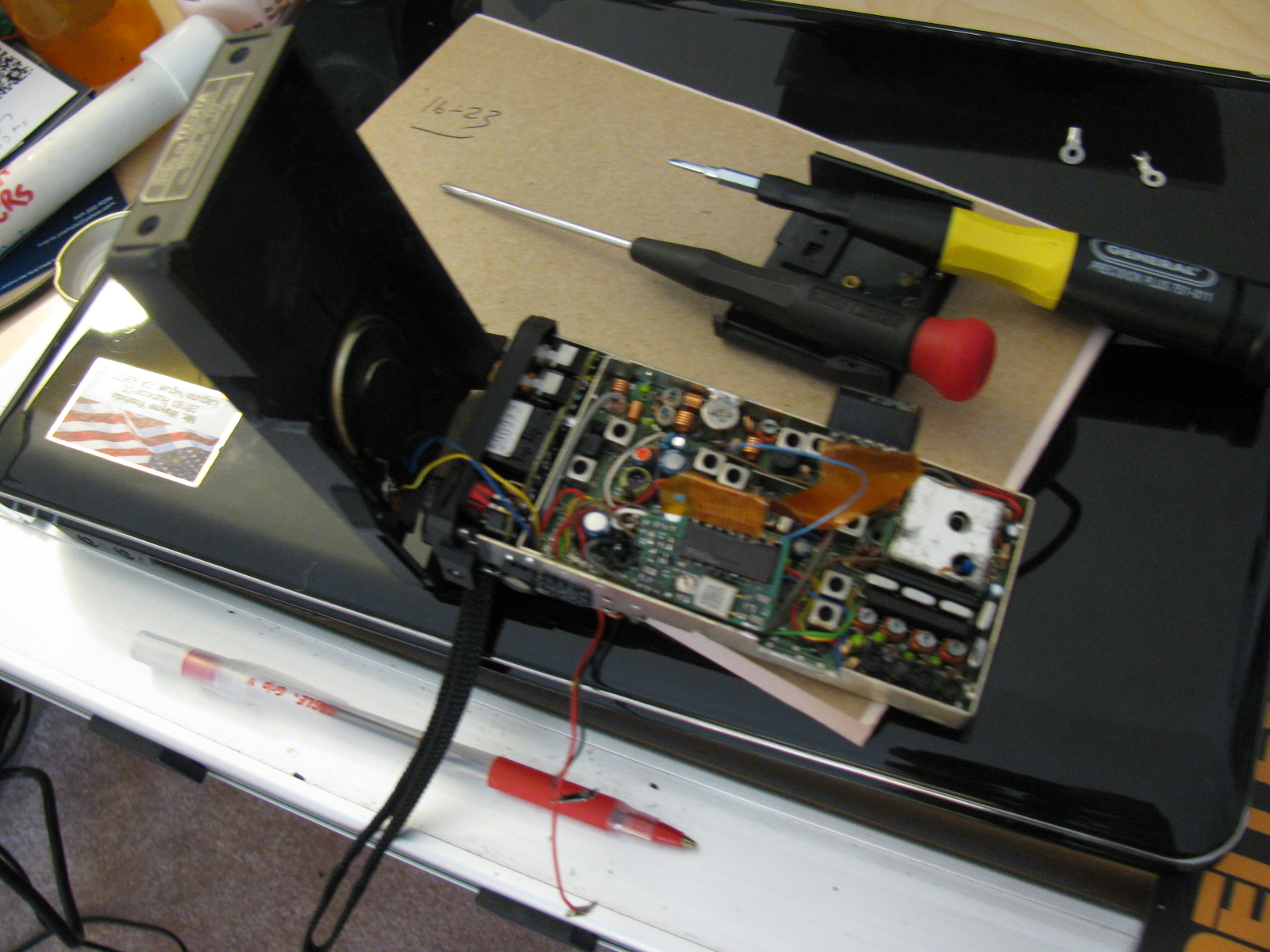
Here is a picture of one of the main ingredients I will be using:

An old but working 2 meter HT can be put to good use as the RF portion of an APRS beacon.
The plastic case, battery pack and rubber duckie antenna will be discarded to reduce weight. LED indicator lights will be disconnected to reduce current consumption. Other parts or functions will be deleted to conserve space, weight and power consumption.
The APRS modem will be a TinyTrak unit, as with my other APRS projects.
I may build two of these, one for balloon flights and one for message in a bottle use.
Discovery Science Center – Advanced Ham Radio on Display at the Meet the Makers Event

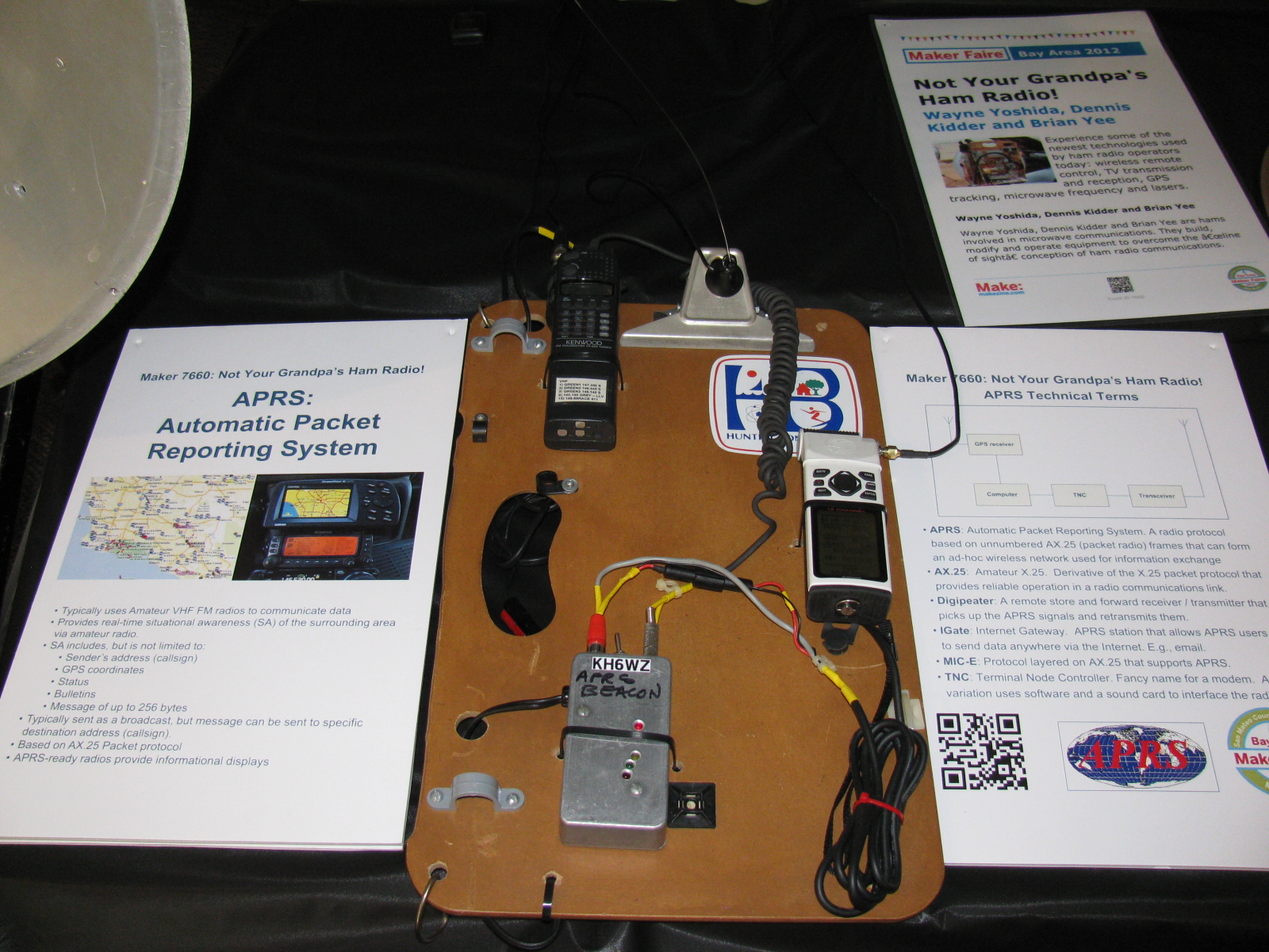
Signage at The Discovery Cube announces the Meet the Makers Event
Dennis Kidder (W6DQ), Walter Clark and I demonstrated our Maker Faire ham radio projects at the Discovery Cube in Santa Ana on June 29 and 30, 2013. We used my TinyTrak APRS beacon to indicate our location during the event. In case the plot is removed or expires, here is an image of the map showing our location. KH6WZ is indicated by the eye icon near the Interstate 5 freeway in Santa Ana.

This is a screen capture showing the KH6WZ APRS beacon data from the Discovery Science Center – Meet the Makers event.
This was a great opportunity to expose people to today’s technology Amateur Radio, and continued along my Maker Faire theme, “Not Your Grandpa’s Ham Radio.”
Dennis brought his dual band 10 GHz and 24 GHz transverter, controlled and interfaced to his software-defined radio (SDR).
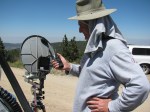
Walt brought his polarization demonstration units, which helped people visualize how radio signals propagate and change as they travel through the air. Here’s how Walt explains his demos:
Two demonstrations show the structure of radio waves – in this case microwaves.
One
The structure of a radio wave in angle around the direction of travel: This is called polarization. A spinning bargraph that has a receiving antenna that also spins will reveal the way radio waves “look” to a receiving antenna. The lesson here is that the receiving and transmitting antennas have to be oriented to the same angle.
Two
The structure of a radio wave along the direction of travel: When a receiver is arranged to look exactly in [or along] the direction the radio waves are going out, reflections can be measured; just like in radar. The reflection off of the hand or the chest of a person causes the speaker to be loud or quiet depending on the exact position. It cycles from loud to quiet every 1.5 cm whether inches or many feet away. The lesson here is that with this equipment, you can picture in your mind the wavelength and especially note that the wavelength is the same no matter how far the radio wave travels.
We did not establish any goals for this event, but there were several memorable visitors to our little table display, including teachers, Maker Faire participants, some current and ex-ham radio operators, many engineers and retired engineers as well as engineering students.
This “Meet the Makers” event was a double treat for me, since this was the first time I visited the Science Center, and I had a blast talking about the new technologies being used by today’s ham radio enthusiasts.
Here are some pictures of this event . . .
-

-
An R/C R2D2 makes an appearance at the Meet the Makers event at the Discovery Science Center.
-

-
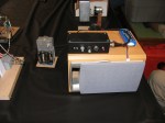
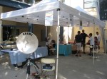
The 24-inch dish antenna makes a great stand for signage.
-

-
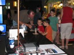
The KH6WZ APRS beacon display at the Meet the Makers event.
-

-
Dennis W6DQ, brought his software defined radio with 10 GHz and 24 GHz transverter to our exhibit.
-

-
Walt brought several fascinating displays to illustrate radio wave propagation.
-
-
Dennis explaining the radio wave demonstration to our target audience: kids.
-

-
Great shot of Walt explaining radio wave propagation to some visitors.
-
-
The Science of Hockey at the Discovery Science Center
-
-
A close-up of one of Walt’s displays
Acknowledgements
Thanks to Bequi Howarth, of the Orange County Mini Maker Faire, who introduced us to the Discovery Science Center.
Links to More Information
Byonics (TinyTrak APRS and Weather Units)
Discovery Science Center, Santa Ana, CA
Orange County Mini Maker Faire, University of California, Irvine (UCI)
Maker Faire
Make: Magazine
American Radio Relay League (ARRL)
CQ Magazine
San Bernardino Microwave Society (SBMS)
Wayne Yoshida LinkedIn Profile

APRS display of the KH6WZ-5 location beacon at the 2013 OC Mini Maker Faire at UCI. Notice the beacon message at the top of the screen capture includes the URL of the event – a great publicity tool!
This past weekend, the second OC Mini Maker Faire happened. And it just so happens to be the second running of my ham radio demonstration called, “Not Your Grandpa’s Ham Radio (2)!” This is my continuing mission to remind people of two things:
First, “The Maker Movement” is nothing new, Amateur Radio operators have been doing this for a almost a century, and nearly 2 million people worldwide are involved in ham radio in some way.
Second, Ham radio is not necessarily an old man’s hobby where weird guys talk to strangers from garages and basements. We are skilled wireless communicators and use today’s technology, from GPS and microprocessors to lasers and microwave frequency linking.
This time I added static and working displays of my various APRS beacons (KH6WZ, KH6WZ-5, and others). I programmed the OC Mini Maker Faire’s URL to the beacon message so people can take a look at what was happening – an excellent publicity tool!
I also planned on making some 10 GHz contacts with my rig, since this was also the same weekend as the ARRL 10 GHz and Up Contest. The transverter covers were removed so people can see the system’s guts.
Based on previous experience at the Discovery Science Center “Meet the Makers” event, I demonstrated radio wave polarization- horizontal vs vertical – with my rig and the microwave strength meter.
Since I had plenty of space, I shared my booth with a company that makes interesting computer and microprocessor related items. This may sound trivial, until you realize this company is run by these three young guys . . .
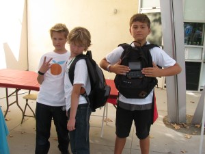
Huxley, Max and Ethan showing one of their products called the SmartPac.
There seemed to be more people at this Faire, probably since not too many other events were happening nearby. The 405/605/22 freeway closure did not affect the MF, since it started after the event ended.
More than a dozen hams – either active or at least licensed – stopped by to visit. We talked about this event as well as the Bay Area Maker Faire, and what ham radio activities we are involved with.
One more thing: I met several guys from the San Diego area – they are finalizing the plans to have a Mini Maker Faire in the San Diego area – this is great news. Stay tuned and I will announce an update as soon as I hear something from the committee!
Here are some pictures from the event. I am already thinking of building some new displays for next year.
-
-
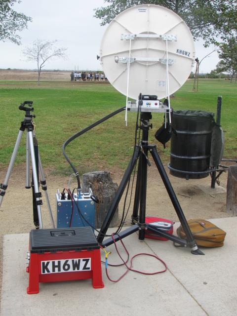
The 24-inch M/A-COM dish with the KH6WZ logo makes a pretty decent sign for the booth, eh?
-

-
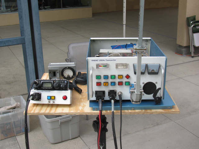
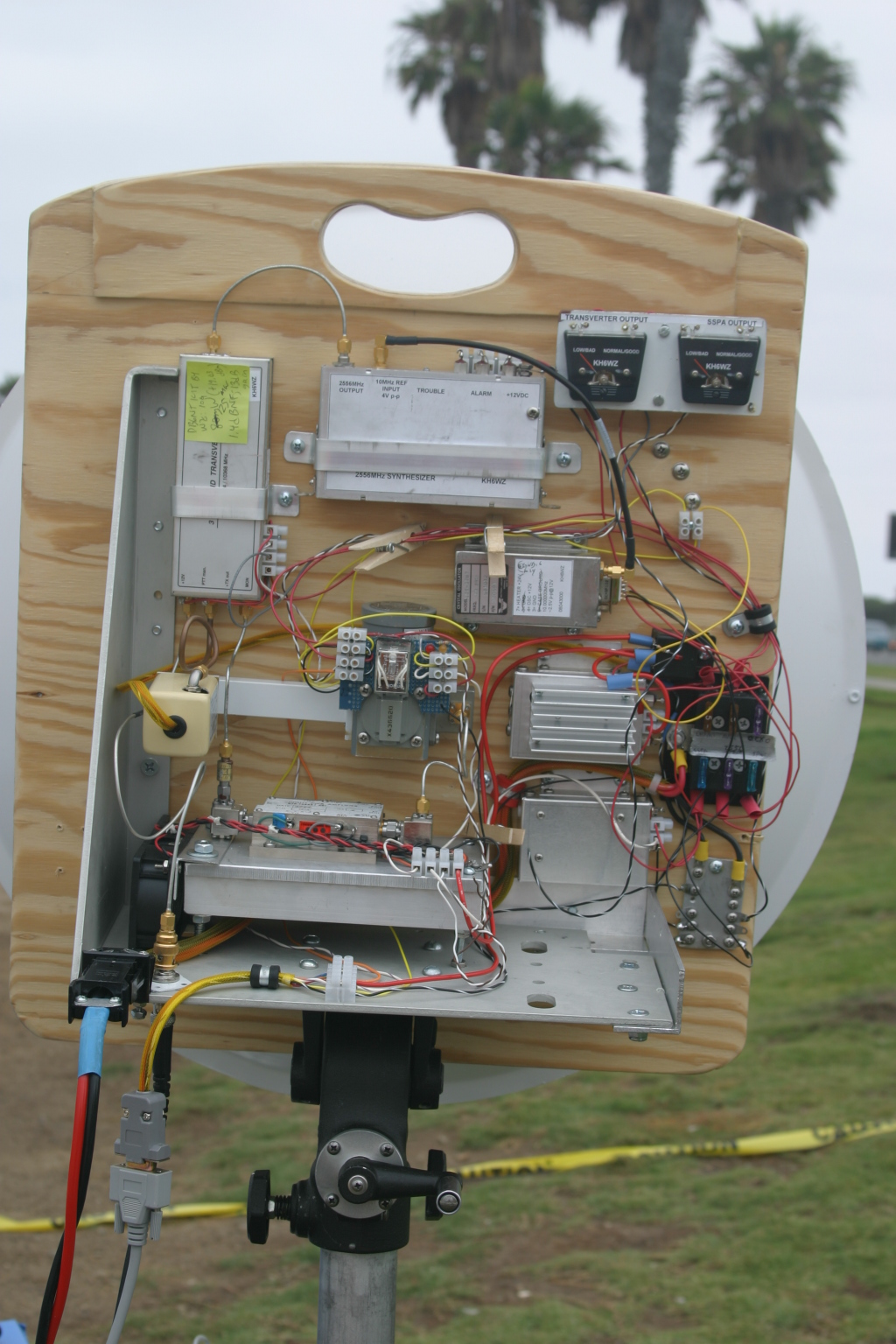
The KH6WZ 10 GHz transmitter-receiver unit on display at the Orange County Mini Maker Faire on the UCI campus
-

-
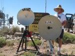
KH6WZ horn antenna and microwave field strength meter at the OC Mini Maker Faire 2013
-

-
The KH6WZ APRS beacon (unit 1) at the OC Mini Maker Faire 2013. This was a static display unit to show components and construction.
-
-
KH6WZ-5 APRS beacon – active and sending position data at the 2013 OC Mini Maker Faire at UCI. The beacon message included the Faire’s URL.
-

-
This familiar unit makes an appearance at the Maker Faire. . .
-

-
The robot “Titan” was a crowd pleaser – it throws flying discs and comes to you for a refill.
-

-
Track Roamer robot at the OC Mini Maker Faire. Notice the Nerf gun. When you come to next year’s event, remember to wear a red shirt.
-
-
One of the “roving displays” at the OC Mini Maker Faire 2013.
-
-
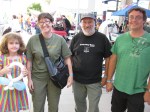
Some ham visitors at the Orange County Mini Maker Faire 2013: Haliey, Michelle W5NYV, Paul KB5MU and John KJ6HZ.
-

-
Michelle W5NYV wearing her daughter’s alpha wave ears. The ears move and react to pulses from a sensor clipped to her left ear.
-

-
An unknown couple wearing Vocademy shirts. What a great slogan: Eat, Sleep, Make.

Microwave radio dishes used for ham (Amateur) radio communication.
The Orange County Mini Maker Faire is coming up (August 17 at UCI), so I added this intro to ham radio on the microwave bands. The Maker Fair coincides with the ARRL 10 GHz and Up Contest, and so, rather than missing the contest, I thought it would be fun to try working the contest from the Maker Faire. . . . .
Click here to view the presentation>>>> Microwaves: Not Just for Leftovers

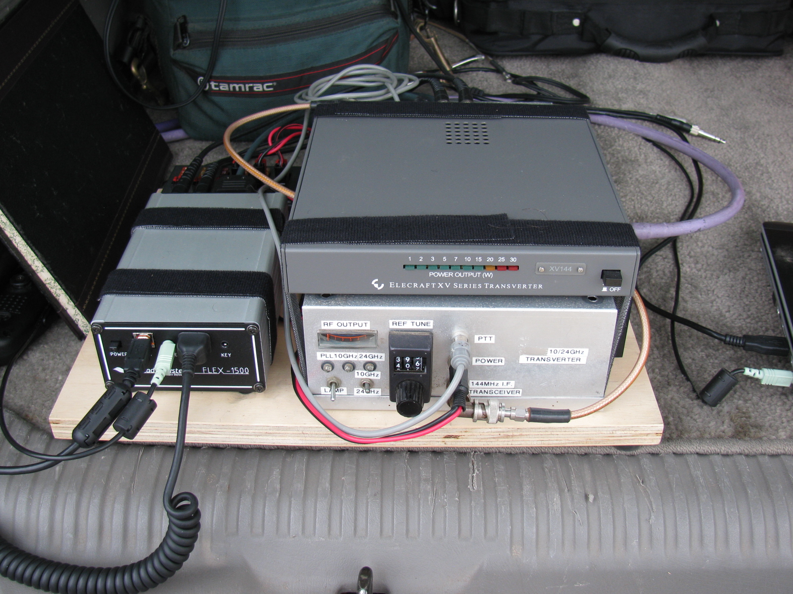
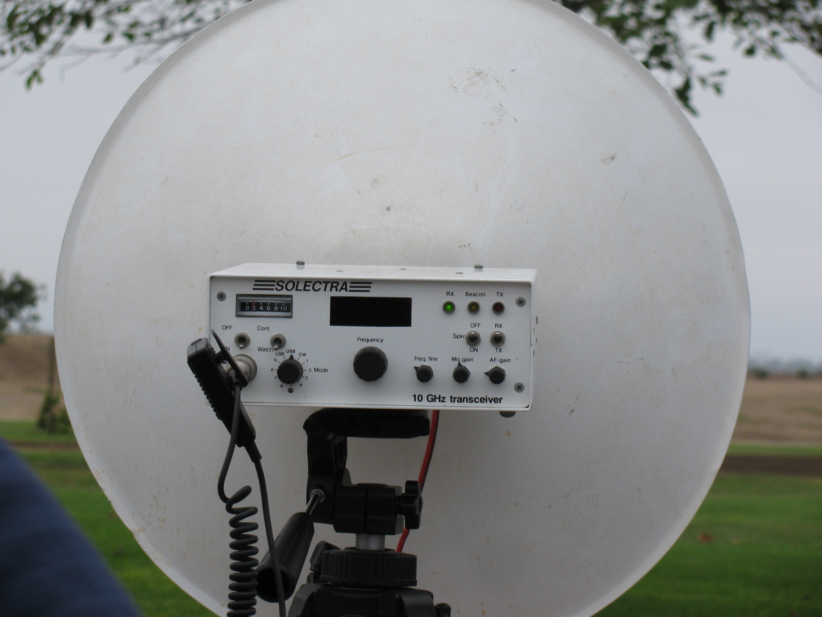
KH6WZ 10 GHz rig at a tune-up party
A presentation about record-breaking two-way ham radio contacts during the 2007 10 GHz and Up Contest
View the slide show in PDF >>>> XE2 to W6 in the 2007 10GHz and Up
Microwave Contest Driving Directions from the Glenn Allen KE6HPZ List (Originally from SBMS Newsletter, January 2004)
Note:
This is a copy and paste (with some minor edits) from a post by SBMS member Glenn, KE6HPZ and some additional postings from other members. I have operated from many, but not all of these locations, so verification with new maps or other means might be a good idea. If you have a correction or would like to add a “known good” contest location, please let me know and this list can be updated.
Some pictures will be posted as I find or make them. . . .
Click the link below for a PDF version of this list:
Microwave Contest Driving Directions from the Glenn Allen KE6HPZ List
**Update** Thanks to Dan, K6NKC, here is a link to the KE6HPZ list on the SBMS website.
Goleta State Beach – DM04bk — This location has a good shot to the Baja gang. It is DM04bk, and we parked right in the parking lot of the Goleta State Beach. In the Santa Barbara area, take the 217 Highway south from the 101 Highway, about 1.9 miles. Get off the freeway where it says Goleta State Beach, and cross over a bridge and you will be entering into the beach parking lot. Turn right, and go about a ?? of mile down the parking lot till you find a place that has no trees in the way, and shoot over the water. (N34 25′ 0.6″ W119 49′ 58.2″)
Summerland (Santa Barbara) Lookout Park – DM04ek – To get to this location, get off at Evans Street in Summerland, near Santa Barbara. You can try working from the park which is on the south side of the freeway, but there are trees in the park, and we found that parking lot was full. For those that have to work out of the back of their trucks this place didn’t work. So, we found a better spot, still on the South side of the freeway, just .2 miles east of the park. Get on the southbound on-ramp to the 101 freeway, which runs beside the freeway. Right before the on ramp enters the freeway there is a small road the will break off to the right. This is Finney St, and it goes over the railroad tracks and goes into a parking lot. From the parking lot it goes east down the hill. We just pulled of the side of the road, and worked Baja. This spot is DM04ek (N34 25′ 09.1″ W119 35′ 46.1″) I used an 11 element 440 beam to get into Signal peak, or one of the San Diego machines.
Ventura (Grant Memorial Park) – DM04ig – To get to this location from North bound 101 get off at California St. There is no South bound off ramp for California St. Get off of the next exit (Harbor blvd, or Seaward Ave) and get back on the North 101 freeway and get off at California. Head up California (N) till you hit Poli Street (California Tee’s into Poli). Turn Left onto Poli, and turn right on the next street, which should be very small street. (Brakey St). It winds through some houses, and climbs up the hill. You will come to a four-way intersection, of small roads on the hill. Take the left or lower road a couple of hundred feet down the road, to a turn out. The location is DM04ig (N34 17′ 05.3″ W119 17′ 41.3″) at 300 ft above Sea Level.
Point Mugu – DM04lc – The operating position of Point Mugu is right next to the very huge rock. On the east side of the Rock there is a parking lot. It is on the south side of the road. So you cannot turn into the parking lot going north bound on the 1. Only the southbound traffic can turn in to the parking area. So if you are going North on the 1, continue past the rock, and turn into the parking lot on the North-west side of the rock, and come out of the parking lot and head south on highway 1 to go around the rock, and go to the other parking lot. The location is DM04lc (N34 05′ 13″ W119 03′ 43″) I have found that this location is blocked to DL29cx, and DM10xl by Catalina Island.
Point Dume – DM04na -Point Dume itself has a bunch of No Parking Tow away signs. So I set up on the South side of the road a couple of miles North-West of Point Dume. There is a large dirt pull off that worked great. Its location is DM04na (N34 02′ 09.8″ W118 51′ 27.4″) I was also able to work people on PV across the tip of Point Dume. Catalina Island gets a little bit in the way when the Baja guys are in DL27.
Las Floras Canyon – Somewhere near Las Floras Canyon Road at Highway 1. Stay in the Floras area. If you go too close to Malibu, you will be below 10 miles to the Point Dume location. If you go too close to Topanga Canyon you will be shooting through PV.
Palos Verdes North and South – DM04ts – The easiest way to get to Palos Verdes is to come in from the 110 Freeway. Get off at PCH (Pacific coast Highway) Highway 1(N33 47′ 26.1 W118 16′ 55.0). Go West 3 miles on PCH, and turn left on to Crenshaw (N33 47′ 31.6″ W118 20′ 00.6″). Go 3.4 mile on Crenshaw up the hill. Turn right on to Crest (N33 46′ 07.4″ W118 21′ 50.1″). Go 1.6 miles on Crest. Go through Hawthorne Blvd, 150 feet. Pull off to the side of the road, and this spot works Frazier and other north locations. Its location is DM04ts (N33 45′ 41.2″ W118 23′ 39.8), and it is 874 ft above Sea level.
PV South – DM04tr – Turn around from the North location, and turn right (South) and go 1 mile down Hawthorn Blvd. The location in on the south side of a divided road, so pass up the location, and make an U-turn at the Salvation Army driveway. Head up the hill to the vista point. There is parking for about 4 cars here. This spot points south to San Diego, and Baja very well. This location is DM04tr (N33 44′ 53.3″ W118 23′ 39.4″). It is 535 FT above Sea Level.
Huntington Beach I – DM03xq – Huntington Beach works well to Baja. During the middle of the day it might be hard to find a parking spot. Pacific Coast Highway (Highway 1) runs along the beach for miles. So if you can get into one of the parking spots, just point out to Baja. Metered parking DM03xq. The Huntington Pier is DM03xp (N33 39′ 17″ W118 00′ 16.2″). Take Beach Blvd south off of the 405 about 5.8 miles to get to PCH.
Huntington Beach II – DM03xq – An alternate DM03xq to number one above is the park that overlooks the Bolsa Chica wetlands. This place is called Overlook Park. This location is accessed via Seapoint, off PCH. Take Seapoint to the east, and at the intersection of Garfield Ave, continue thru the pipe gate, up the hill. Continue to the farthest parking spaces, near the handicap parking slots. There is plenty of parking, and not much visitor QRM, but no restrooms or water fountains. This location gets very windy in the late afternoons. This location is not good to the south to San Diego or to Mexico via a direct path. Marginal signals may be possible via a reflection/refraction off Catalina Island or the oil derricks offshore to the west and over the water. Note – please respect the privacy of the residents there. Complaints may lead to closure of the park to the public. (KH6WZ)
Signal Hill North and South – DM03wt – To get to Signal Hill you have to exit the 405 Freeway at South Cherry exit. Head south on Cherry Ave .8 miles and turn left onto Skyline drive, and head up the hill. When you get to the top of the hill, and you can turn left into the park at the top. You can work east (Heaps) and North (Frazier) and west up the coast to Ventura and beyond. To work San Diego and Baja, you pass by the park and continue to Southward about .3 miles on Skyline, to a dirt field on the right, (N33 47′ 54.7″ W118 09′ 34.1″) DM03wt
Fairview Park, Costa Mesa – DM13ap – this is where the SBMS Tune-Up Picnic is held. Address is 2501 Placentia Ave. It is near the intersection of Placentia and Adams. Across the street is Goat Hill Junction, a miniature train station. The gravel parking lot may be used if parking at the part is not available. – NOTE this is only 9km away from Huntington Beach (DM03xq) – too close for the ARRL contest, minimum 16km/10 miles.
El Segundo (North side of Hill Top Park) DM03tw – To get to this park, get off of El Segundo Blvd, and head west about 1.4 miles. Turn right on Sepulveda Blvd (Highway 1). Go 0.2 miles and turn left on Grand Ave. Go 0.6 miles to Maryland St, and turn right. Hill Top Park is on the left and go down the street 700 ft to the public parking structure on the left. Go up on the parking structure – there is no roof, so overhead clearance is no problem, except for low-hanging pine tree branches. Go to the parking locations that are marked on the map, and point between the trees. This is the highest point that you can get to in El Segundo at a high altitude of 176 ft, plus the height of the structure. The only thing in the way from this location is piece of PV that is 250 ft high. The location of the structure is N33 55′ 14.7″ W118 24′ 25.1″
Highway 2 Overview (La Canada) – DM04vf – From the 210 Freeway you will exit Highway 2 Angeles Crest Highway. This is National forest area. This area requires daytime headlights, and you will get a ticket for not having them on. Be aware that the rangers will write you up for having a battery out in the open, because of fire danger. So leave the battery in the vehicle, and use something else heavy to keep the tripod from blowing over. To get there, head North up the hill 2.5 miles and you will see a large dirt pull-off on the right. It has an elevation of 2000 ft, and it talks south. But lower Baja locations were weak to this location. You have a large mountain right behind you so you would have to do a bounce shot to get anywhere else. DM04vf (N34 13′ 41.3″ W118 11′ 09.6″)
De Soto and 118 Freeway – DM04qg – It is located just north of the 118 Freeway and get off at De Soto Ave. It has talked to both the closer and farther away Baja locations. Just find a high spot above the freeway DM04qg (N34 16′ 32″ W118 35′ 17″) around 1300 ft elevation.
Secret Site 51 (Loop Canyon) – DM04ti – Secret site 51 is a great spot for talking all over the LA Basin and much south. It is located at (N34 21′ 13.4″ W118 24′ 58.4″) DM04ti at an elevation of 3918 feet. It takes about 30-40 minutes to get up there, from the 5 and 14 highway spilt. To get to there, get on the 14 freeway (3.3 miles) and get off at Placerita canyon road. Turn right, and go south-east (5.1 miles) on this road till you hit Sand Canyon Road (N34 22′ 51.8″ W118 24′ 48.4″). Turn right on Sand Canyon road for 2.9 miles up to Bear Divide (N34 21′ 35.1″ W118 23′ 33.1″). Turn right, and go up the road (3N17) (2.9 miles). You will come first to Contractors Point (repeater site). Continue down the road 1 mile to Fire Camp 9. Drive slowly through the camp, and go 0.4 of a mile up the hill, to the repeater site. Park on the side of the road about 100 ft down from the gate at the repeater site. This will give you a clear shot at Mexico, and a clear shot at Frazier. If you have a portable rig, you can walk up to the top of the hill and have a 360-degree view.
-
-
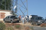
Everyone lines up at the base of the tower and near an LNG tank.
-

-
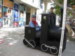
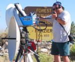
Even a broken rig can be used on Secret Site 51!
Whitaker Peak – Whitaker peak is close to the 5 freeway, and it takes about 10 to 15 minutes to get up there off the freeway. It has a good shot South. It does not have a shot north. You can do a bounce shot to Frazier off one of the hills to the east. It is located at (34′ 56.2″ 118 deg 43′ 08.8″) at 3646 ft. It is between Castaic Lake and Pyramid Lake. To get there going north on the 5 freeway, get off at Templin Highway (N34 34′ 20.8″ W118 41′ 27.6″). Go under the freeway and head north about 2.4 miles on the old road, running beside the freeway. On the left you will see a small one-lane road. It is labeled 6N53 (N34 35′ 05.6″ W118 42′ 56.7″). If you are going south on Highway 5 you can get to the old road, by get off at the Brake Inspection area. Just at the end of the area, were the road is about to get back on the freeway, there is a little road that will turn off to the right (N34 35′ 03.2″ W118 42′ 36.8″) that will take you to the old road, in a few feet. Turn right and you will be at the 6N53 in a ?? of the mile. A few feet up the 6N53 there is a fork in the road. Take the left fork and start heading up the single lane that is a somewhat asphalt road. This road is about 1.8 miles long. You will have a microwave repeater site in front of you, and a gate in front of you. Look behind you on the ridge and you will see a small dirt road running the ridge. Run up the ridge, about a ?? of a mile to a high spot. This is room for about 2 trucks. You will have to do a couple point turn, to turn around, to come back down the hill.
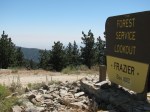
Frazier Peak- DM04ms – (N34 46′ 28.4″ W118 58′ 7.3″) Frazier Peak is 8400 ft mountain that has good shots all directions. There are some trees to the South. It takes 45 minutes to get up there from Highway 5. From Highway 5, get of the Frazier Park exit. Head west on Frazier Mountain Road 6.9 miles. Turn left on Lockwood valley road. Go 0.9 mile down the road. Turn left to into the Ranger Station (8N04) Go through the ranger station, and head up the road about a mile up the road you will go past a campground. Continue up the road about 6 miles to the top of the hill. There will be several forks in the road. There should be a sign that points toward the fire lookout.
-
-
KH6WZ on Frazier Mountain – a great microwave contest location
-
-
John KJ6HZ with his 10GHz transverter system. KH6WZ system on the left
-
-

-
-
Frank WB6CWN and his portable 10 GHz rig at Frazier
-

-
KH6WZ, KJ6HZ and others at Frazier August 2009
Comments and Updates from the SBMS Reflector (old)
PALOS VERDES updates, August 2009
One of the best locations for working north is from the rear parking lot of the Rancho Palos Verdes City Hall.
From: Glenn Allen
A few hundred feet away is a Giant Repeater site, on the back of a church school.
33°46’10.42″N
118°22’34.93″W
I have operated for a short time for a UHF/VHF contest from the back of the church parking lot. But the RF noise floor was high. A parking lot to the north of the repeater site is a rest home, and I pulled into the back of that lot for a quick contact, but it was hard to hear the coordination radio. I was hearing News, weather and sports…
Doug Millar wrote:
This is probably the only turn out on the North side of PV with a good NW SE look. It is 300ft above PCH and sea level and easy to get to: At the corner of Pacific Coast Highway and Anza Blvd. go south. Anza turns into Vista Montana. Go up the hill to Via Corona and turn right. A short block and you should be at a cul de sac that overlooks the area. I doubt if it is 10 miles from San Pedro, but it is plenty from Signal hill: 33d48′ 23.09″ N 118d21′ 59.09″ W.
Mulholland
Alternative to Mulholland: NIKE PARK – DM04rd
Lat and lon for Nike Park (DM04rd): 34 07 42.25N, 118 30 47.00W. You will need to take the 405 freeway to get to it. Take the Skirball Center Dr/Mulholland exit. There are a couple of turns you need to make in order to get on Mulholland. Do not take Sepulveda unless you want to take a scenic route through some neighborhoods.
Also, do not try to use a gps nav aid or Google maps to get you there. It will try to send you a way that you cannot take. Just follow Mulholland Drive.
This place is a park and according to the signs the gates close at 6pm. That is gate on Mulholland that closes at 6pm. The road is a bit rough in spots but even in my Honda Civic it is still drivable. You just need to be careful.
Chris n9rin
From Ed, W6OYJ of the San Diego Microwave Group:
Mount Soledad – DM12ju – in San Diego
I am writing these notes for anybody to use getting to our famous 822 ft mountain. (More real DX has been worked from here than from Pike’s Peak!) Getting to Mount Soledad in San Diego is easier now, but still confusing. Most maps do not show the following changes. The name of Ardath Road has been changed to La Jolla Parkway. The Hidden Valley Rd intersection has been moved.
1A. If you are arriving on I-5 from the South (Downtown San Diego), take the La Jolla Parkway Exit (It used to be named Ardath Road). Follow it over the summit, stay in the left lane. Turn left at the first signal onto Hidden Valley Rd. Go to Step 2.
1B. If you are arriving on I-5 from the North, Stay on I-5 at the I-5/I-805 junction. After passing Gilman Drive, take the Hwy 52 East (Yes East!) Exit and continue about 3/4 mile on Freeway 52. Take the Regents Road Exit, turn left under the Freeway 52 overpass, and turn left again to get on Freeway 52 WEST. Move into the far left lane and continue as it goes up over I-5 and merges with La Jolla Parkway. Stay in the left lane. Turn left at the first signal onto Hidden Valley Rd. Go to Step 2.
1C. If arriving on I-15 from the North, stay right and take Freeway 163 at the I-15/Fwy 163 split. Then after a few miles take Freeway 52 West. Go several miles, stay on 52. After passing the Regents Road Exit move into the far left lane and it will merge with La Jolla Parkway. Stay in the left lane and turn left at the first signal onto Hidden Valley Road. Go to Step 2.
2. Continue ahead on Hidden Valley Rd. Pass the stop sign. Follow the double yellow lines as it curves while gaining altitude. Eventually you yield and turn right at a Tee-intersection onto Via Capri. This steep road climbs through residential areas until it reaches the roadway summit with a sharp right turn at a yield sign. Stop here at this blind corner, signal a left turn, and wait until the traffic from the right is clear. They do not stop! Turn left into Mt Soledad Park. (Gate here supposed to open at 7 A.M.)
3. On your immediate left is a paved parking lot (overflow parking). The north point of this parking lot is a good spot for working stations to the NW, N, and NE. It is blocked by the higher part of the Park toward the ENE, E, and ESE. From this same parking lot, on the side next to the Park entrance road, you can find a spot with a view to the SE, over Downtown San Diego. This location works for direct shots to Baja. The problem with this location is that you cannot work Arizona or some of the SD locals due to the terrain blockage to the East. There are usually very few tourists here.
4. The main part of the Soledad Park is the area just east and NE of the big Cross at the summit. As you proceed up the park road, stay to the right as it goes counterclockwise around the Cross. There are only four parking places in the first parking area East of the Cross. These are closest to where you want to be, but you have to be lucky to get one. Further around the Cross on the North Side are about 20 parking spaces. This is where most of the tourists congregate, but they will find you in either spot. From these two locations you can attempt to work Arizona. The first spot is best overall, though due to recent concrete “improvements” at the Veterans Memorial surrounding the Cross, you will have to move North a bit to allow direct shots toward Gaviota (304 degrees true).
5. True beacon headings from Soledad: Palos Verdes=314, Frazier=324, Santiago=344.5, Mt San Miguel (San Diego)=119. The grid square here is DM12ju.
6. Bulletproof shielding and filtering is a must for Mt Soledad due to megawatts of TV, FM broadcast, paging, and commercial radio comms.
7. If you want to go home on I-5, you will have to retrace your movements back to Regents Road and again do a U-turn under the 52 Freeway, so you can go west and take the “Los Angeles” ramp to I-5 North.
Closing Note
If you are a licensed ham operator already, and want to try a new challenge, visit the San Bernardino Microwave Society (SBMS). Meetings are held the first Thursday of each month in Corona, Calif. and are broadcast on W6ATN/BATC.tv
For more SBMS information, go to http://www.ham-radio.com/sbms/

This past weekend, some of the active San Bernardino Microwave Society (SBMS) gathered at Fairview Park in the early morning to perform a field test of their microwave systems. Since I did not do anything with my rigs this past year, I decided to skip this field test, and take some pictures of any new more interesting rigs for this contest season.
Here are some pictures of the various station equipment SBMS club members built and tested that day . . .
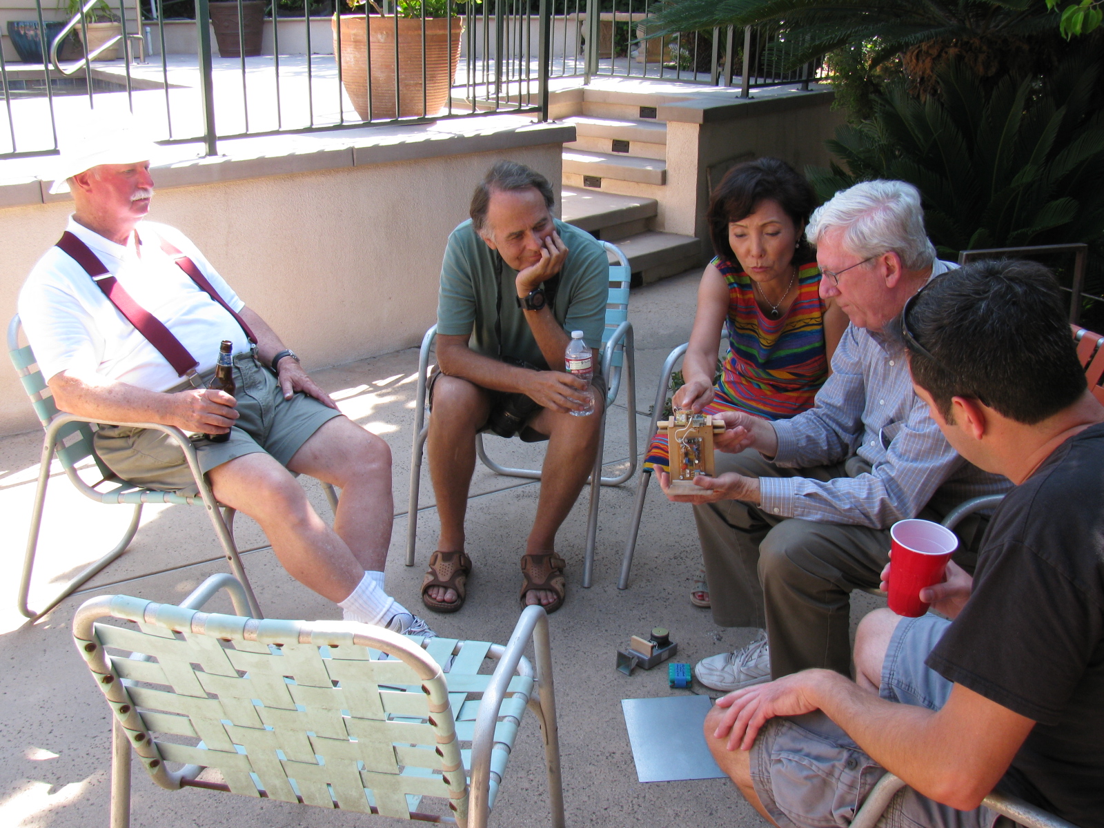
A post-Tune Up Party party and BBQ was held at Dennis W6DQ’s house. It was nice to relax and visit with the other SBMS members and enjoy some great BBQ chicken….. In the picture below, Walt, WALT explains one of his radio wave demonstrations to a captive audience… Watching and learning, from left to right are Bill Preston, KZ3G; Dan Slater, AG6HF and wife Sandy Slater; Walt, and Jason Sogolow, W6IEE.

If you are curious about the test setup, here is an article written by Kerry Banke, N6IZW, with some small edits by me:
Checking Microwave Radio Performance with a Simple ERP/MDS Test Unit
By Kerry Banke, N6IZW (Edited by Wayne Yoshida, KH6WZ)
Before heading for the hills with 10 GHz equipment around contest time, members of the San Diego Microwave Group (SDMG) and the San Bernardino Microwave Society (SBMS) check the Effective Radiated Power (ERP, transmit) and Minimum Discernible Signal (MDS, receive) with the simple setup described in this article. We hold the test sessions at the June and July meetings in preparation for the ARRL 10 GHz and Up Contest in August and September. The advantage to having two sessions is that it provides a second opportunity to verify improvements or allow participation if the first session is missed. The test unit works with both wide band and narrow-band radios.
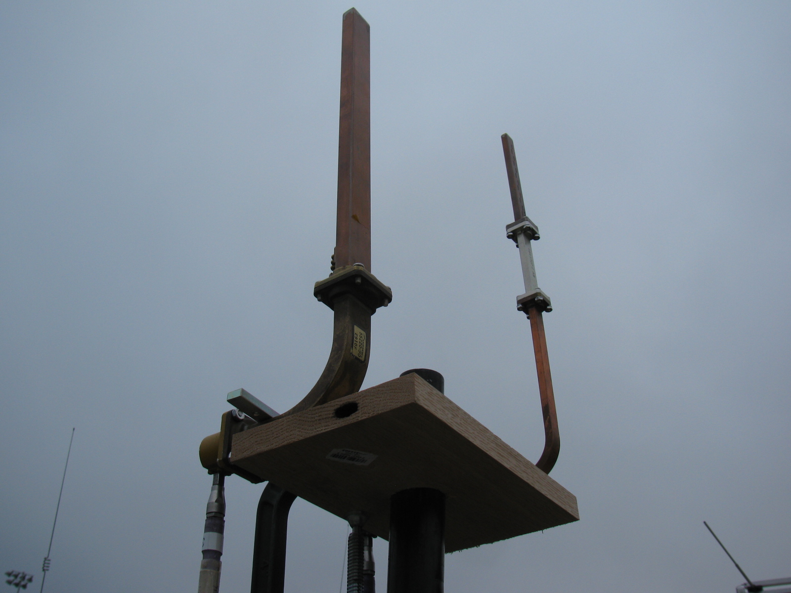
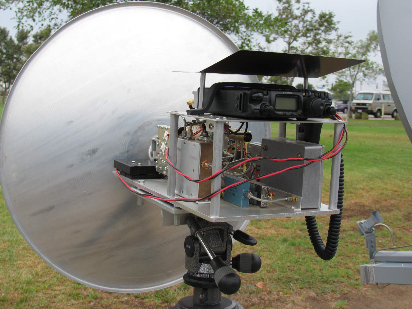
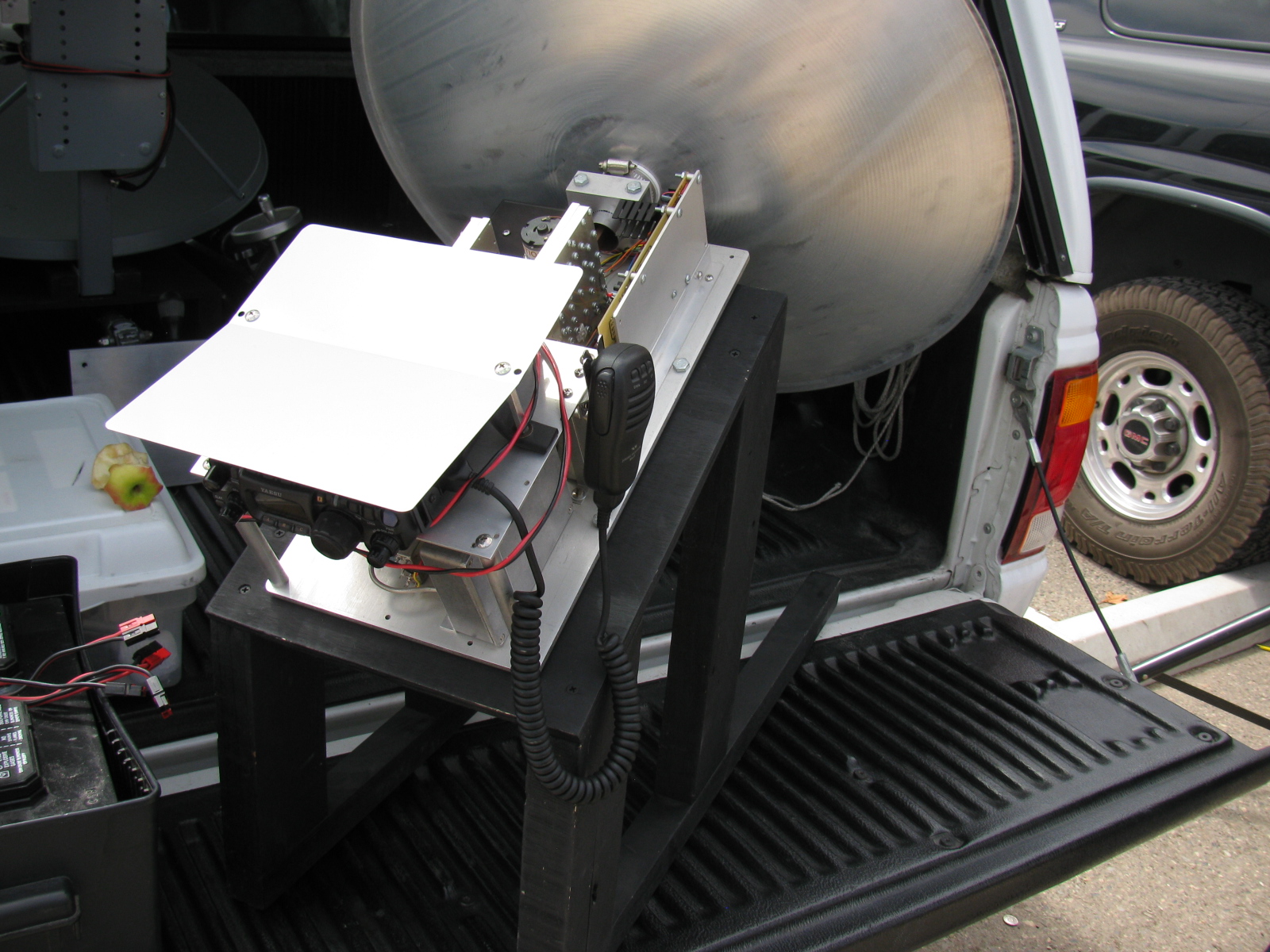
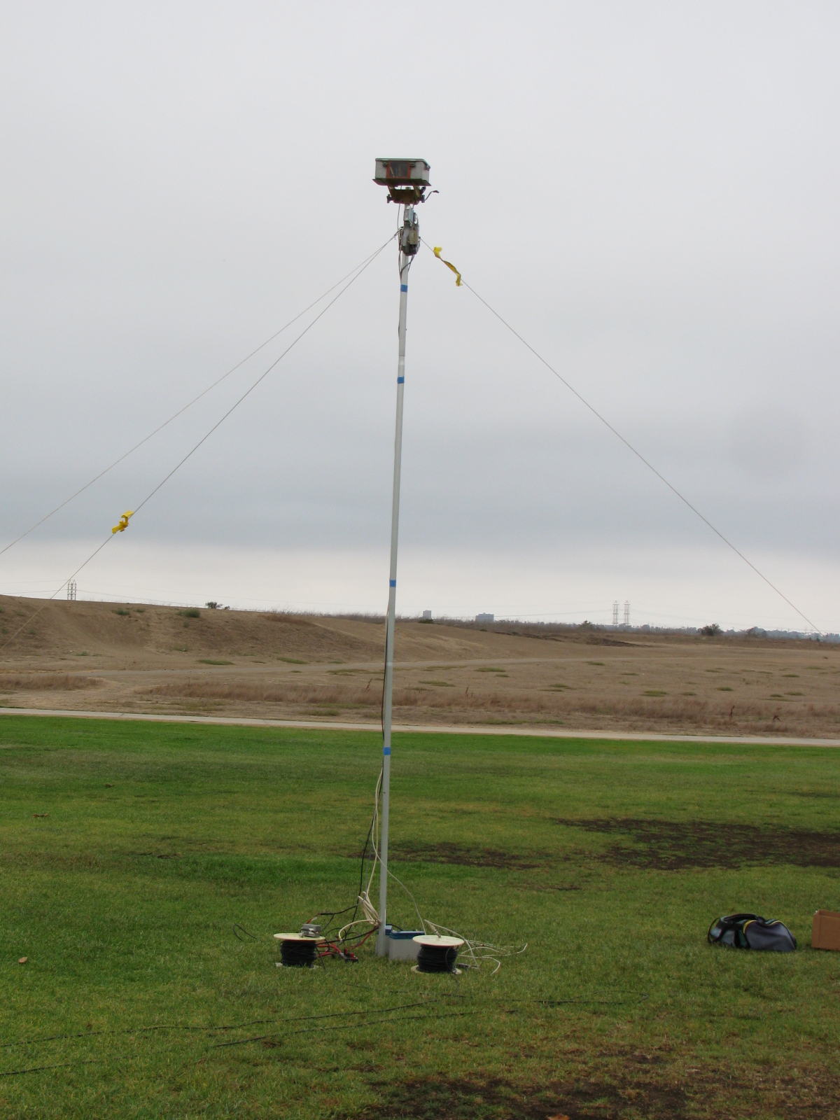
The Pole-Mounted Test Setup
The setup consists of a pole mounted X-Band converter unit connected by coax to a signal source (for MDS) and an amplifier/power meter located near the radios to be tested some 200-300 feet away. The MDS test must be performed first to align the radio antennas with that of the converter. A signal generator is connected to the IF coax and a suitable frequency (145 MHz) and power level (-40 dBm set to transmit an easily detectable carrier around 10368 MHz at the output of the converter.
MDS for Receive
Each participant adjusts their equipment and the system antenna for maximum signal as the power level of the signal generator is reduced to the point where it is no longer detectable by the radios. The level at which the signal can just be detected is considered the MDS.
ERP for Transmit
The ERP measurement is performed by connecting the IF coax to the amplifier and power meter. Each radio transmits one at a time and the power meter reading recorded. The variable attenuator is adjusted to keep the reading in a suitable power range for the power meter and amplifier. For the amplifier used, the maximum output power was about +10 dBm and the power meter range is about –20 to + 10 dBm so the attenuator was adjusted to keep the reading in the –20 to 0 dBm range.
The choice of the IF frequency for the converter depends on what is available for a 10 GHz local oscillator but needs to be low enough to keep the losses reasonable through hundreds of feet of coax. The amplifier gain and maximum output need to be based on the power meter characteristics. The signal generator needs to match the IF frequency chosen, have suitable stability for CW work (NB only), and have variable output (may be an external attenuator).
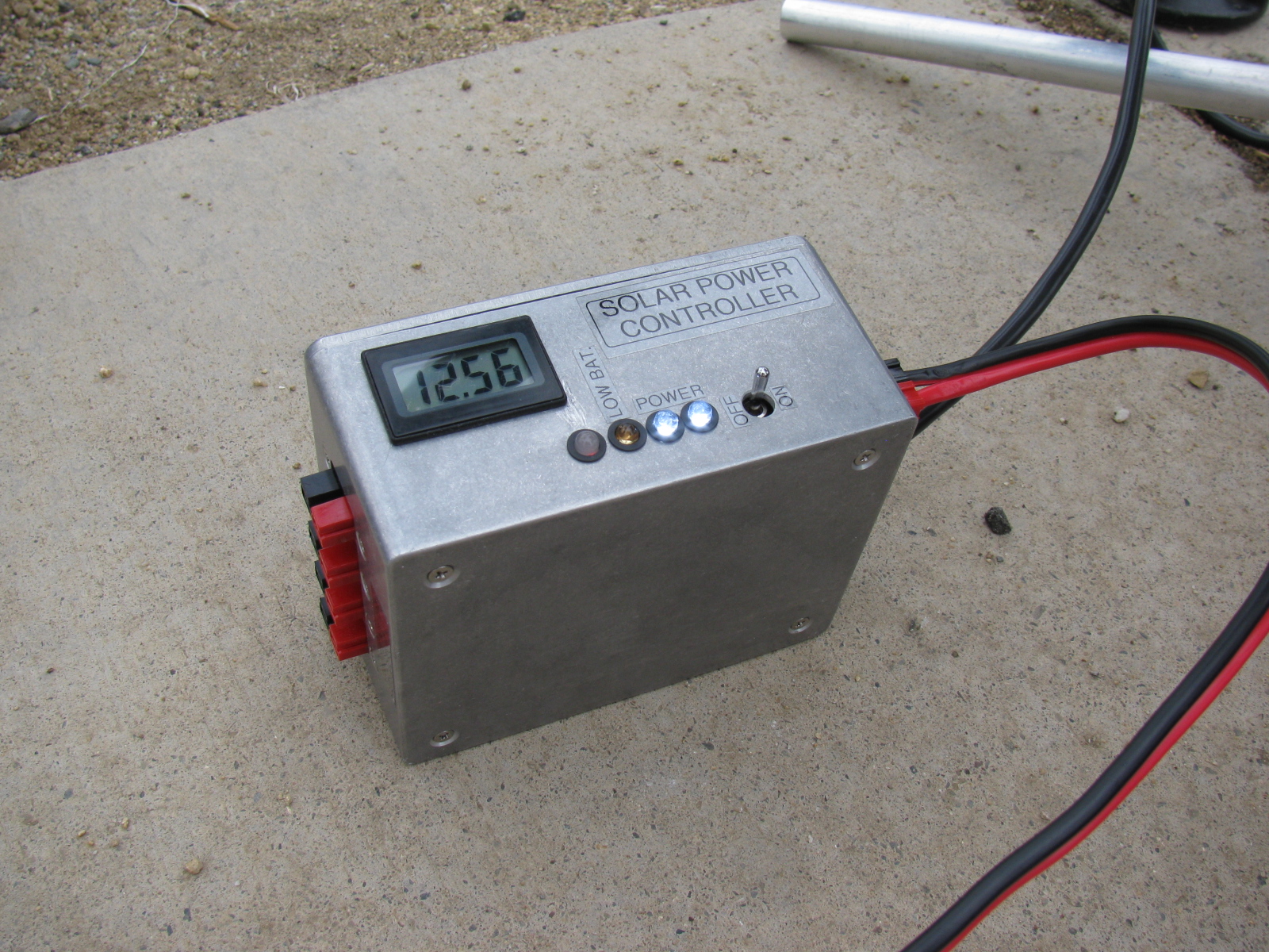
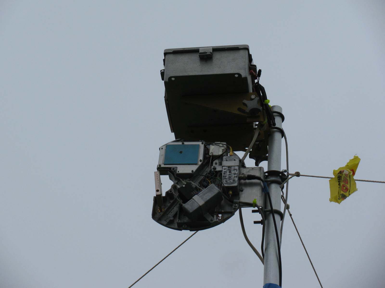
The converter consists of a Frequency West Brick as a 10,223 MHz local oscillator for a mixer used as an upconverter for MDS and down converter for ERP. The converter has a 13 dB horn antenna connected to the mixer RF port. Power is supplied by a 12V battery on the ground with a DC/DC converter supplying the required voltage for the local oscillator. The coax used is 300 feet of RG-59 which was readily available. No attempt to correct matching losses for the 75 ohm coax has been made. The loss of the coax and mixer as well as the amplifier gain was measured at the operating frequencies. It is not really necessary if only relative measurements are to be performed but it does allow a good comparison between measured and calculated values.
The results of the test are entered into a spreadsheet, which then calculates the ERP based on dish size in inches and estimated PA output of the radio under test. The distance in feet from the radios to the converter is input to the sheet, which then calculates the path loss in dB. For ERP, the sheet provides calculated ERP, measured ERP and the difference between them. For MDS at this time, only the signal generator level is recorded and is used for relative measurements.
Block diagrams for the 10 GHz and 24 GHz units are described in the PDFs below:
10 GHz ERP-MDS Block Diagram
24 GHz ERP – MDS Block Diagram
Intro to the MDS/ERP Event Results
(From an entry on the SBMS website on August 10, 2012)
These spreadsheets show the results of workshops/picnics where amateur microwave stations were compared on a unique test range for both transmitting and receiving performance. The test setup was developed by Kerry Banke, N6IZW and has been used by the San Diego Microwave Group (SDMG) and the San Bernardino Microwave Society (SBMS) over the past few years. The test setup consists of a remote TX/RX transmitter/sensor unit installed on a pole about 15 ft. high at a distance of approximately 220 ft. from the stations being tested.
The remote transmitter produces a stable signal on the operating frequency, such as 10368 MHz. Operators tune this in with their rigs and peak their antennas. The signal is then reduced in level until barely discernible (MDS). That level is logged. The operator then transmits with maximum CW power and the RX sensor power level is logged. The spreadsheet is used with the logged data and with data on each rigs claimed antenna size and transmit power to allow comparison of measured versus expected performance.
The results have been useful, not from an absolute basis, but by allowing operators to compare their rig’s results against other amateur’s rigs having similar TX, RX, and antenna characteristics. Any major performance differences between systems can help focus on problems that can be solved before upcoming contest events.
In past events, operators have discovered problems with relays, cables, connectors and even non-functioning power supplies.
Interpreting Results
Receive (MDS) performance is shown in the column marked “MDS Gen dBm.” You want the largest negative value compared to other stations having the same size or performance antenna on that frequency band.
In the last column marked “Meas-Calc,” transmit ERP performance is shown. A zero means that the ERP came out exactly as expected given the claimed transmitter power and antenna gain. A positive number indicates an ERP that is better than expected by that many dB. A negative number indicates system performance measures worse than expected.
Here are some results over the past years – 2013 results added!
TuneUp2013
SDMG ERP-MDS-2013 Results
TuneUp-2012
TuneUp-2011
TuneUp-2010
TuneUp-2009
Tune-Up-2008
TuneUp-2007
TuneUp-2006
TuneUp-2005
TuneUp-2004
TuneUp-2003
TuneUp-2002
TuneUp-2001
TuneUp-2000
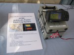
KH6WZ APRS Unit Two (KH6WZ-5)
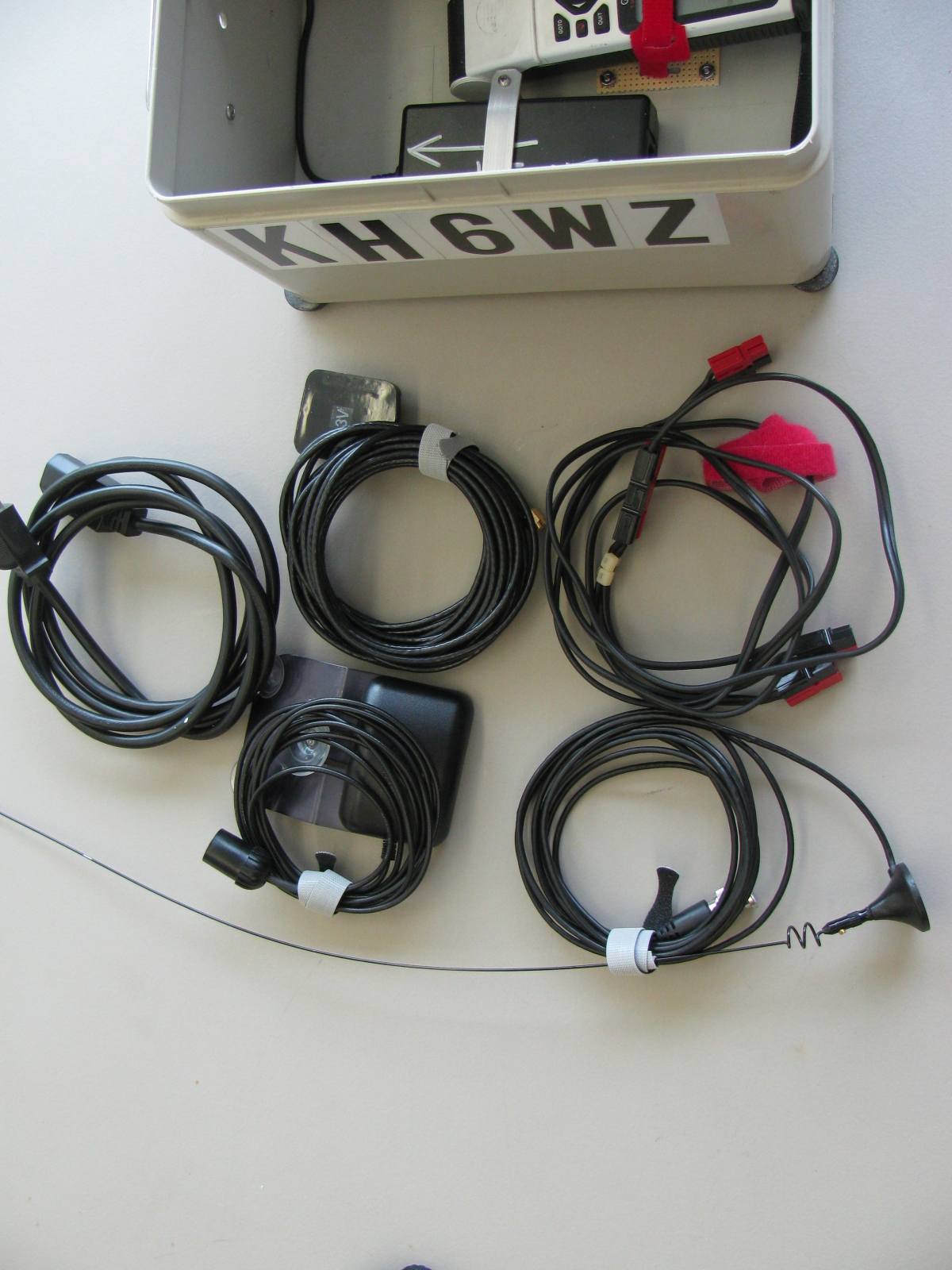
My “high power” version of the tracker box is complete. This unit is housed in an aluminum instrument case, and uses a mobile radio (Radio Shack HTX-252) with 10W and 25W capability for remote locations. The GPS unit is an old Garmin Street Pilot Color Map.
The bottom of the box (on the left) is used to store cables, the original microphone in case I need to use it as a “radio,” a GPS and a two meter whip antenna. A gel-cell would fit nicely in this space for “truly portable” operation.


After Field Day and the demonstration at the Discovery Science Center in Santa Ana, CA last month, I decided to add information on my TinyTrak APRS units on this site.

I re-packaged the unit to simplify deployment and to make it more practical for a “grab and go” event. On the left is a two meter (144MHz) hand-held radio, with the battery pack removed, and powered by external 12V via the DC IN jack. The TinyTrak 2 is next to the HT, in a die cast aluminum case (Hammond 1590B). On the bottom of the box is an old Garmin GPS 45XL and a 12V wall-wart type AC power supply. The bottom of the box also stores a magnet mount antenna for radio, an external GPS antenna and a DC power cable. There’s plenty of room for a gel-cell.


Under Construction
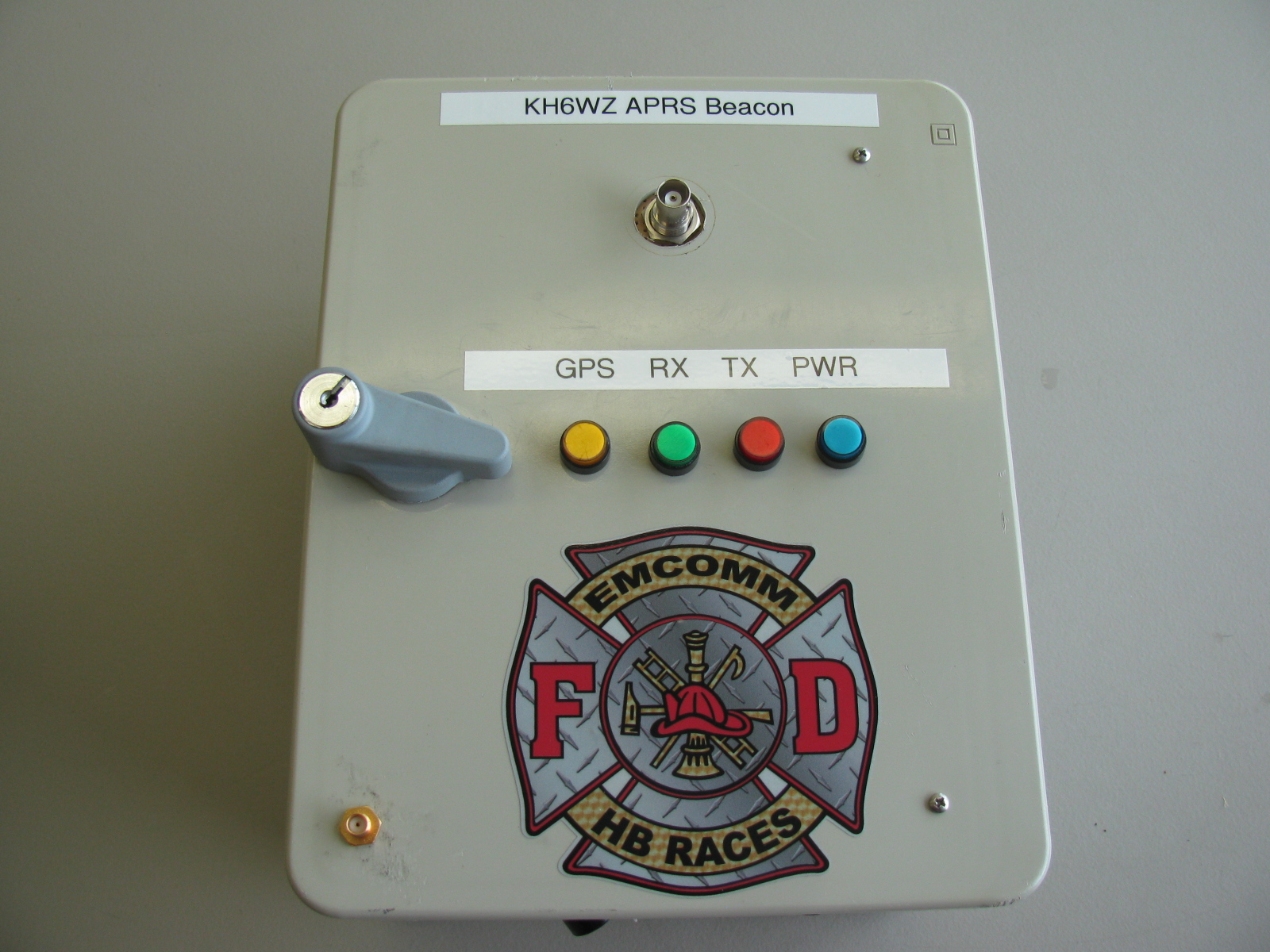
After completing the HB RACES KH6WZ APRS Beacon above, I decided to do a similar thing for my old Garmin Street Pilot. In this version, the GPS unit will be mounted on the outside of the cabinet so the map display will be visible. An inexpensive Radio Shack HTX-252 two meter mobile rig (bought new on a close-out sale years ago) is mounted to the top panel. This unit will be capable of high power operation (10 Watts low power, 25 Watts on high power) to get the signals out in fringe areas. Here are some pictures of the unit under construction. The aluminum chassis box is a surplus instrument case. It is nice and rugged, with a handle on the top.
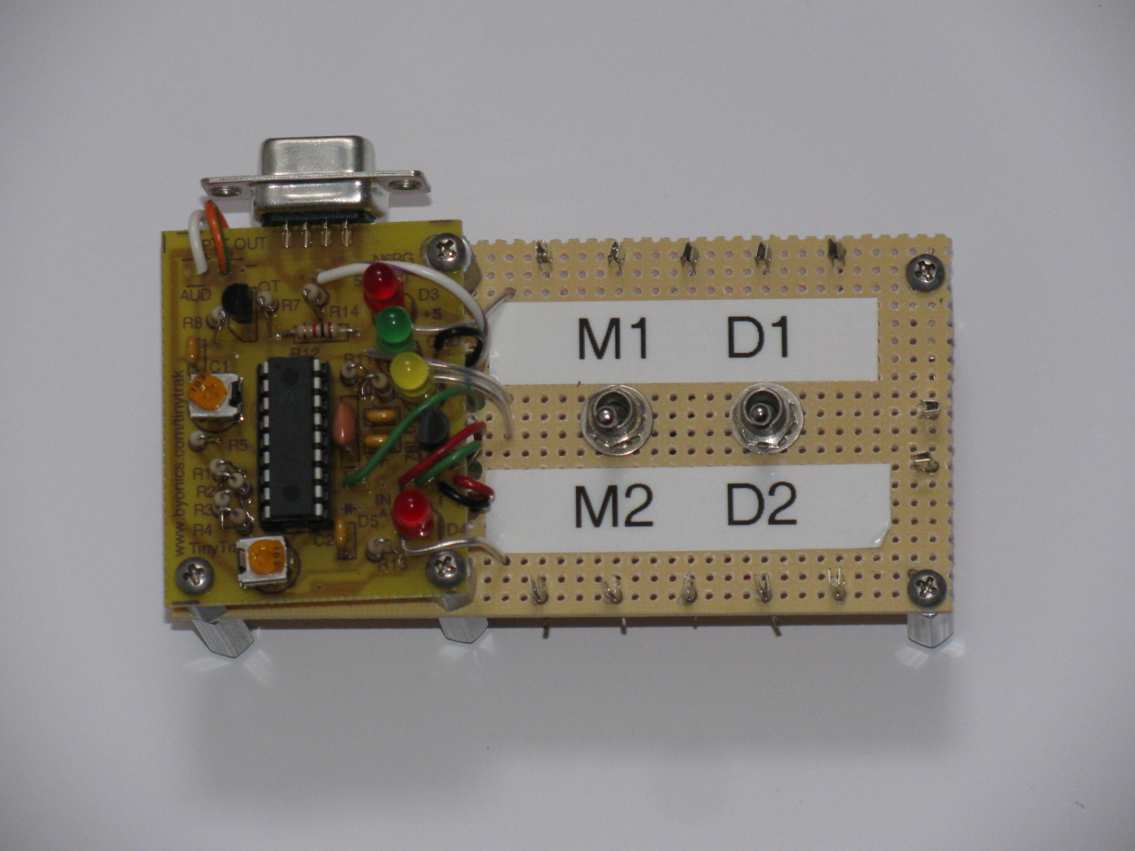
Here you can see the mobile rig at the top left, a row of LEDs to indicate APRS status, the TinyTrak unit and a small perf board with RCA jacks for the GPS signals coming out of the Street Pilot.

Here is a close-up of the TinyTrak PCB and a break-out board for the unit. Switch M1/M2 selects the primary or secondary message programmed in the TinyTrak; switch D1/D2 selects internal display (D1) or the external display (D2). More details on these functions appear below in “One Way to APRS Beaconing.”

Here is a bottom view of the TinyTrak motherboard…. Mounting the TinyTrak this way will help preserve the PCB trace pads and should help simplify access to the wiring when and if it needs repair.

The following information is based on my original article called “Where in the World – A Look at APRS” in the CQ Magazine Beginner’s Corner for November 2003. Click here to see the table of contents of this issue.
I’ve always been fascinated by those “tracker systems” used in the movies and television. You know, like the scene in the movie “Armageddon,” where the ground controllers are watching each member of the “A” and “B” Shuttle teams. Or the “homer” made by “Q” in the James Bond movie “Goldfinger.” I found an expensive and fake homer here, but it is just a fancy sound maker with an LED – take a look at this thing. . .
Today, and in the real world, hams have access to this interesting technology: It’s called the automatic position reporting system (APRS), developed by Bob Bruninga, WB4APR. Basically, it uses latitude and longitude information from the global positioning system (GPS) satellites and transfers the data via packet radio on 2 meters. Mix an APRS station with the Internet, and we have a system in which hams can keep track of moving objects remotely. Interfaced with a suitable weather station, local “micro-weather reports” can be viewed. If you know anyone into APRS, take a look at the N1BQ Web site and plug in their callsign into the search field. You’ll be able to see what he or she has been up to (or at least where they went) lately.
Several members in the local radio amateur civil emergency service (RACES) group made “tracker boxes” and use them for special events, like the Baker-to-Vegas Challenge Cup Relay race. When I saw their APRS systems for the first time, I thought, “Hey, that’s really neat.” Then I went, “Hmmm. What would I do with such a thing?”
Like a lot of hi-tech gadgets, if you think hard enough, you will come up with a lot of reasons to build, buy or otherwise own one. Here are some examples of what you can do with an APRS tracker box:
- When interfaced with a compatible weather station, the APRS beacon can also transmit weather information
- If you are involved with a public service group, you can watch where a person or vehicle is in near real time
- You can re-trace and display your driving, sailing or boating routes via the Internet, and friends and relatives can watch, too
- Put that working but old and un-used 2M HT or mobile radio to good use
Remember that an APRS unit is an Amateur Radio beacon, and must comply with FCC Rules on Beacons, One Way Transmissions, Station Identification and Stations Under Remote Control.
In order to have a moving APRS station, you will need a 2 meter station (rig, antenna, power source), a terminal node controller (TNC) with APRS capability, a computer and a GPS unit. If you are doing packet radio now, or have some packet gear in the closet someplace, you are already more than half way there. By the same token, if you enjoy boating or camping, you may already have a GPS unit.
2013 UPDATE: Many VHF mobile rigs – and some HTs too – come with an APRS capability either built-in or have this feature available as an internal option. This is pretty amazing and shows how fast technology can change.
Here are some notes about what you need to make a simple APRS beacon.
The GPS Receiver and Antenna
The GPS unit does not have to be new – and, in fact, older units might actually be better, since the newer units have gone to the small MCX and other exotic connectors, rather than the easy to use and adapt BNC or SMA connector. I use an old Garmin GPS 45XL and a Street Pilot Color Map, both units have been discontinued many years ago.
Almost any GPS receiver can be used for APRS, but a critical feature the GPS unit must have is a connector port for serial data output in the National Marine Electronics Association (NMEA) format. Just about all “camping” and “marine” GPS units have this data interface.
I suggest looking for the following features, in this order of importance:
1) Ability to access the GPS data output via a serial port. Check to see if the data interface cable is available, or can be easily made or modified. See an interesting alternative source for Garmin-compatible accessory plugs in the Reference section.
2) Ability to use an external antenna. In essence, all GPS units are radio receivers, and, just like your radios, require a good antenna for the best performance.
I have found amplified GPS antennas on eBay and other places for as little as $20. Some GPS modules include a patch type antenna built-in. This may or may not be optimum for use in the field, but today’s GPS units have much more channels than the 10-plus year old units I am using for my system.
3) Ability to apply external 12VDC power. Small penlite cells can get expensive after a while, so the ability to plug into an alternative power source would be good. Be aware that some units need a power source lower than 12V to 15V, and can be damaged if 12V is applied directly to the unit. But do not fret, if your GPS unit needs something other than 12V, you can build or buy a suitable voltage converter to handle this. The simplest way to use external power is to see if the unit has a cigarette lighter accessory or some other external DC cable, and use that. For non-automotive use (like pedestrian mobile), you can remove the cigarette lighter plug and use a gel-cell or other 12V power source.
Garmin seems to be the most popular GPS units for APRS. I think their excellent customer service contributes to this, based on personal experience.
Full-featured GPS units might be a bit extravagant for just APRS applications, so if you are not into flying, backpacking, sailing or other activities requiring navigation, you might want to consider a GPS “module,” rather than a GPS “receiver.” The GPS module is just a “plain data receiver box” with no display, and is intended for use with some other gadget, such as a computer. Because no other “support electronics” is involved, prices for GPS modules are much cheaper than GPS navigation units.
The Interface and the Rest of the Components
An APRS interface is the “brain” that transfers the digital location data from the satellites and instructs the radio transceiver when to transmit and when to receive. More sophisticated units can interpret more GPS information, and transmit more than simple latitude and longitude. For example, on a moving vehicle, the APRS unit can send not only position, but also speed, rate of climb or rate and direction of turn, altitude, a station identifier and an icon.
There are dozens of different symbols used in APRS to indicate what sort of object is being tracked. For example, my friend Peter Barbour, N6RAS, is an avid sailor, and uses a boat icon when he is “beaconing.” Bill Honeyman, KG6CNL, uses a jeep, and Steve Graboff, W6GOS uses a “running man” symbol during the Baker to Vegas race. The eye icon was used during the demonstration at the Discovery Science Center, see the screen capture below.

One Way to APRS Beaconing
There is a simple way to try APRS. The TinyTrak unit, by Byon Garrabrant, N6BG, is a wonderful little circuit that eliminates the packet TNC. If you have a “TT,” all you need is a GPS receiver, a two-meter radio, antennas for the GPS and radio and a power source. The unit is configured via the serial port in your personal computer.
Now in its fourth generation, the TinyTrak units are available in a “fully-assembled” version, complete with a small 2 meter transceiver. The older generation small PC board versions of the TinyTrak are still available.
My units vary somewhat from the “out-of-the-book” instructions. I added an SPDT, center-off toggle switch to make a “test” function: In the test mode, the unit is powered up normally, and the LEDs blink to verify operation. After checking the blinking lights and verifying the two meter rig transmits data, the switch is thrown into the “operate” mode, which simply cuts off the ground connection to the LEDs (making them go off) to conserve battery power.
I recently added another modification: I added another SPDT switch (not center-off) so I can select either the small internal LEDs or the large front panel mounted LEDs when the unit is in operation. This is done to create a “light show” to attract attention during demonstrations.
Remember that the TinyTrak is a simplified beacon device. It will not receive and decode APRS data for display purposes. It is the “data transmitter beacon” or “homer” part of an APRS set up, but they are fun nonetheless.
Once you get your APRS beacon going, I am sure you will want to do more. In the meantime, the simple starter system will enable you to beacon your position while you do your favorite radio-activity, from public service to outdoor events. James Bond’s homer technology is here for hams, and is an exciting and interesting bit of technology we can use just for kicks or for serious public service assistance.
Links to More Information
General APRS info
http://web.usna.navy.mil/~bruninga/aprs.html
http://www.aprs.net
http://www.tapr.org
APRS Symbols
http://www.aprs.net/vm/DOS/SYMBOLS.HTM
See Beacon Locations on the Internet
http://www.wulfden.org/APRSQuery.shtml
TinyTrak “TNC-less” APRS kits
http://www.byonics.com
Carter, Jim WB6HAG, “Build an APRS Encoder Tracker,” QST, February, 2002, page 28
GPS Modules
http://www.makershed.com/default.asp
An Interesting Connector Source for Garmin GPS Units
http://pfranc.com
Baker to Vegas Challenge Cup Relay
http://www.bakervegas.com
The ARRL 10GHz and Up contests are coming up soon (August 17 to 18 and September 21 to 22), so I thought I’d re-publish my article that originally appeared in The Proceedings of Microwave Update 2005.
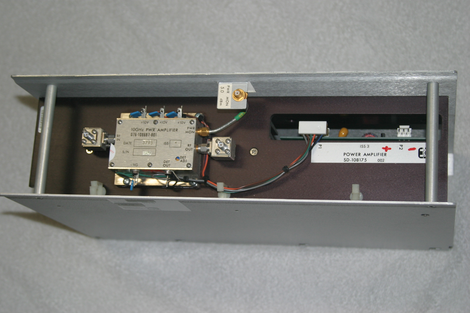
The Harris-Farinon Model SD-108175 / 076-108687-001 solid state power amplifier (SSPA) has been seen globally on the surplus market over the last few years. This amplifier is a part of a large rack of equipment running on the traditional 24VDC, positive ground telecom power system bus.
In its original form, the amplifier is very robust and heavy, since it is rated for continuous duty, Class A operation. Figure 1 shows the unit as received. It is mostly heatsink, and the RF unit, where the microwaves are amplified, is the tiny silver box on top.
The SSPA unit (Model SD-108175) measures about 15-1/2 inches wide, 4-1/4 inches high and 10 inches deep, and weighs over 15 pounds. The little silver box (part number 076-108687-001) with SMA isolators at the input and output, is about 3 inches wide, 1 inch high and 2-1/2 inches deep.
Important: Be careful if you see these units for sale, I have seen some inaccurate descriptions of these units – for ham radio use, the only item we want is just the amplifier (076-108687-001) and not the heatsink/chassis assembly or the power supply DC-DC converter.

Figure 1. The Harris-Farinon 10GHz amplifier is very beefy, but it is mostly heatsink. The little silver box is where the RF is amplified.
I took the unit to Dave Glawson’s lab (WA6CGR) to see if we could integrate this SSPA into my X-band rig. It is a 1W unit, but I have several that put out as much as 3W on 10368 MHz. I purchased several of these units at a very reasonable price, and am pleased with their performance on the 10 GHz Amateur Radio band.
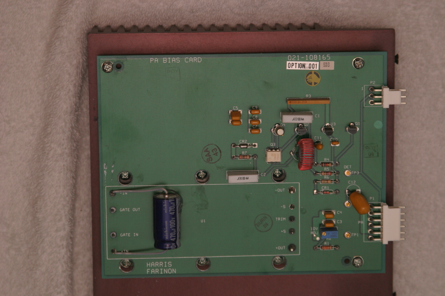
The terminals on the amplifier as well as the power supply PCB are marked, simplifying some of the guesswork about what-goes-where. The amplifier includes a “POWER MON” SMA female jack, which should probably be capped with a 50Ohm termination to prevent oscillations or weird things from happening while the amplifier is operating. A “DET OUT” pin is useful to verify amplifier operation.
It may be prudent to read Chuck Houghton’s article, “Above and Beyond, Microwave Stripline Retuning Procedures” on tweaking circuits before any “poking around” is done on any SHF amplifier, to prevent damage. Links to references are at the end of this article.
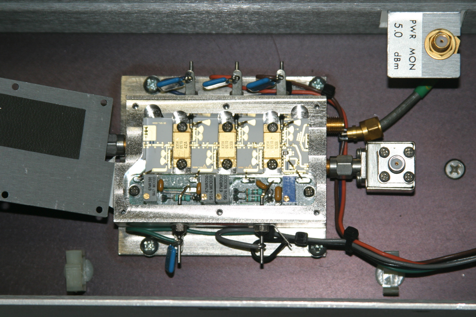
The first step is to power it up and verify operation in its “as-is” state. With about +17dBm (about 60mW) input, power output is about +35dBm, or a little over 3W at 10368MHz. Current consumption is about 2.6A during standby and about 3A at 10V with RF applied. Dave and I wondered whether or not we could tweak the amplifier to get more power out, so we took a look under the lid of the little silver box, see Figure 2. We decided not to tweak anything inside the tiny box.

Figure 2. A peek inside the SSPA. No tuning is required to get two to three watts output on 10368MHz.
Since the amplifier passed its first tests, the next step is to re-package the unit so it would be more suitable for portable and roving operations. Certainly, a weight reduction could be done by shrinking the size of the RF module heatsink, and adding a fan or two.
Since the amplifier passed its first tests, the next step is to re-package the unit so it would be more suitable for portable and roving operations. Certainly, a weight reduction could be done by shrinking the size of the RF module heatsink, and adding a fan or two.
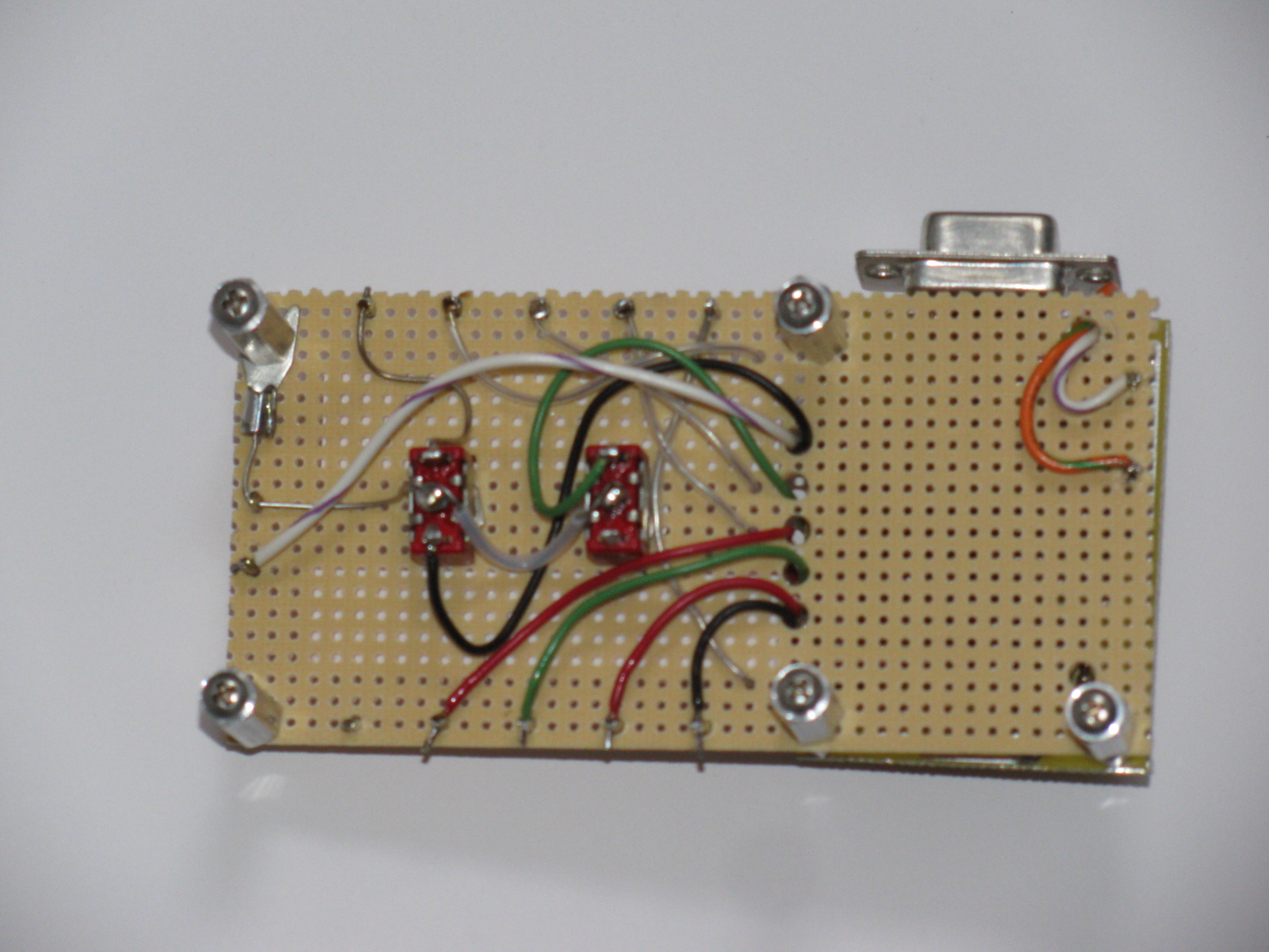
The DC-DC Converter
The original power supply board appears in Figure 3. A casual inspection of the unit showed that the 24V input was buck-regulated down to 12V, and then further reduced to minus 2.1V for the bias and +10V for each stage in the amplifier. The DC-DC power supply looks like it can be modified and re-used, by applying 12VDC where the brick converter has its output. However, this modification was not attempted.

Figure 3. The DC-DC supply board. A 24V to 12V brick converter is mounted to a 14-1/4 inch by 7-1/4 inch heatsink under the PCB. The existing DC-DC converter may possibly be modified to make the unit work on 12VDC input. See text.
I thought a better, lighter, more modern power supply could be built fairly easily, and the large heatsink for the power supply could be deleted.
With Dave’s help, I made a simple DC-DC converter using a Linear Technology LT-1083 adjustable regulator and a few resistors for the +10V supply. The negative bias supply was made from a surplus 99-cent DC-DC converter. I built the power converters into separate chassis boxes, since I had them on-hand. A single box is also acceptable.
Like all FET power amplifiers, one must make sure that the minus (gate) bias supply is always connected before the supply voltage to prevent damage to the devices. I am sure there are several solutions for power-on sequencing to prevent this from happening, including relay or other switching or timing schemes. However, I chose a very simple route: I simply wired the minus voltage directly to the amplifier bias feed-thru capacitor, with no switching in-between. The plus 10V supply line is switched to the amplifier via a power relay, actuated by the sequencer. This way, whenever the rig is powered up, the minus bias voltage is “automatically” applied (it was never off in the first place), and the plus 10V is applied only when the rig is put into transmit mode.
I had a pair of 24V brushless DC motor fans in the junk box, so I am using these to blow on the heatsink. Since I have both 24V and 12V running around in my rig, I wired up a two-speed fan control using a pair of spare relay contacts. When the radio is in the receive mode, 12V is applied to the fans, reducing the noise. When the rig goes into transmit mode, 24V is applied to the fans, running them at full speed.
The final result is shown below. The amplifier is mounted in one of my 10GHz rigs, “Ms. June.” 3 The SSPA puts out 2W at the antenna port, and now measures about 4 inches by 7 inches by 1-1/2 inches, including the cooling fans. A re-labeled, surplus CB panel meter (1mA movement) connected to the DET OUT pin indicates SSPA operation. (Update: Ms. June was cannibalized for parts. However, many of her parts were used in other radios, including my latest, record-setting 10GHz transverter.)

Figure 4. The Farinon SSPA installed in “Ms. June,” one of my early 10GHz rigs. Two watts appears at the waveguide port at the antenna relay in transmit. The DC-DC converters are enclosed in separate chassis boxes, and can be seen just to the right of the amplifier. A re-labeled surplus meter monitors amplifier operation.
References
1 – “Above and Beyond, Microwave Stripline Retuning Procedures,” by C. L. Houghton, WB6IGP, San Diego Microwave Group:
http://www.nitehawk.com/rasmit/mstrp_tu.html
2 – The surplus TDK DC-DC converter is described as a “5V in +/-5V DC/DC converter” at MPJA Online, as part number 1042518. This unit is under a “closeout” deal, so supplies may be limited. Go to http://www.mpja.com, and look under “Power Supplies,” “DC-DC Converters.” Their phone number is 800-652-6733, 9AM to 5PM Eastern Time, Monday through Friday. Although probably not necessary, I removed the TO-220 device from the board and re-mounted it to the metal chassis box for heat-sinking.
3 – Most of the SBMS members have names for their rigs, mainly because, as many of you know, microwave radios tend to have personalities of their own. Ms. June is my sixth 10GHz radio re-build. “Morpheus” was my first attempt, see CQ magazine for December 2003 and January 2004 for my dubious start on the microwave bands.