
Announcing San Diego Mini Maker Faire 2013 – Visit the Maker Booth called “Not Your Grandpa’s Ham Radio”
Maker Faire – where art, science and technology crash together!
Announcing San Diego Mini Maker Faire 2013 – Visit the Maker Booth called “Not Your Grandpa’s Ham Radio”
Maker Faire – where art, science and technology crash together!
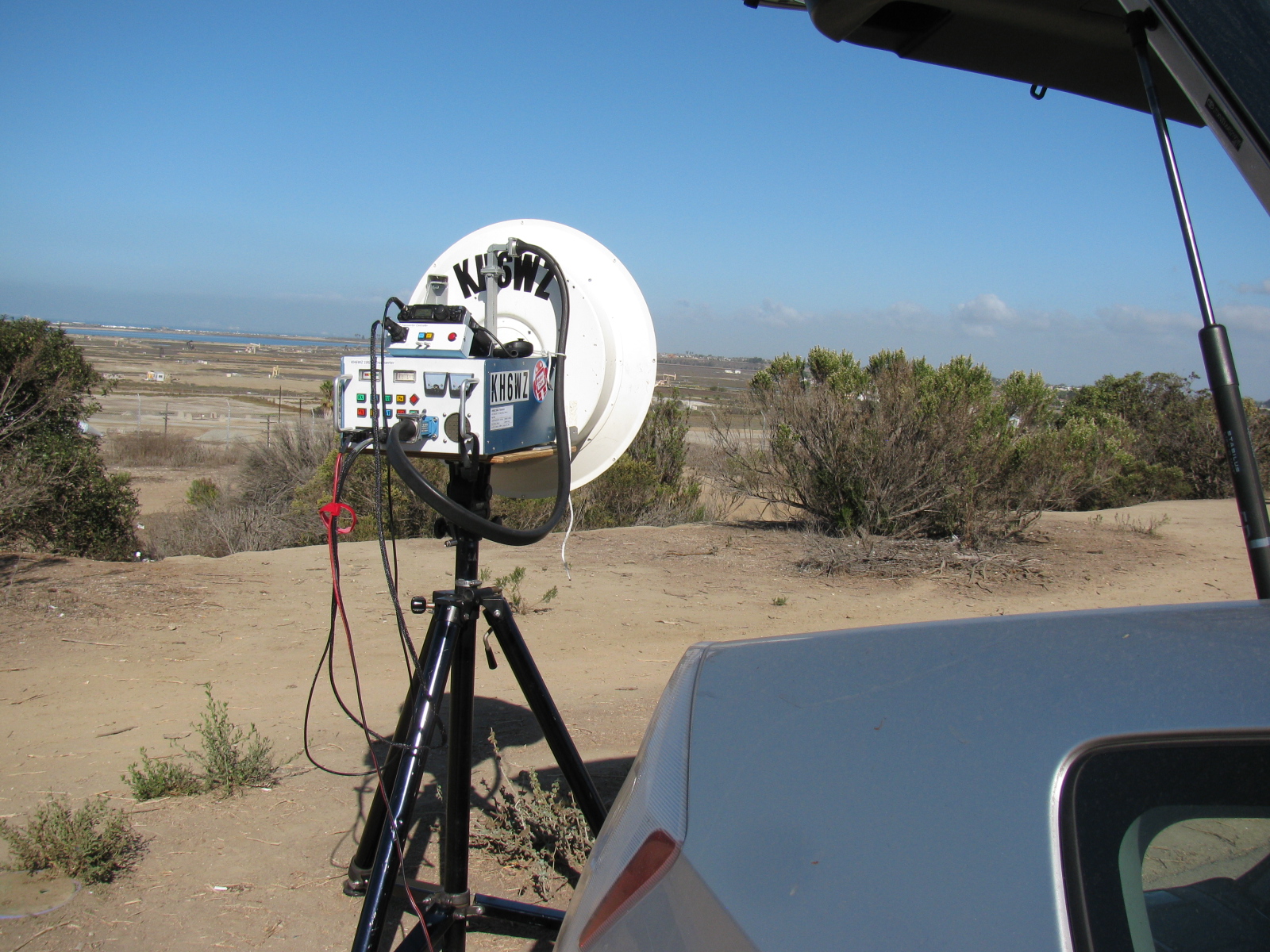
The past weekend was a busy one indeed. I made some time to participate in the microwave contest, dragging my rig out to the bluff overlooking the Bolsa Chica Wetlands and then to El Segundo. The 10 GHz and Up Contest is unique, since it spans over two weekends, the first part is in mid-August and the second part near the end of September. This gives participants a chance to fix broken rigs and continue to add points to their scores.
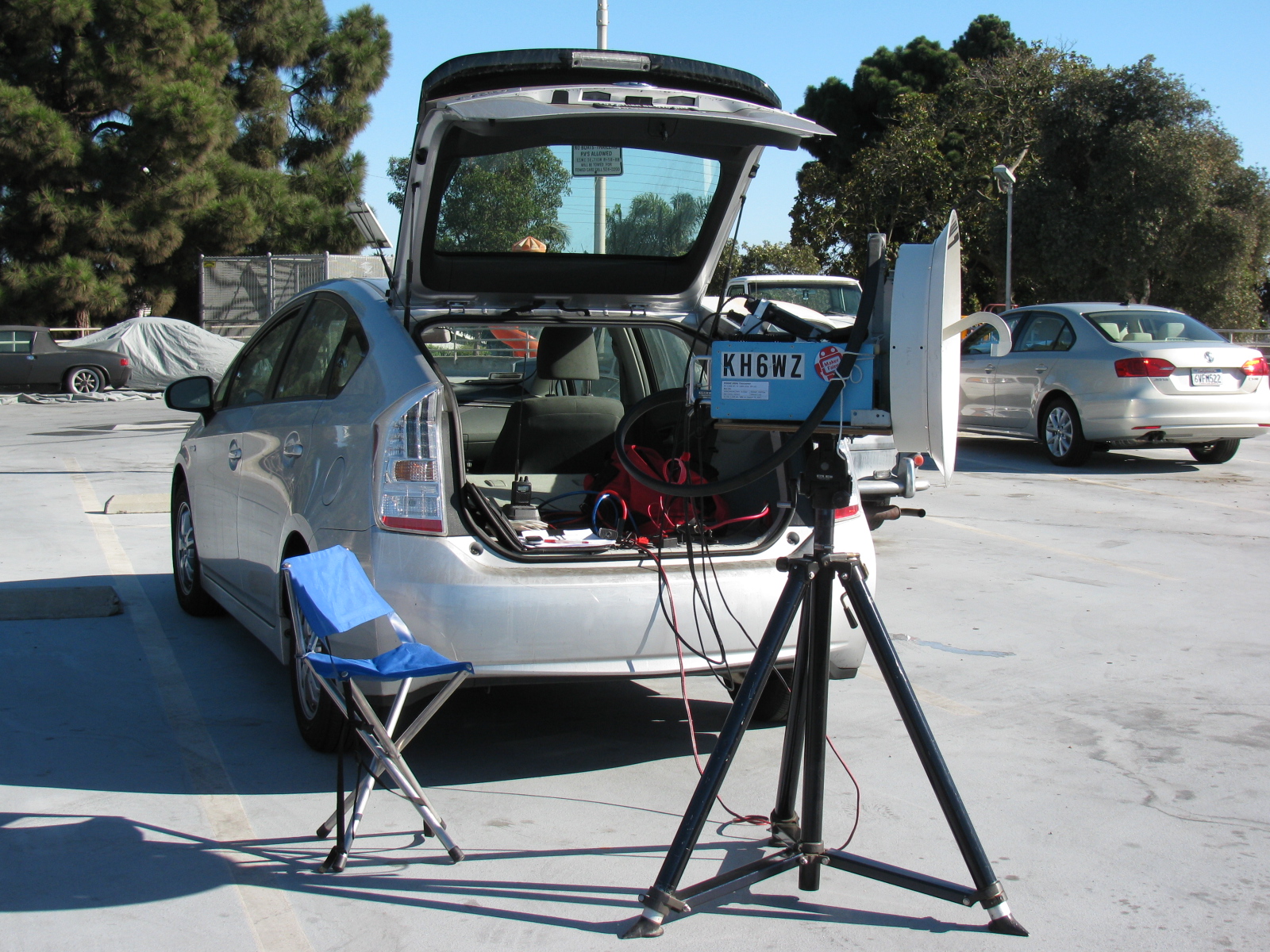
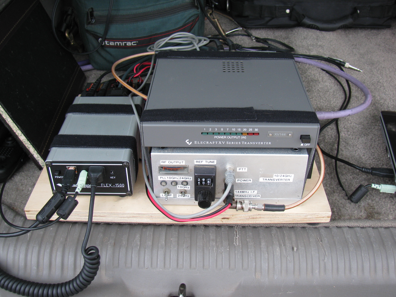
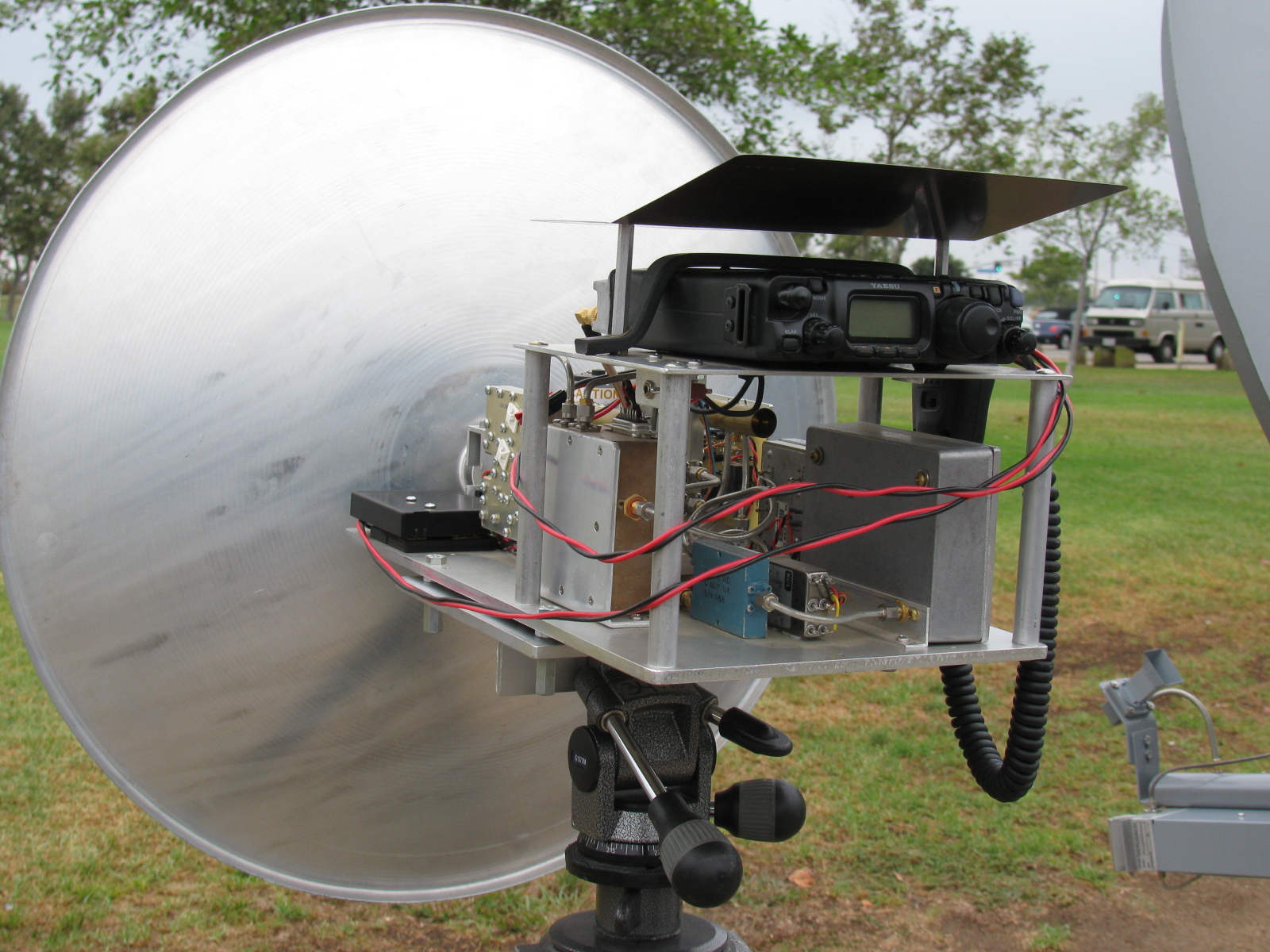
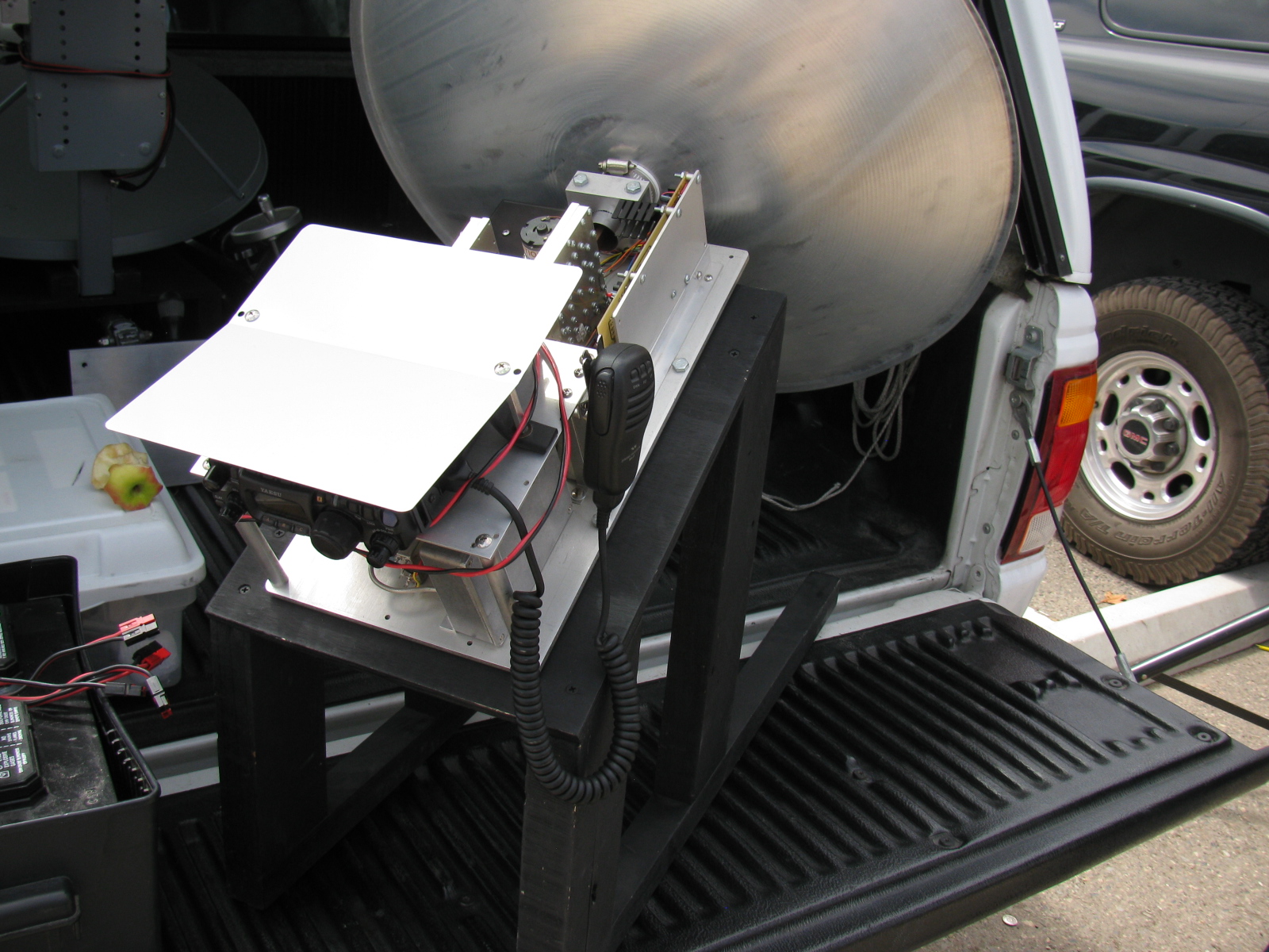
To be honest, I was not prepared for this contest. I did not have any roving plans, my Prius was not modified to supply my 7 watt 10 GHz rig with power and my mobile radio was not programmed with any of the liaison / coordination frequencies. However, I managed to have some fun testing out my homemade 10 GHz (X-band) rig.
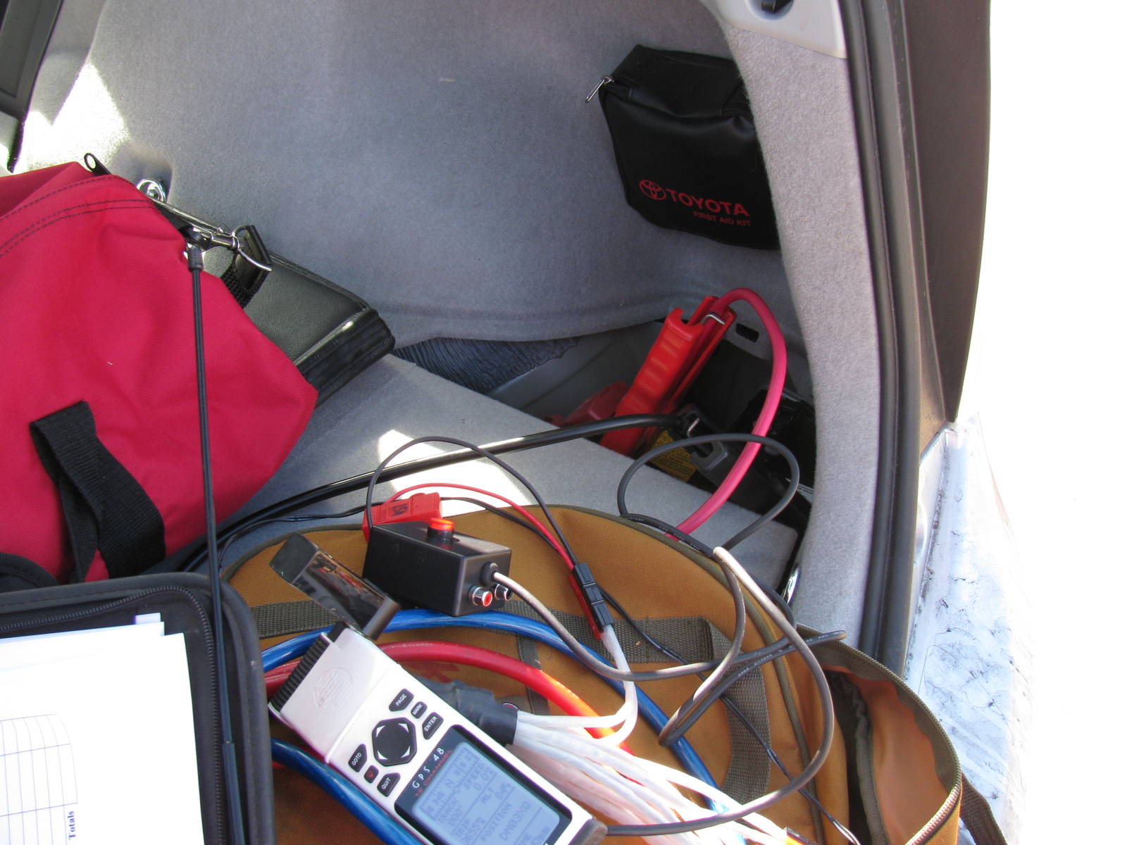
I noticed something during the contest: I was afraid of killing the 12V battery on the Prius, so I left the car on and “ready” during the entire contest. I turned off the air conditioner and the courtesy light. As with normal operation, the gasoline engine will only run when it is needed to charge the system, including the 300V (or whatever voltage it is) traction battery.
Since the rig draws 10 amps in transmit, and transmitting a continuous signal for “beaconing” so that other stations can find me is a routine practice in microwave contesting, I was worried that something might happen to the Prius power system.
However, the car seemed to be fine, and the rig was happy to run under full DC power, producing a clean signal and no “unlock” condition. The engine did start up and ran for less than one or two minutes at a time, and the engine is so quiet, sometimes I did not notice it was on.
Using the Prius as a power system worked out so well that I will eliminate my spare battery idea and mount a power connector on the battery box lid so I can use the DC to power station equipment for the next contest. I have a 100 Ah gel cell battery in a big plastic box that I usually use for radio contesting, so it is independent from the car power system – but I discovered the battery was dead and was not holding a charge when preparing for the Disaster Expo – that is another story. . .
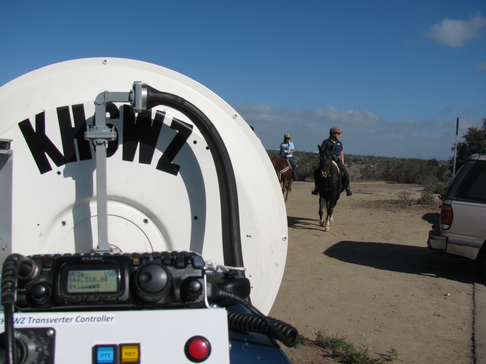
Since I operated from these two locations before, I don’t have too many pictures of these places, but these will give you some idea of what operating a rover station in the 10 GHz contest is like. Well, not really.
My un-official score for about 5 hours of operating time is:
1900 QSO Points + 3341 Distance Points = 5241 Final Score
Best DX is 217 km, when I worked K6NKC and KC6UQH in DM12rr (East San Diego County) from El Segundo, DM03tw
The most fun and challenging contact happened to be my last contact. It was a two-way CW contact with WA6JBD in DM14go (not sure where), from the El Segundo water tower location.
Of the 29 total contacts made, 19 were unique callsigns
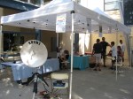
Here are some pictures . . .


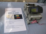
APRS display of the KH6WZ-5 location beacon at the 2013 OC Mini Maker Faire at UCI. Notice the beacon message at the top of the screen capture includes the URL of the event – a great publicity tool!
This past weekend, the second OC Mini Maker Faire happened. And it just so happens to be the second running of my ham radio demonstration called, “Not Your Grandpa’s Ham Radio (2)!” This is my continuing mission to remind people of two things:
First, “The Maker Movement” is nothing new, Amateur Radio operators have been doing this for a almost a century, and nearly 2 million people worldwide are involved in ham radio in some way.
Second, Ham radio is not necessarily an old man’s hobby where weird guys talk to strangers from garages and basements. We are skilled wireless communicators and use today’s technology, from GPS and microprocessors to lasers and microwave frequency linking.
This time I added static and working displays of my various APRS beacons (KH6WZ, KH6WZ-5, and others). I programmed the OC Mini Maker Faire’s URL to the beacon message so people can take a look at what was happening – an excellent publicity tool!
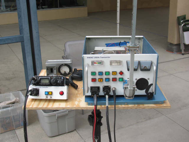
I also planned on making some 10 GHz contacts with my rig, since this was also the same weekend as the ARRL 10 GHz and Up Contest. The transverter covers were removed so people can see the system’s guts.
Based on previous experience at the Discovery Science Center “Meet the Makers” event, I demonstrated radio wave polarization- horizontal vs vertical – with my rig and the microwave strength meter.
Since I had plenty of space, I shared my booth with a company that makes interesting computer and microprocessor related items. This may sound trivial, until you realize this company is run by these three young guys . . .

Huxley, Max and Ethan showing one of their products called the SmartPac.
There seemed to be more people at this Faire, probably since not too many other events were happening nearby. The 405/605/22 freeway closure did not affect the MF, since it started after the event ended.
More than a dozen hams – either active or at least licensed – stopped by to visit. We talked about this event as well as the Bay Area Maker Faire, and what ham radio activities we are involved with.
One more thing: I met several guys from the San Diego area – they are finalizing the plans to have a Mini Maker Faire in the San Diego area – this is great news. Stay tuned and I will announce an update as soon as I hear something from the committee!
Here are some pictures from the event. I am already thinking of building some new displays for next year.


This past weekend, some of the active San Bernardino Microwave Society (SBMS) gathered at Fairview Park in the early morning to perform a field test of their microwave systems. Since I did not do anything with my rigs this past year, I decided to skip this field test, and take some pictures of any new more interesting rigs for this contest season.
Here are some pictures of the various station equipment SBMS club members built and tested that day . . .


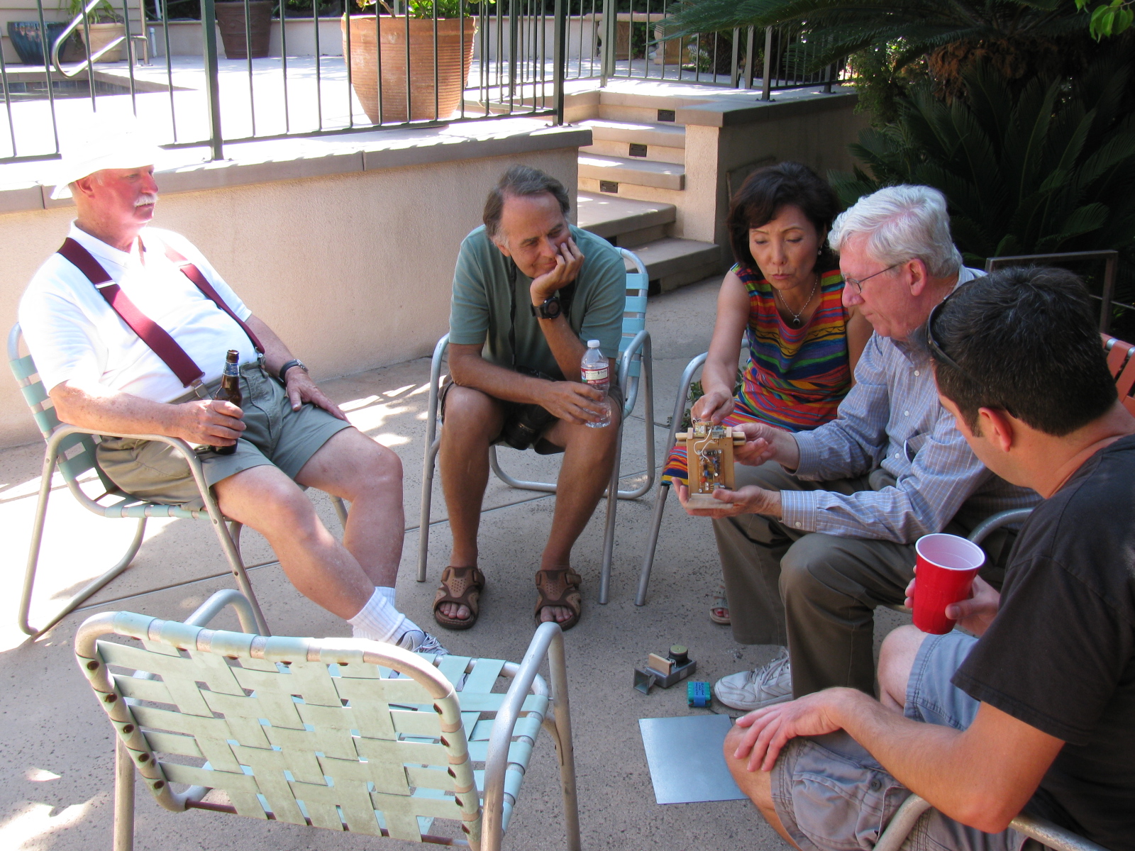
A post-Tune Up Party party and BBQ was held at Dennis W6DQ’s house. It was nice to relax and visit with the other SBMS members and enjoy some great BBQ chicken….. In the picture below, Walt, WALT explains one of his radio wave demonstrations to a captive audience… Watching and learning, from left to right are Bill Preston, KZ3G; Dan Slater, AG6HF and wife Sandy Slater; Walt, and Jason Sogolow, W6IEE.
If you are curious about the test setup, here is an article written by Kerry Banke, N6IZW, with some small edits by me:
Checking Microwave Radio Performance with a Simple ERP/MDS Test Unit
By Kerry Banke, N6IZW (Edited by Wayne Yoshida, KH6WZ)
Before heading for the hills with 10 GHz equipment around contest time, members of the San Diego Microwave Group (SDMG) and the San Bernardino Microwave Society (SBMS) check the Effective Radiated Power (ERP, transmit) and Minimum Discernible Signal (MDS, receive) with the simple setup described in this article. We hold the test sessions at the June and July meetings in preparation for the ARRL 10 GHz and Up Contest in August and September. The advantage to having two sessions is that it provides a second opportunity to verify improvements or allow participation if the first session is missed. The test unit works with both wide band and narrow-band radios.
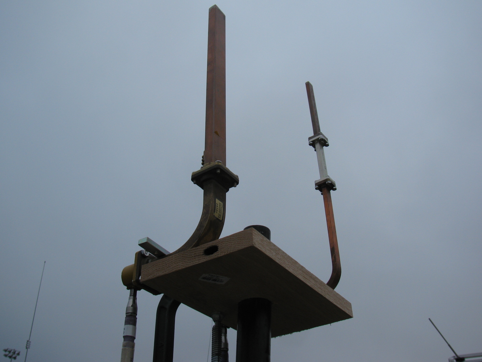
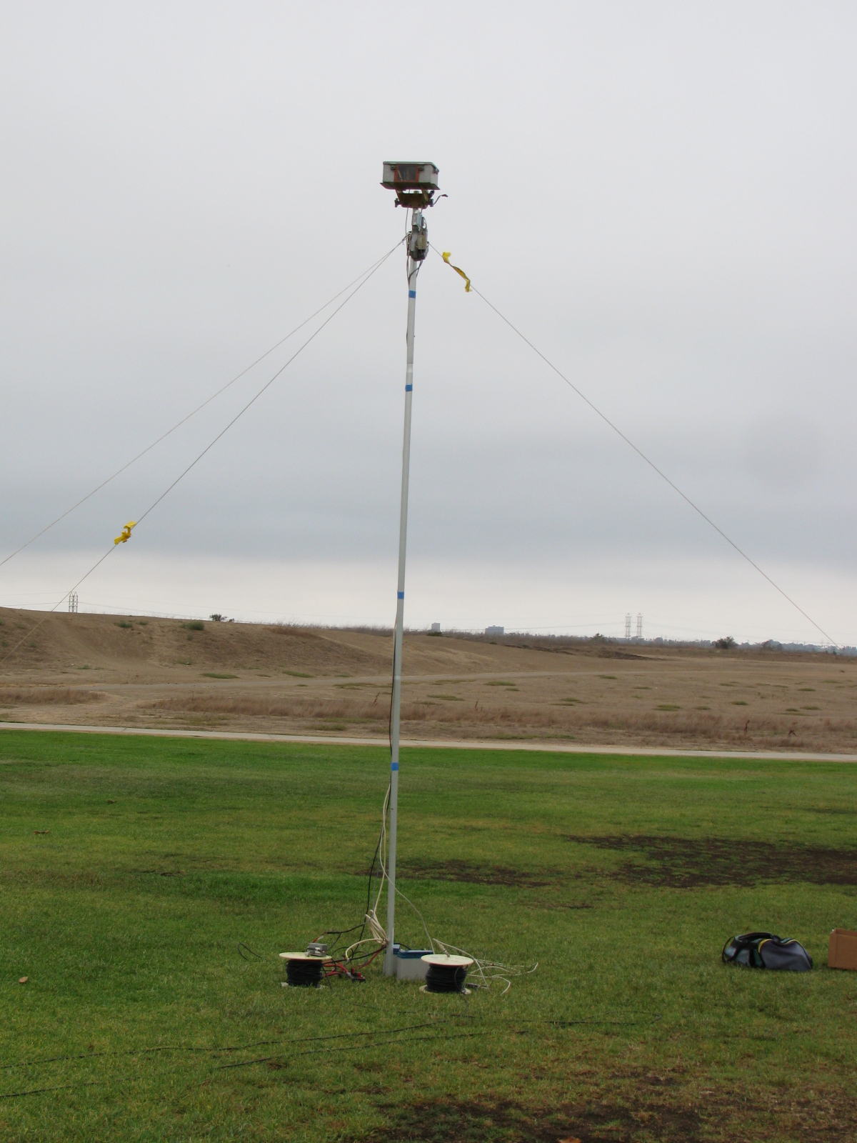
The Pole-Mounted Test Setup
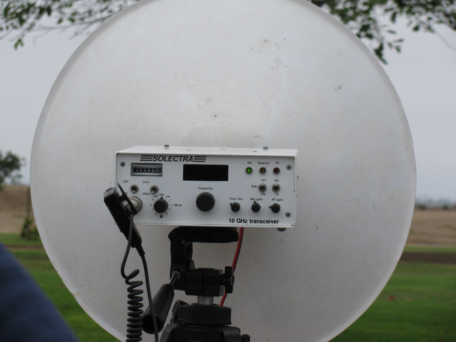
The setup consists of a pole mounted X-Band converter unit connected by coax to a signal source (for MDS) and an amplifier/power meter located near the radios to be tested some 200-300 feet away. The MDS test must be performed first to align the radio antennas with that of the converter. A signal generator is connected to the IF coax and a suitable frequency (145 MHz) and power level (-40 dBm set to transmit an easily detectable carrier around 10368 MHz at the output of the converter.
MDS for Receive
Each participant adjusts their equipment and the system antenna for maximum signal as the power level of the signal generator is reduced to the point where it is no longer detectable by the radios. The level at which the signal can just be detected is considered the MDS.
ERP for Transmit
The ERP measurement is performed by connecting the IF coax to the amplifier and power meter. Each radio transmits one at a time and the power meter reading recorded. The variable attenuator is adjusted to keep the reading in a suitable power range for the power meter and amplifier. For the amplifier used, the maximum output power was about +10 dBm and the power meter range is about –20 to + 10 dBm so the attenuator was adjusted to keep the reading in the –20 to 0 dBm range.
The choice of the IF frequency for the converter depends on what is available for a 10 GHz local oscillator but needs to be low enough to keep the losses reasonable through hundreds of feet of coax. The amplifier gain and maximum output need to be based on the power meter characteristics. The signal generator needs to match the IF frequency chosen, have suitable stability for CW work (NB only), and have variable output (may be an external attenuator).
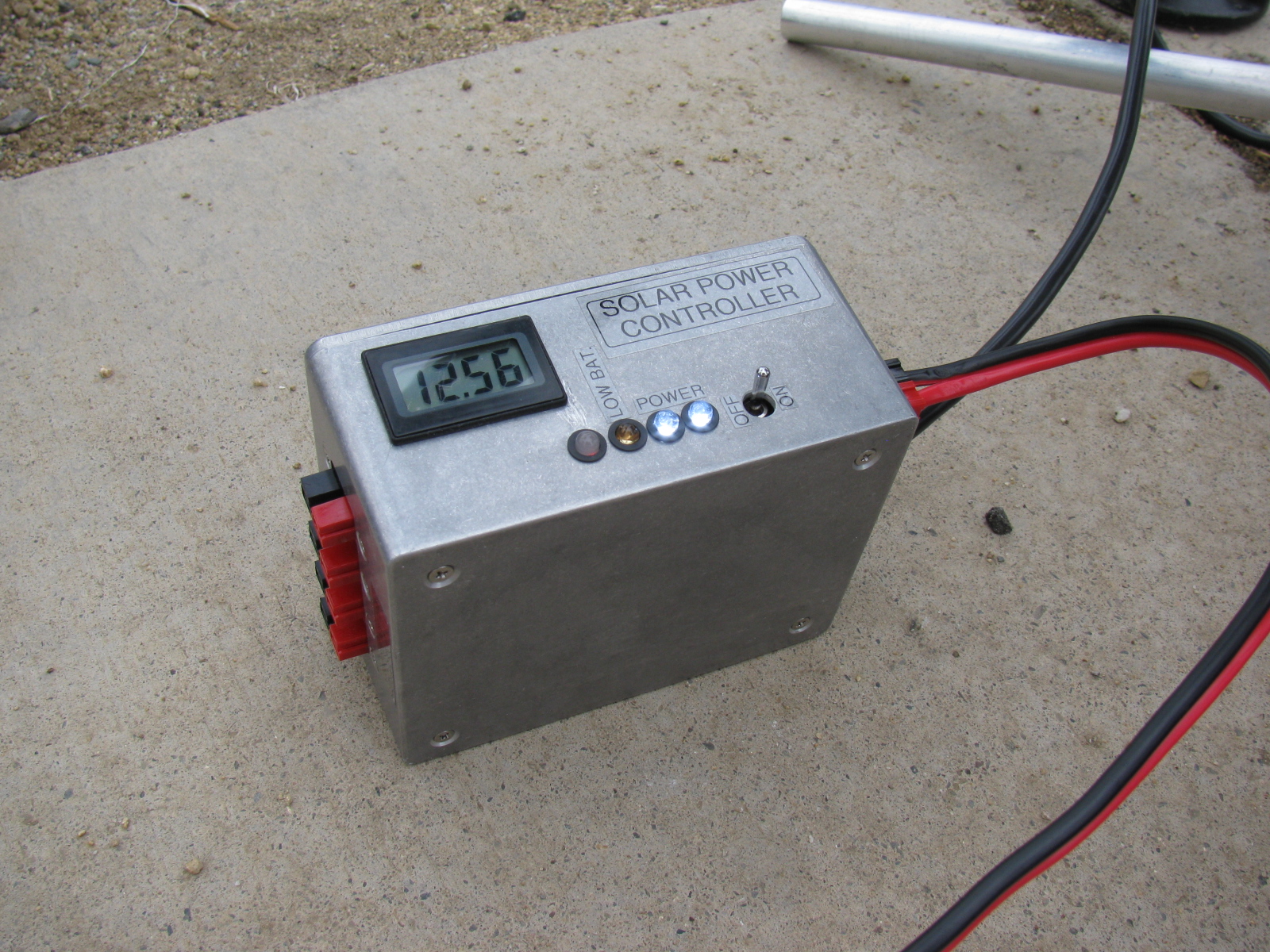
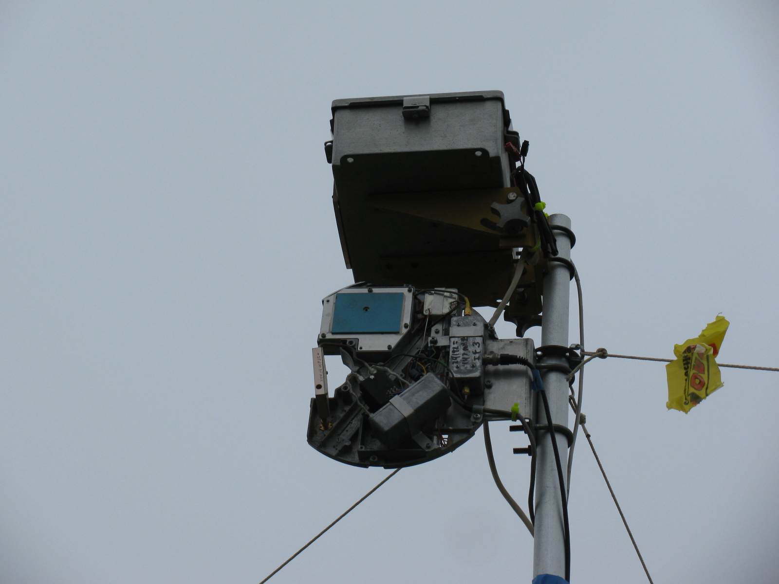
The converter consists of a Frequency West Brick as a 10,223 MHz local oscillator for a mixer used as an upconverter for MDS and down converter for ERP. The converter has a 13 dB horn antenna connected to the mixer RF port. Power is supplied by a 12V battery on the ground with a DC/DC converter supplying the required voltage for the local oscillator. The coax used is 300 feet of RG-59 which was readily available. No attempt to correct matching losses for the 75 ohm coax has been made. The loss of the coax and mixer as well as the amplifier gain was measured at the operating frequencies. It is not really necessary if only relative measurements are to be performed but it does allow a good comparison between measured and calculated values.
The results of the test are entered into a spreadsheet, which then calculates the ERP based on dish size in inches and estimated PA output of the radio under test. The distance in feet from the radios to the converter is input to the sheet, which then calculates the path loss in dB. For ERP, the sheet provides calculated ERP, measured ERP and the difference between them. For MDS at this time, only the signal generator level is recorded and is used for relative measurements.
Block diagrams for the 10 GHz and 24 GHz units are described in the PDFs below:
24 GHz ERP – MDS Block Diagram
Intro to the MDS/ERP Event Results
(From an entry on the SBMS website on August 10, 2012)
These spreadsheets show the results of workshops/picnics where amateur microwave stations were compared on a unique test range for both transmitting and receiving performance. The test setup was developed by Kerry Banke, N6IZW and has been used by the San Diego Microwave Group (SDMG) and the San Bernardino Microwave Society (SBMS) over the past few years. The test setup consists of a remote TX/RX transmitter/sensor unit installed on a pole about 15 ft. high at a distance of approximately 220 ft. from the stations being tested.
The remote transmitter produces a stable signal on the operating frequency, such as 10368 MHz. Operators tune this in with their rigs and peak their antennas. The signal is then reduced in level until barely discernible (MDS). That level is logged. The operator then transmits with maximum CW power and the RX sensor power level is logged. The spreadsheet is used with the logged data and with data on each rigs claimed antenna size and transmit power to allow comparison of measured versus expected performance.
The results have been useful, not from an absolute basis, but by allowing operators to compare their rig’s results against other amateur’s rigs having similar TX, RX, and antenna characteristics. Any major performance differences between systems can help focus on problems that can be solved before upcoming contest events.
In past events, operators have discovered problems with relays, cables, connectors and even non-functioning power supplies.
Interpreting Results
Receive (MDS) performance is shown in the column marked “MDS Gen dBm.” You want the largest negative value compared to other stations having the same size or performance antenna on that frequency band.
In the last column marked “Meas-Calc,” transmit ERP performance is shown. A zero means that the ERP came out exactly as expected given the claimed transmitter power and antenna gain. A positive number indicates an ERP that is better than expected by that many dB. A negative number indicates system performance measures worse than expected.
Here are some results over the past years – 2013 results added!
Some Body Parts, More IRS Conundrum and a New Microwave Antenna for KH6WZ
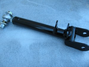
Inspired by a post on the Factory Five Racing forum and the dry and sunny weather this weekend, I decided to paint some of my body mounting parts. I am using gloss black Rust-Oleum Appliance Epoxy paint for these pieces. I have used this paint for my electronic and radio projects with good results. The paint dries very hard and is waterproof and washable, perfect for these parts.
Surface prep is easy for this paint, I scuff the surface with a 60 grit sanding disc on my random orbit sander. For the hard to reach nooks and crannies, I use a wire wheel chucked in my hand drill. Then I use liquid dish soap and water to wash off the grit and any oils. No primer is needed for this paint. Then I apply two or three light fog coats first, and then blast a thick coat for the fourth or fifth and final coat.
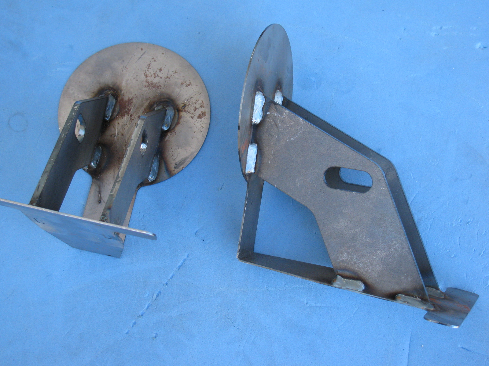
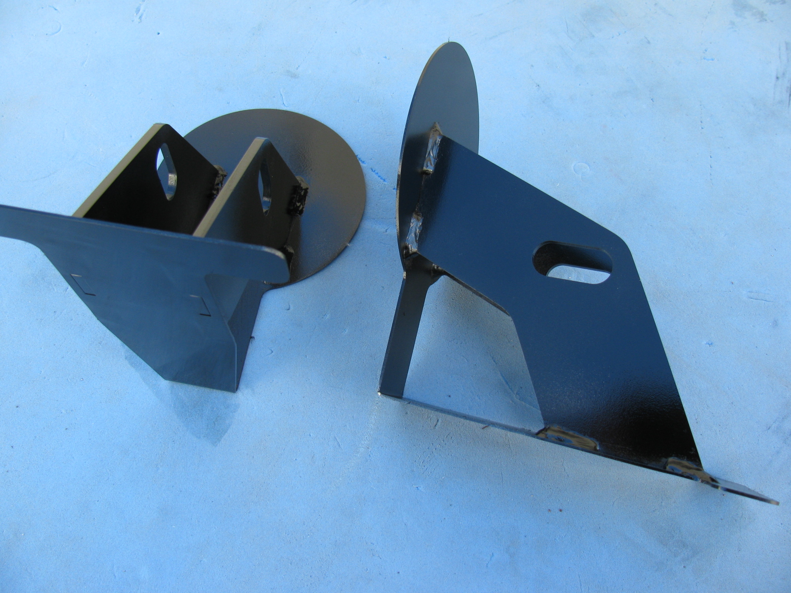
Here is a “before” and “after” picture of the front nose mounting hinge.
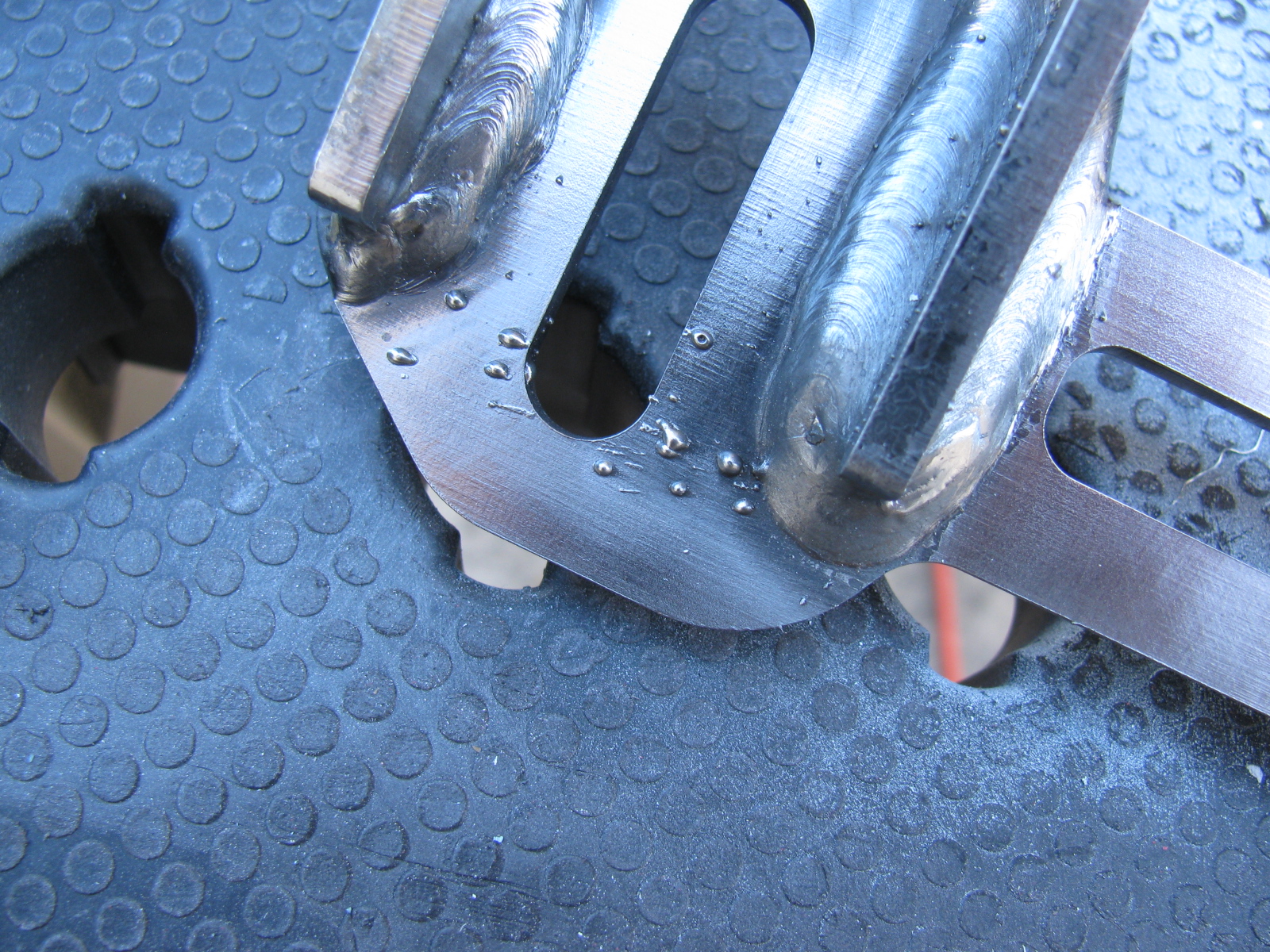
I did the same with the door hinges. Here you can see some weld splatter that will interfere with the mounting bolts, so I used a Dremel tool to grind those weld balls off.
Although many of these parts will not be seen, I do not want them to rust. Other parts will be painted in the same way, and include the door frames, the rear glass hatch hardware and the emergency brake mechanism.
Meanwhile . . .
After spending some time fiddling with the factory-supplied accelerator pedal, I decided to buy an aftermarket gas pedal instead. I ordered one of Russ Thompson’s gas pedals earlier this week from Breeze Automotive, one of the Factory Five Racing Forum supporters. I was amazed the box arrived on Thursday – that was fast!
The new gas pedal is really a machined aluminum sculpture. Pictures on this will be coming later, since I need to get the engine mounted before the gas pedal goes in.
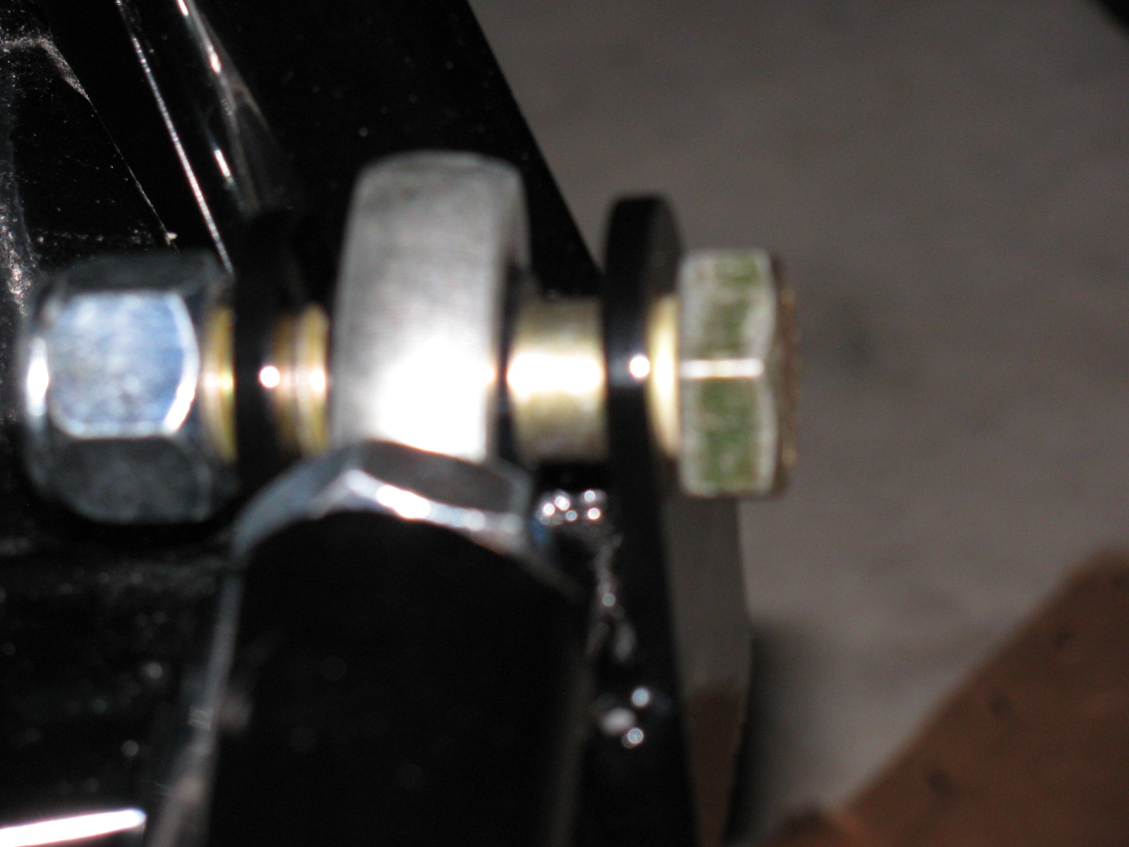
IRS – Finished – Sort Of . . .
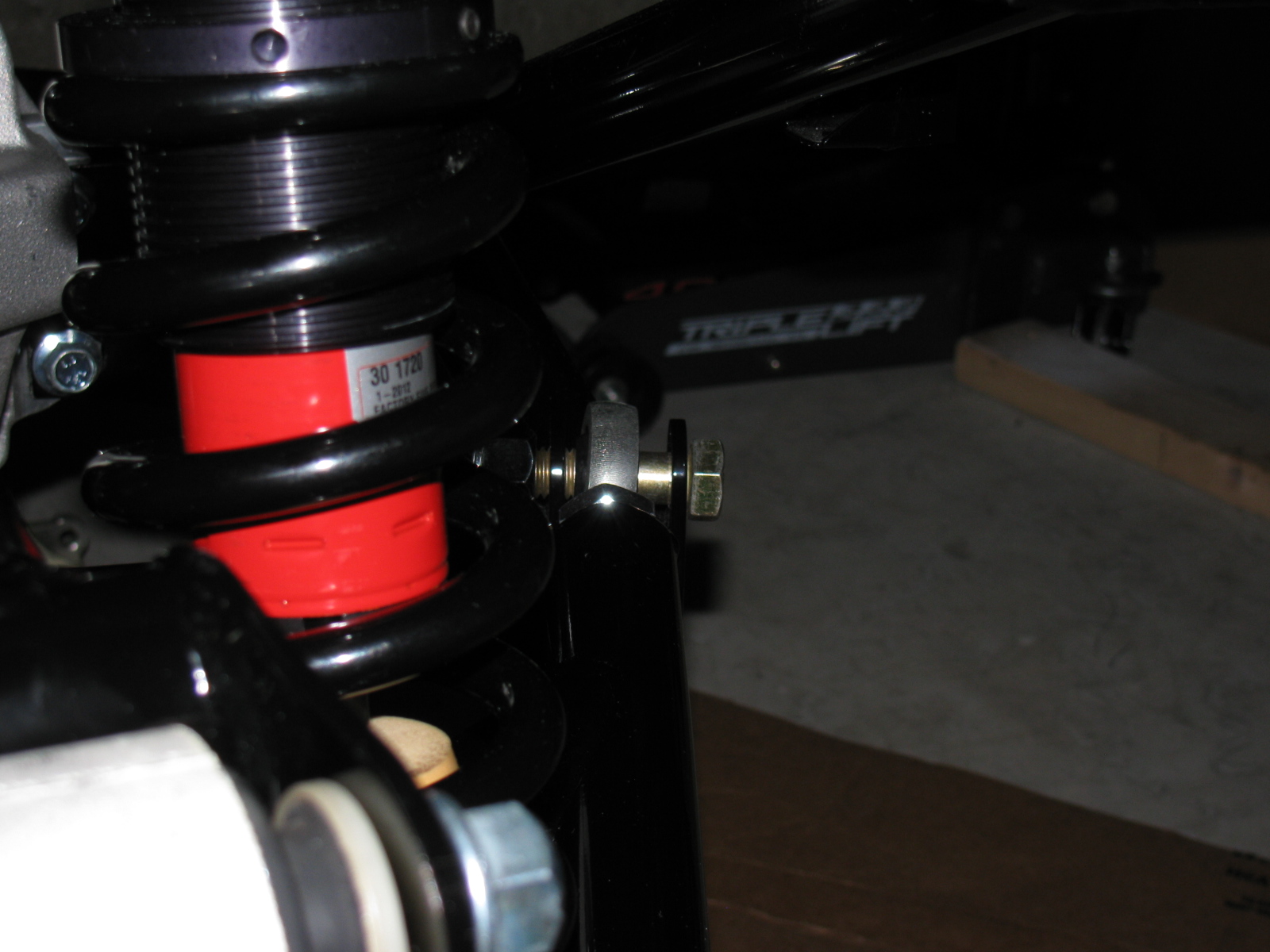
The IRS section is now fully “dry-fit” completed, and the bolts will be tightened to specs in the next work session. One thing that is putting this assembly step on hold are the mounting points for the lower control arms – see the gold color on the right of this picture? That is the mounting bolt and as you can see, there is a lot of empty space between the mounting ear and the thin washer (the manual calls them shims). This cannot be correct, and I need to find what is wrong here. . . .
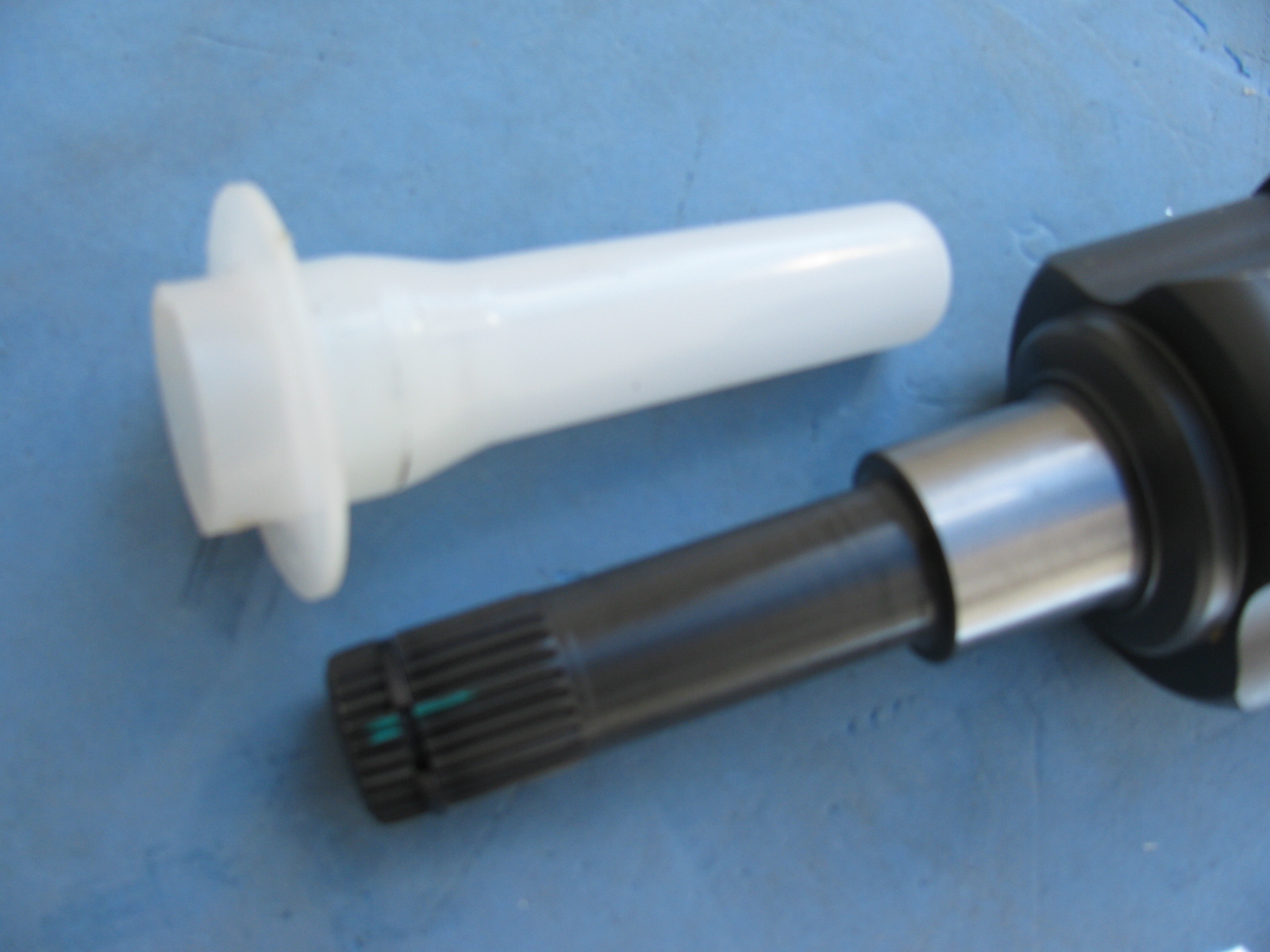
Just after I ordered my Type 65 Coupe kit, I came across a lot of posts on the forums about the IRS shafts (CV joints) coming apart. Those messages made me worry, but when my kit was shipped, the CV axles were on back-order. I called Factory Five Racing technical support, and they assured me that the problem has been fixed.
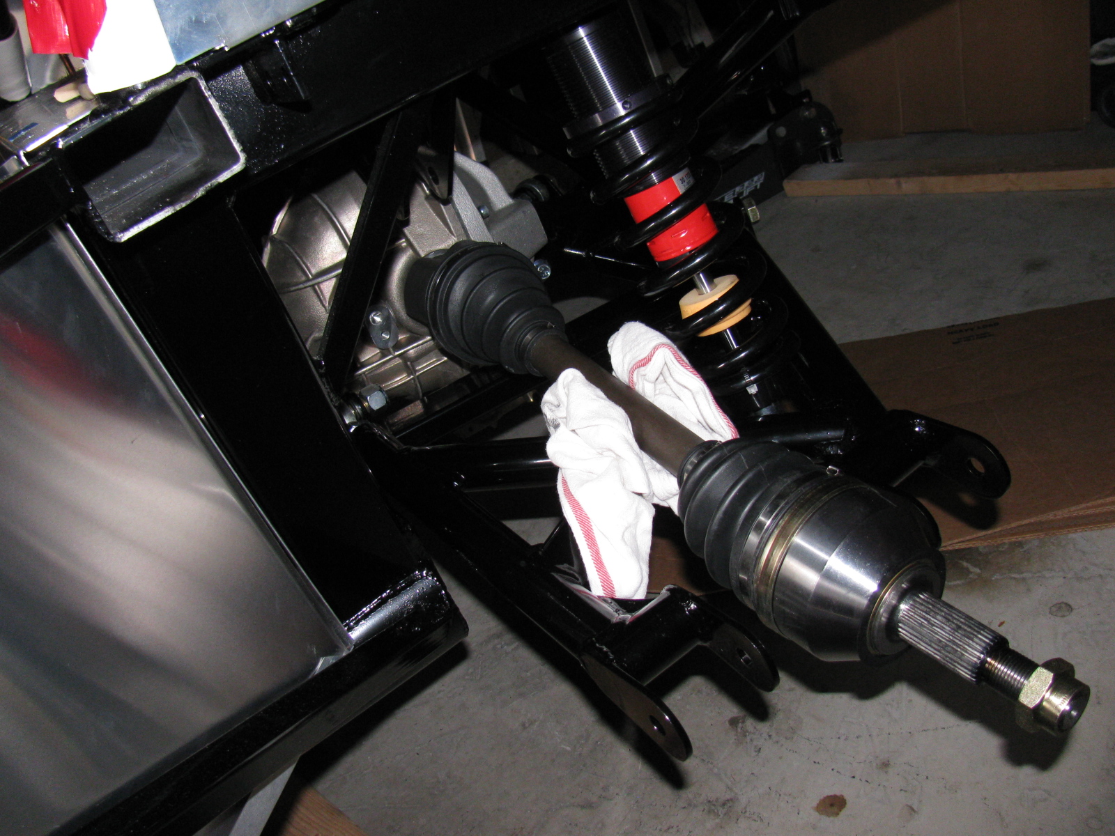
I am happy to report that my IRS system assembly went very smoothly, after the pumpkin was in place. The CV axles slipped right into the differential, and it felt just like many posts said – you can feel it lock into place. No hammering, no drama and no R- and X-rated words necessary.
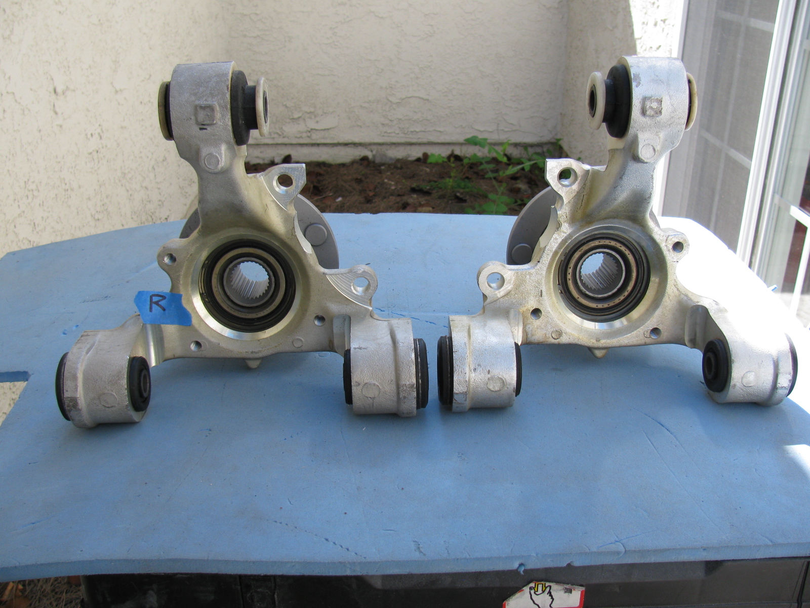
Once again, Chris comes to the rescue by posting images of the IRS knuckles and which part goes on the left side and which one goes on the right side.
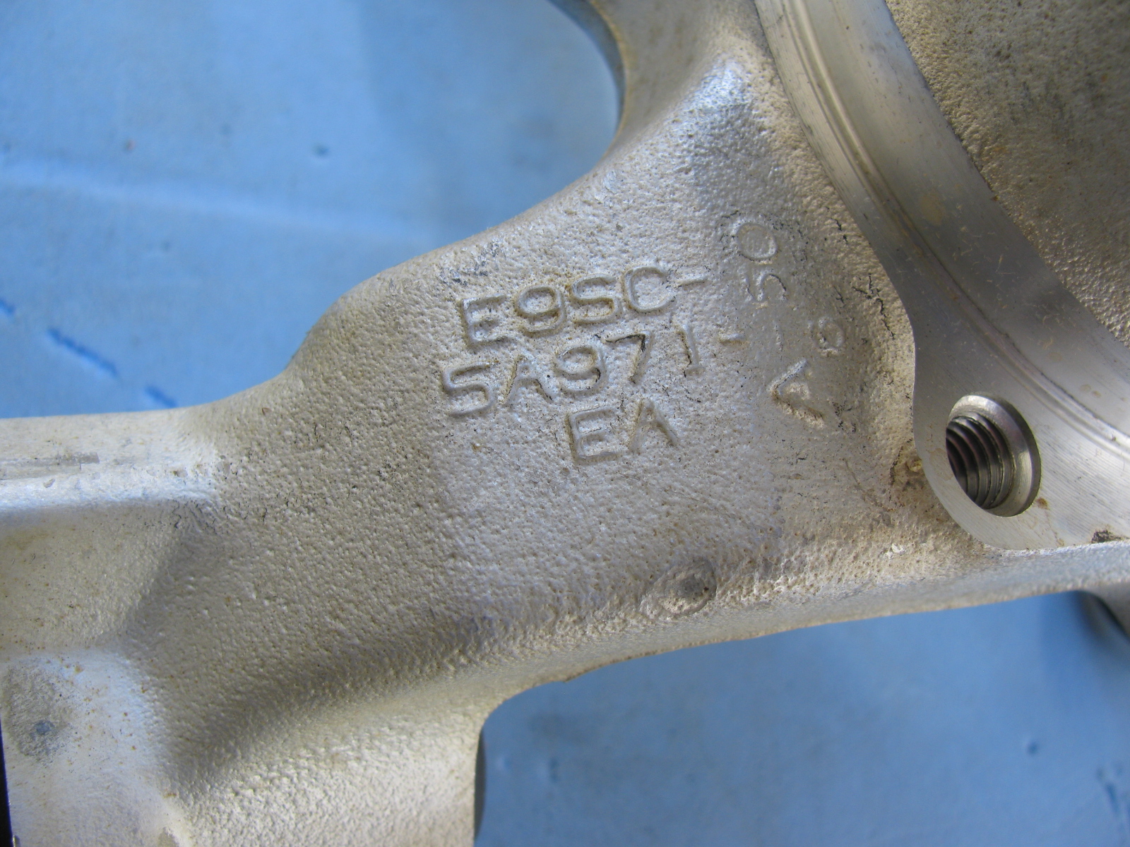
Here are some additional pictures of the IRS components and system . . . . “R” is for Right side of vehicle (passenger side in the US)
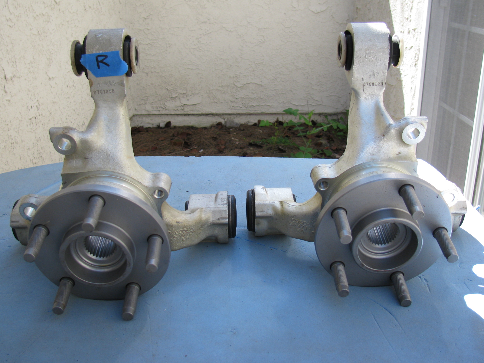


Above left: The IRS upper control arm has another pair of small mounting tabs that are not mentioned in the assembly manual. No pictures are included in the manual, either. After a quick search on the Factory Five forum, I found out the smaller set of tabs point downward, and are used for quad shocks – used to minimize wheel hop during acceleration.
Give Me a Brake – Again
Now, the rear brakes are another story. Seems the Factory sent me the wrong rear brake kit. So now I have to wait for the correct parts to arrive, and then have to send the wrong parts back. . . Stay tuned for more . . .
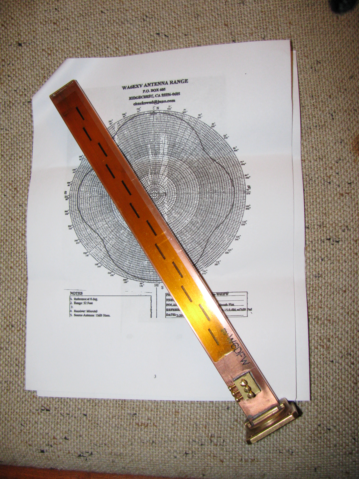
Another Box Arrived this Week – a 10 GHz Slot Antenna
I received this nicely machined antenna for 10 GHz earlier this week. It is made by fellow SBMS member Dan, W6DFW.
Here’s a picture of this omni-directional microwave antenna. The background is the radiation pattern plotted by another SBMS member, Chuck, WA6EXV.
I am planning on using this to make my roving 10 GHz station even more portable, perhaps getting on 10 GHz FM mobile. More on this item and possible applications at station KH6WZ later.
The San Bernardino Microwave Society (SBMS) had a Christmas party this past weekend, and it was a good break from doing sheet aluminum work. The event seemed smaller this year, several of the usual suspects were not able to make it. There was lots of food to share and gifts to exchange. Happily, regular guests Mel WA6JBD and his better half, Tisza KI6DBR came and brought their usual homemade treats, including Tisza’s famous chocolate truffles, microwave dish cookies and a chocolate sculpture. This year’s sculpture was a 10GHz horn and a section of waveguide. And yes, they really do work at 10GHz. Mel measured the return loss of the horn and waveguide and reports more than 17dB or something like that – pretty respectable for an edible 10GHz antenna.
Here are some pictures of the event. . .

Where else but a ham radio Christmas party would one find a 10GHz horn and waveguide made of chocolate – that actually works

Tisza’s homemade chocolate truffles – Yum!


Gift exchange crowd
What in the World is That?
After the party wound down, I stayed to get a closer look at Dennis’ new camera. It does not look anything like a camera, but it really shouldn’t because it makes images in a whole new way and enables a whole new way to enjoy still images. I thought it looked more like a kid’s kaleidoscope, rather than a camera.
The camera and lens system optics look very simple. And that is one of the points: You do not need fancy telephoto or macro lens capability. It is done in software. There are no fancy controls or buttons, only soft pads on the rubberized parts of the case. There is a power switch, a zoom control and a shutter release. An LCD with touch screen is on the back. Here are some pictures of this new gadget.

WHAT is THAT!

The Lytro camera. At left is the lens cover, it attaches magnetically. That’s an item that will be lost immediately. Center, the camera, showing the front glass and lens. Right – a tripod adaptor.
As I mentioned on my LinkedIn update, the Lytro camera introduces a paradigm shift in the way we can look at still pictures (pun intended, sorry). At first, I thought this camera simply used some sort of image processing to “fix” images, simple things like contrast and color adjustments and maybe some image manipulation, like PhotoShop. But then Dennis said that you can change focus and “raw image” features, like zooming in – after the image is stored on your computer.
The images are not jpg or other familiar formats – but then – these are not ordinary images, either. You can actually change the depth-of-field – change the point of view of the image.
Watching some of the demos on the Lytros website made me think of scenes from the TV show “CSI:” because you can see an image captured by the camera, and you can actually zoom and move around the various places on the image, and see what else the camera captured.
Visit the Lytro website, pictures and demos and details are worth closer examination. Unfortunately, I don’t have any Lytro images to share – yet.
The Coupe Goof
The day after the party, I went back to work on the Coupe. Something bothered me as I looked at the images and some postings of other builders. The driver’s side footbox and the front, where the pedal box mounts, looked different than mine. And I found another driver side footbox front panel in my box of aluminum parts. I looked at the part number of the “extra” footbox front (15312) on the packing slip, and noticed the description: “Driver Footbox Front Wall, Coupe Wilwood Pedals.”
Argh. Since I have the Complete Kit, it came with a Wilwood pedal box. Part of the confusion is the way Factory Five Racing packed the sheet aluminum – the major parts are held in place on the chassis and are shipped in place. This would be fine for the builders using a donor Mustang pedal box, the “Basic Kit” version.
So, I had to remove the driver side footbox front panel and replace it with the proper one. The good news is that I had all these things in place with Cleco fasteners, not rivets and silicone. And, I used the old panel as a drilling guide for the new panel. Now I have a spare sheet of aluminum I can use for – something. Hatch covers, maybe.

On the left is the wrong driver side footbox front panel. This is the one that is shipped in place on the chassis. The one on the right is the front panel for the Wilwood pedal box. Good thing I didn’t silicone and rivet that panel!

Disaster averted – the wrong footbox front panel was removed and replaced with the correct front panel for the Wilwood pedal box.
