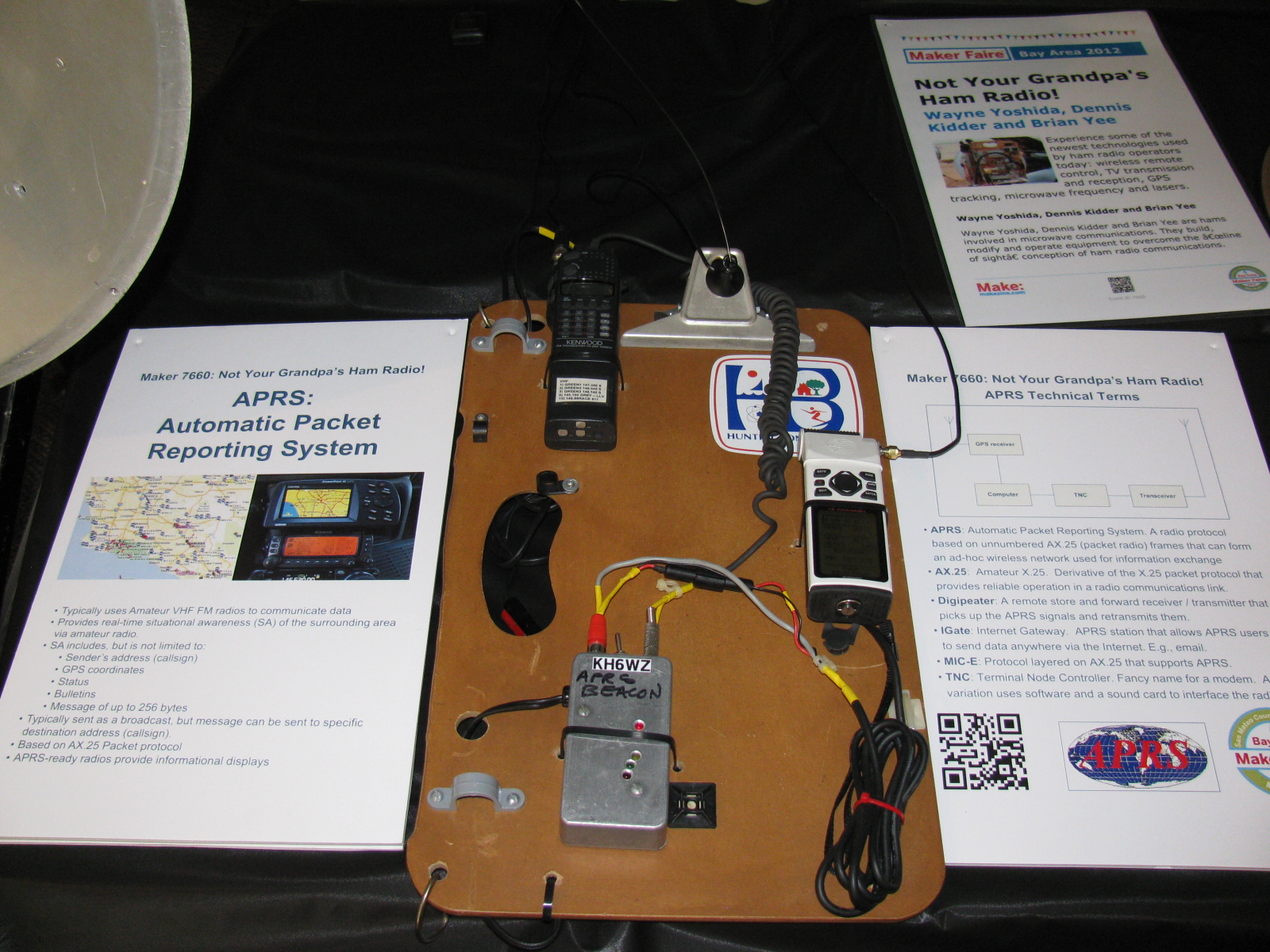
KH6WZ APRS Unit Two (KH6WZ-5)
My “high power” version of the tracker box is complete. This unit is housed in an aluminum instrument case, and uses a mobile radio (Radio Shack HTX-252) with 10W and 25W capability for remote locations. The GPS unit is an old Garmin Street Pilot Color Map.
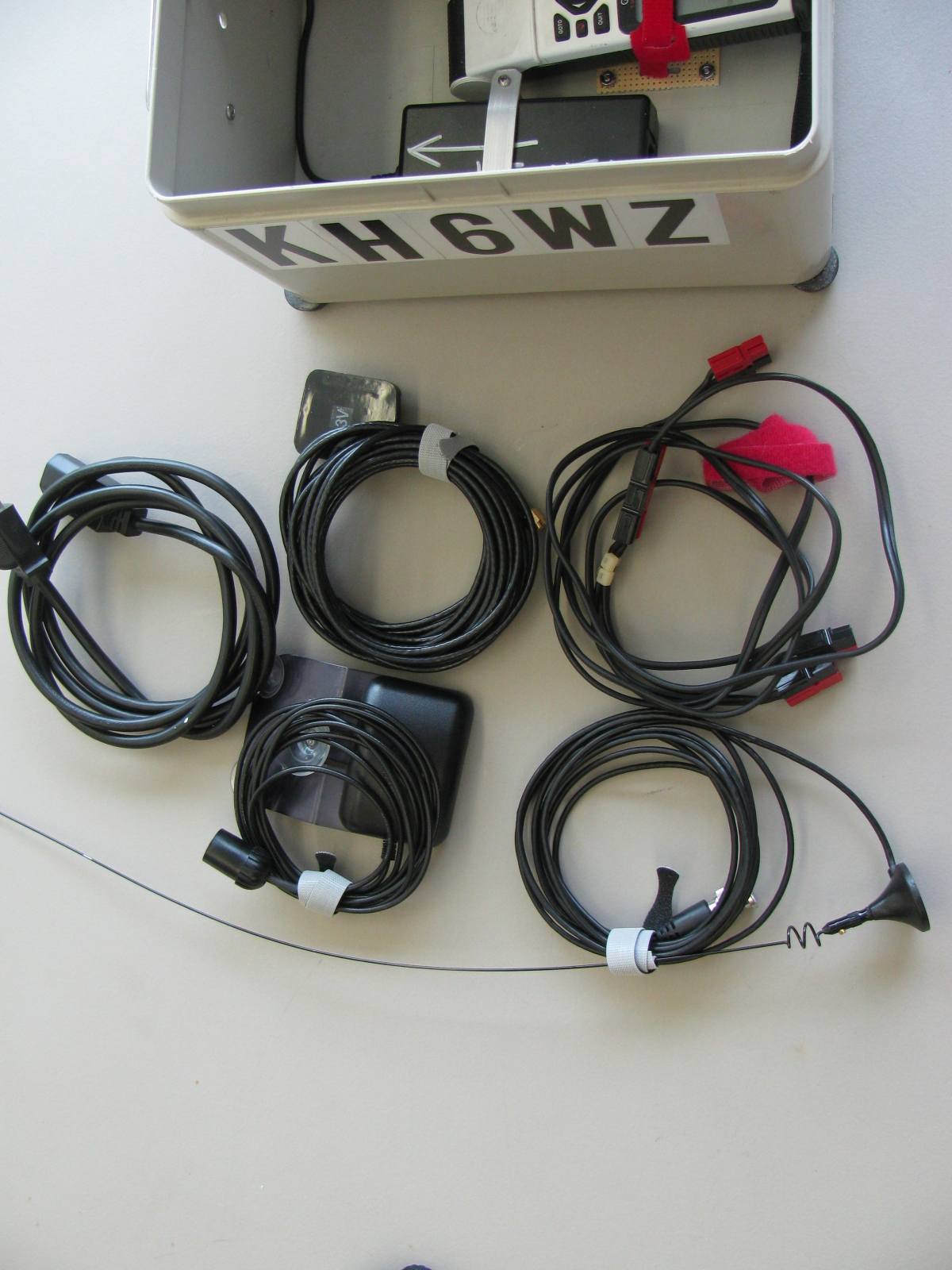
The bottom of the box (on the left) is used to store cables, the original microphone in case I need to use it as a “radio,” a GPS and a two meter whip antenna. A gel-cell would fit nicely in this space for “truly portable” operation.


After Field Day and the demonstration at the Discovery Science Center in Santa Ana, CA last month, I decided to add information on my TinyTrak APRS units on this site.

I re-packaged the unit to simplify deployment and to make it more practical for a “grab and go” event. On the left is a two meter (144MHz) hand-held radio, with the battery pack removed, and powered by external 12V via the DC IN jack. The TinyTrak 2 is next to the HT, in a die cast aluminum case (Hammond 1590B). On the bottom of the box is an old Garmin GPS 45XL and a 12V wall-wart type AC power supply. The bottom of the box also stores a magnet mount antenna for radio, an external GPS antenna and a DC power cable. There’s plenty of room for a gel-cell.


Under Construction
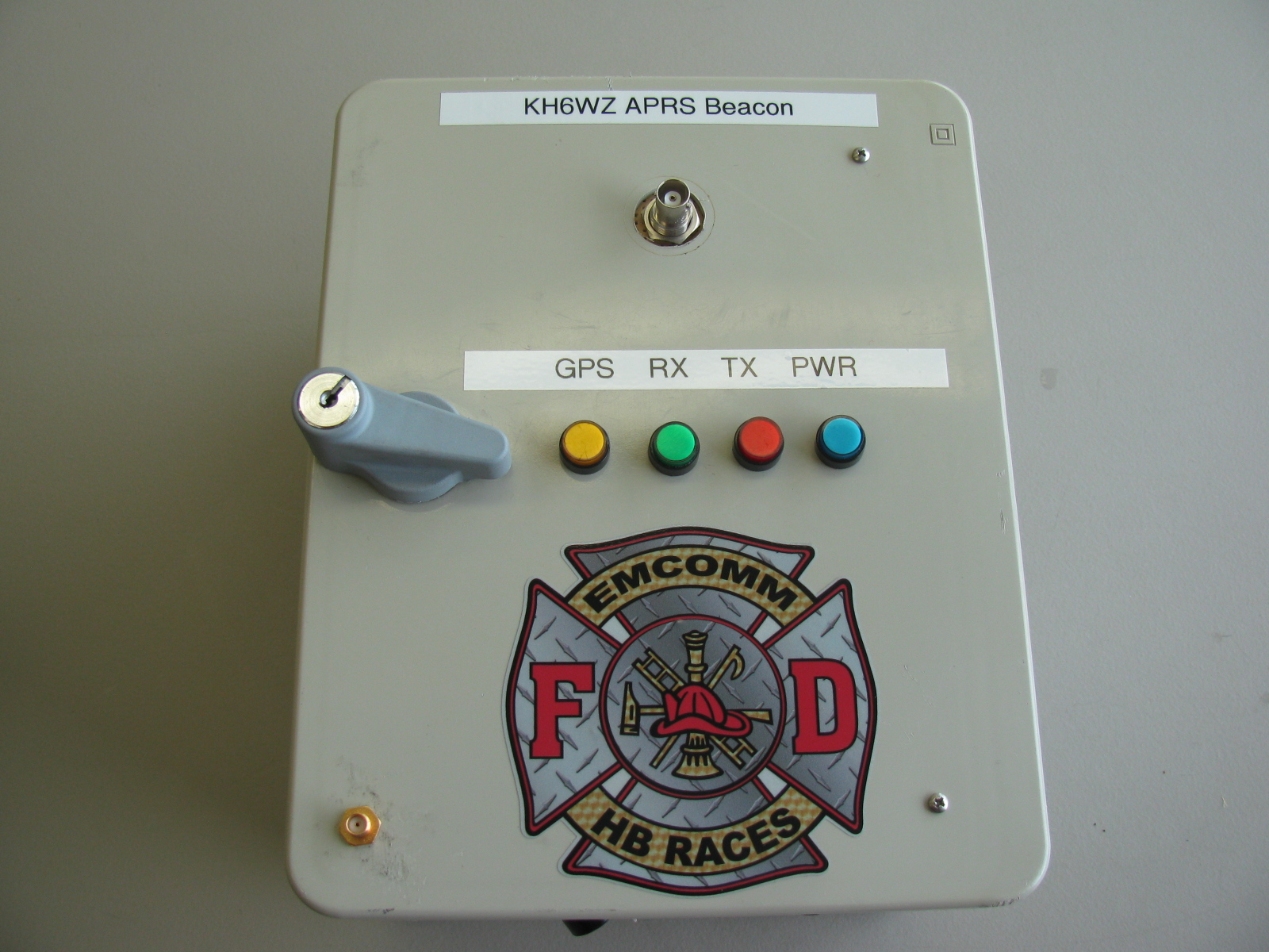
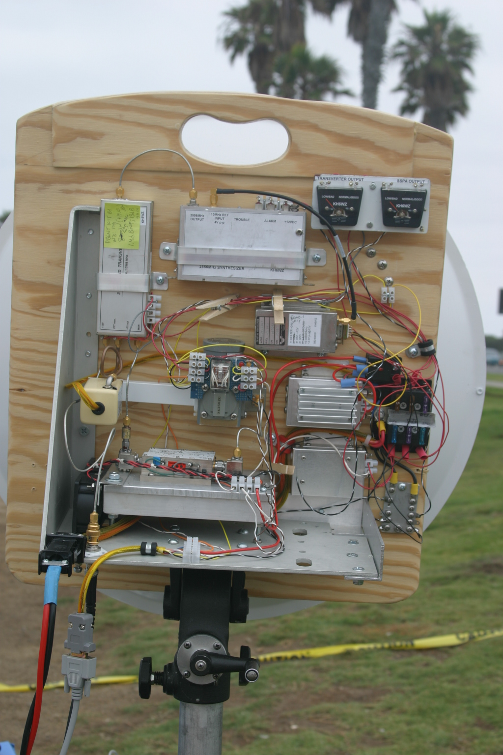
After completing the HB RACES KH6WZ APRS Beacon above, I decided to do a similar thing for my old Garmin Street Pilot. In this version, the GPS unit will be mounted on the outside of the cabinet so the map display will be visible. An inexpensive Radio Shack HTX-252 two meter mobile rig (bought new on a close-out sale years ago) is mounted to the top panel. This unit will be capable of high power operation (10 Watts low power, 25 Watts on high power) to get the signals out in fringe areas. Here are some pictures of the unit under construction. The aluminum chassis box is a surplus instrument case. It is nice and rugged, with a handle on the top.
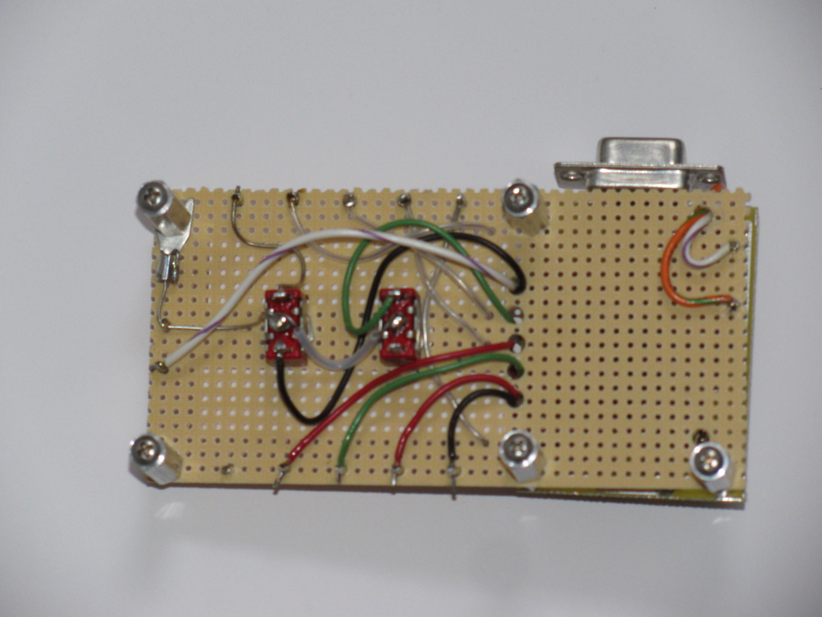
Here you can see the mobile rig at the top left, a row of LEDs to indicate APRS status, the TinyTrak unit and a small perf board with RCA jacks for the GPS signals coming out of the Street Pilot.

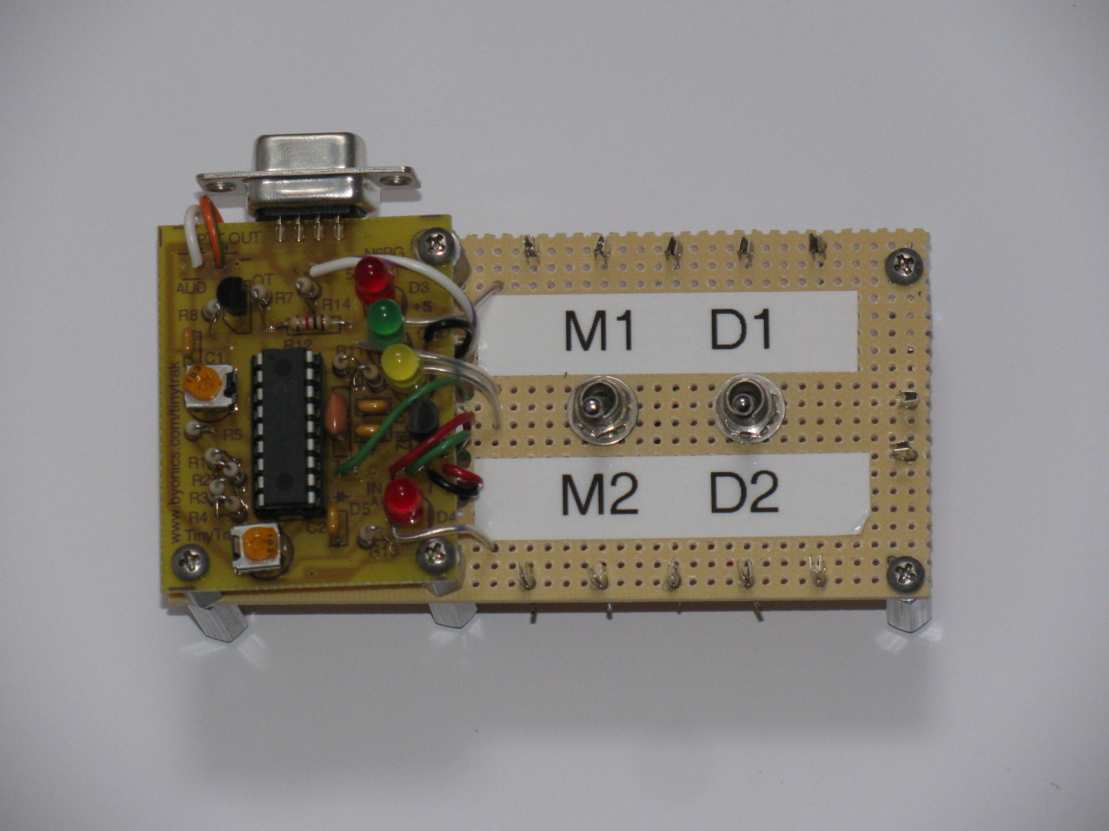
Here is a close-up of the TinyTrak PCB and a break-out board for the unit. Switch M1/M2 selects the primary or secondary message programmed in the TinyTrak; switch D1/D2 selects internal display (D1) or the external display (D2). More details on these functions appear below in “One Way to APRS Beaconing.”

Here is a bottom view of the TinyTrak motherboard…. Mounting the TinyTrak this way will help preserve the PCB trace pads and should help simplify access to the wiring when and if it needs repair.

The following information is based on my original article called “Where in the World – A Look at APRS” in the CQ Magazine Beginner’s Corner for November 2003. Click here to see the table of contents of this issue.
I’ve always been fascinated by those “tracker systems” used in the movies and television. You know, like the scene in the movie “Armageddon,” where the ground controllers are watching each member of the “A” and “B” Shuttle teams. Or the “homer” made by “Q” in the James Bond movie “Goldfinger.” I found an expensive and fake homer here, but it is just a fancy sound maker with an LED – take a look at this thing. . .
Today, and in the real world, hams have access to this interesting technology: It’s called the automatic position reporting system (APRS), developed by Bob Bruninga, WB4APR. Basically, it uses latitude and longitude information from the global positioning system (GPS) satellites and transfers the data via packet radio on 2 meters. Mix an APRS station with the Internet, and we have a system in which hams can keep track of moving objects remotely. Interfaced with a suitable weather station, local “micro-weather reports” can be viewed. If you know anyone into APRS, take a look at the N1BQ Web site and plug in their callsign into the search field. You’ll be able to see what he or she has been up to (or at least where they went) lately.
Several members in the local radio amateur civil emergency service (RACES) group made “tracker boxes” and use them for special events, like the Baker-to-Vegas Challenge Cup Relay race. When I saw their APRS systems for the first time, I thought, “Hey, that’s really neat.” Then I went, “Hmmm. What would I do with such a thing?”
Like a lot of hi-tech gadgets, if you think hard enough, you will come up with a lot of reasons to build, buy or otherwise own one. Here are some examples of what you can do with an APRS tracker box:
- When interfaced with a compatible weather station, the APRS beacon can also transmit weather information
- If you are involved with a public service group, you can watch where a person or vehicle is in near real time
- You can re-trace and display your driving, sailing or boating routes via the Internet, and friends and relatives can watch, too
- Put that working but old and un-used 2M HT or mobile radio to good use
Remember that an APRS unit is an Amateur Radio beacon, and must comply with FCC Rules on Beacons, One Way Transmissions, Station Identification and Stations Under Remote Control.
In order to have a moving APRS station, you will need a 2 meter station (rig, antenna, power source), a terminal node controller (TNC) with APRS capability, a computer and a GPS unit. If you are doing packet radio now, or have some packet gear in the closet someplace, you are already more than half way there. By the same token, if you enjoy boating or camping, you may already have a GPS unit.
2013 UPDATE: Many VHF mobile rigs – and some HTs too – come with an APRS capability either built-in or have this feature available as an internal option. This is pretty amazing and shows how fast technology can change.
Here are some notes about what you need to make a simple APRS beacon.
The GPS Receiver and Antenna
The GPS unit does not have to be new – and, in fact, older units might actually be better, since the newer units have gone to the small MCX and other exotic connectors, rather than the easy to use and adapt BNC or SMA connector. I use an old Garmin GPS 45XL and a Street Pilot Color Map, both units have been discontinued many years ago.
Almost any GPS receiver can be used for APRS, but a critical feature the GPS unit must have is a connector port for serial data output in the National Marine Electronics Association (NMEA) format. Just about all “camping” and “marine” GPS units have this data interface.
I suggest looking for the following features, in this order of importance:
1) Ability to access the GPS data output via a serial port. Check to see if the data interface cable is available, or can be easily made or modified. See an interesting alternative source for Garmin-compatible accessory plugs in the Reference section.
2) Ability to use an external antenna. In essence, all GPS units are radio receivers, and, just like your radios, require a good antenna for the best performance.
I have found amplified GPS antennas on eBay and other places for as little as $20. Some GPS modules include a patch type antenna built-in. This may or may not be optimum for use in the field, but today’s GPS units have much more channels than the 10-plus year old units I am using for my system.
3) Ability to apply external 12VDC power. Small penlite cells can get expensive after a while, so the ability to plug into an alternative power source would be good. Be aware that some units need a power source lower than 12V to 15V, and can be damaged if 12V is applied directly to the unit. But do not fret, if your GPS unit needs something other than 12V, you can build or buy a suitable voltage converter to handle this. The simplest way to use external power is to see if the unit has a cigarette lighter accessory or some other external DC cable, and use that. For non-automotive use (like pedestrian mobile), you can remove the cigarette lighter plug and use a gel-cell or other 12V power source.
Garmin seems to be the most popular GPS units for APRS. I think their excellent customer service contributes to this, based on personal experience.
Full-featured GPS units might be a bit extravagant for just APRS applications, so if you are not into flying, backpacking, sailing or other activities requiring navigation, you might want to consider a GPS “module,” rather than a GPS “receiver.” The GPS module is just a “plain data receiver box” with no display, and is intended for use with some other gadget, such as a computer. Because no other “support electronics” is involved, prices for GPS modules are much cheaper than GPS navigation units.
The Interface and the Rest of the Components
An APRS interface is the “brain” that transfers the digital location data from the satellites and instructs the radio transceiver when to transmit and when to receive. More sophisticated units can interpret more GPS information, and transmit more than simple latitude and longitude. For example, on a moving vehicle, the APRS unit can send not only position, but also speed, rate of climb or rate and direction of turn, altitude, a station identifier and an icon.
There are dozens of different symbols used in APRS to indicate what sort of object is being tracked. For example, my friend Peter Barbour, N6RAS, is an avid sailor, and uses a boat icon when he is “beaconing.” Bill Honeyman, KG6CNL, uses a jeep, and Steve Graboff, W6GOS uses a “running man” symbol during the Baker to Vegas race. The eye icon was used during the demonstration at the Discovery Science Center, see the screen capture below.

One Way to APRS Beaconing
There is a simple way to try APRS. The TinyTrak unit, by Byon Garrabrant, N6BG, is a wonderful little circuit that eliminates the packet TNC. If you have a “TT,” all you need is a GPS receiver, a two-meter radio, antennas for the GPS and radio and a power source. The unit is configured via the serial port in your personal computer.
Now in its fourth generation, the TinyTrak units are available in a “fully-assembled” version, complete with a small 2 meter transceiver. The older generation small PC board versions of the TinyTrak are still available.
My units vary somewhat from the “out-of-the-book” instructions. I added an SPDT, center-off toggle switch to make a “test” function: In the test mode, the unit is powered up normally, and the LEDs blink to verify operation. After checking the blinking lights and verifying the two meter rig transmits data, the switch is thrown into the “operate” mode, which simply cuts off the ground connection to the LEDs (making them go off) to conserve battery power.
I recently added another modification: I added another SPDT switch (not center-off) so I can select either the small internal LEDs or the large front panel mounted LEDs when the unit is in operation. This is done to create a “light show” to attract attention during demonstrations.
Remember that the TinyTrak is a simplified beacon device. It will not receive and decode APRS data for display purposes. It is the “data transmitter beacon” or “homer” part of an APRS set up, but they are fun nonetheless.
Once you get your APRS beacon going, I am sure you will want to do more. In the meantime, the simple starter system will enable you to beacon your position while you do your favorite radio-activity, from public service to outdoor events. James Bond’s homer technology is here for hams, and is an exciting and interesting bit of technology we can use just for kicks or for serious public service assistance.
Links to More Information
General APRS info
http://web.usna.navy.mil/~bruninga/aprs.html
http://www.aprs.net
http://www.tapr.org
APRS Symbols
http://www.aprs.net/vm/DOS/SYMBOLS.HTM
See Beacon Locations on the Internet
http://www.wulfden.org/APRSQuery.shtml
TinyTrak “TNC-less” APRS kits
http://www.byonics.com
Carter, Jim WB6HAG, “Build an APRS Encoder Tracker,” QST, February, 2002, page 28
GPS Modules
http://www.makershed.com/default.asp
An Interesting Connector Source for Garmin GPS Units
http://pfranc.com
Baker to Vegas Challenge Cup Relay
http://www.bakervegas.com

I have a house guest this week: a guinea pig. It’s been hot here so I placed an ice pack wrapped in a towel to help keep her comfortable. A guinea pigs’ safe operating area is between 65 to 75 degrees F (18 to 24 degrees C) since they cannot sweat. . .
Here are some links to hot weather guinea pig care:
http://guinea-pigs.livejournal.com/2577239.html
http://www.wikihow.com/Keep-Your-Guinea-Pig-Cool-in-Hot-Weather
National Public Radio (NPR) posted a story on eating guinea pigs….
http://www.npr.org/blogs/thesalt/2013/03/12/174105739/from-pets-to-plates-why-more-people-are-eating-guinea-pigs
The ARRL 10GHz and Up contests are coming up soon (August 17 to 18 and September 21 to 22), so I thought I’d re-publish my article that originally appeared in The Proceedings of Microwave Update 2005.
The Harris-Farinon Model SD-108175 / 076-108687-001 solid state power amplifier (SSPA) has been seen globally on the surplus market over the last few years. This amplifier is a part of a large rack of equipment running on the traditional 24VDC, positive ground telecom power system bus.
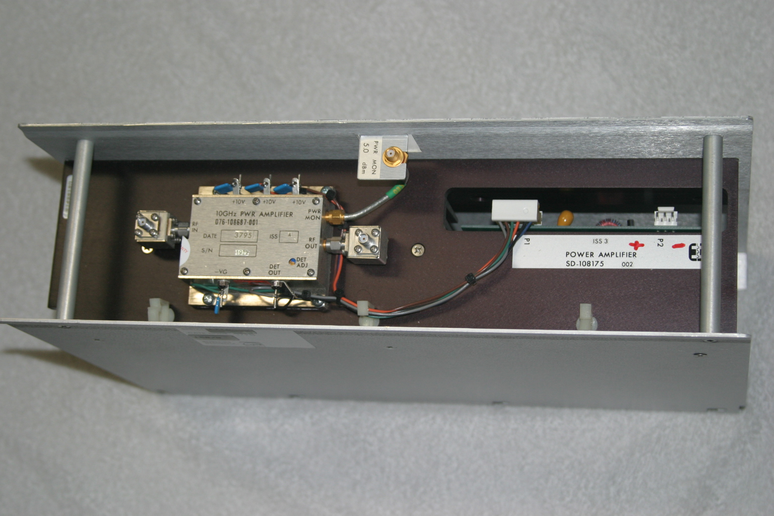
In its original form, the amplifier is very robust and heavy, since it is rated for continuous duty, Class A operation. Figure 1 shows the unit as received. It is mostly heatsink, and the RF unit, where the microwaves are amplified, is the tiny silver box on top.
The SSPA unit (Model SD-108175) measures about 15-1/2 inches wide, 4-1/4 inches high and 10 inches deep, and weighs over 15 pounds. The little silver box (part number 076-108687-001) with SMA isolators at the input and output, is about 3 inches wide, 1 inch high and 2-1/2 inches deep.
Important: Be careful if you see these units for sale, I have seen some inaccurate descriptions of these units – for ham radio use, the only item we want is just the amplifier (076-108687-001) and not the heatsink/chassis assembly or the power supply DC-DC converter.

Figure 1. The Harris-Farinon 10GHz amplifier is very beefy, but it is mostly heatsink. The little silver box is where the RF is amplified.
I took the unit to Dave Glawson’s lab (WA6CGR) to see if we could integrate this SSPA into my X-band rig. It is a 1W unit, but I have several that put out as much as 3W on 10368 MHz. I purchased several of these units at a very reasonable price, and am pleased with their performance on the 10 GHz Amateur Radio band.
The terminals on the amplifier as well as the power supply PCB are marked, simplifying some of the guesswork about what-goes-where. The amplifier includes a “POWER MON” SMA female jack, which should probably be capped with a 50Ohm termination to prevent oscillations or weird things from happening while the amplifier is operating. A “DET OUT” pin is useful to verify amplifier operation.
It may be prudent to read Chuck Houghton’s article, “Above and Beyond, Microwave Stripline Retuning Procedures” on tweaking circuits before any “poking around” is done on any SHF amplifier, to prevent damage. Links to references are at the end of this article.
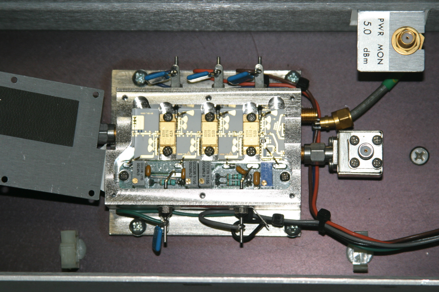
The first step is to power it up and verify operation in its “as-is” state. With about +17dBm (about 60mW) input, power output is about +35dBm, or a little over 3W at 10368MHz. Current consumption is about 2.6A during standby and about 3A at 10V with RF applied. Dave and I wondered whether or not we could tweak the amplifier to get more power out, so we took a look under the lid of the little silver box, see Figure 2. We decided not to tweak anything inside the tiny box.

Figure 2. A peek inside the SSPA. No tuning is required to get two to three watts output on 10368MHz.
Since the amplifier passed its first tests, the next step is to re-package the unit so it would be more suitable for portable and roving operations. Certainly, a weight reduction could be done by shrinking the size of the RF module heatsink, and adding a fan or two.
Since the amplifier passed its first tests, the next step is to re-package the unit so it would be more suitable for portable and roving operations. Certainly, a weight reduction could be done by shrinking the size of the RF module heatsink, and adding a fan or two.
The DC-DC Converter
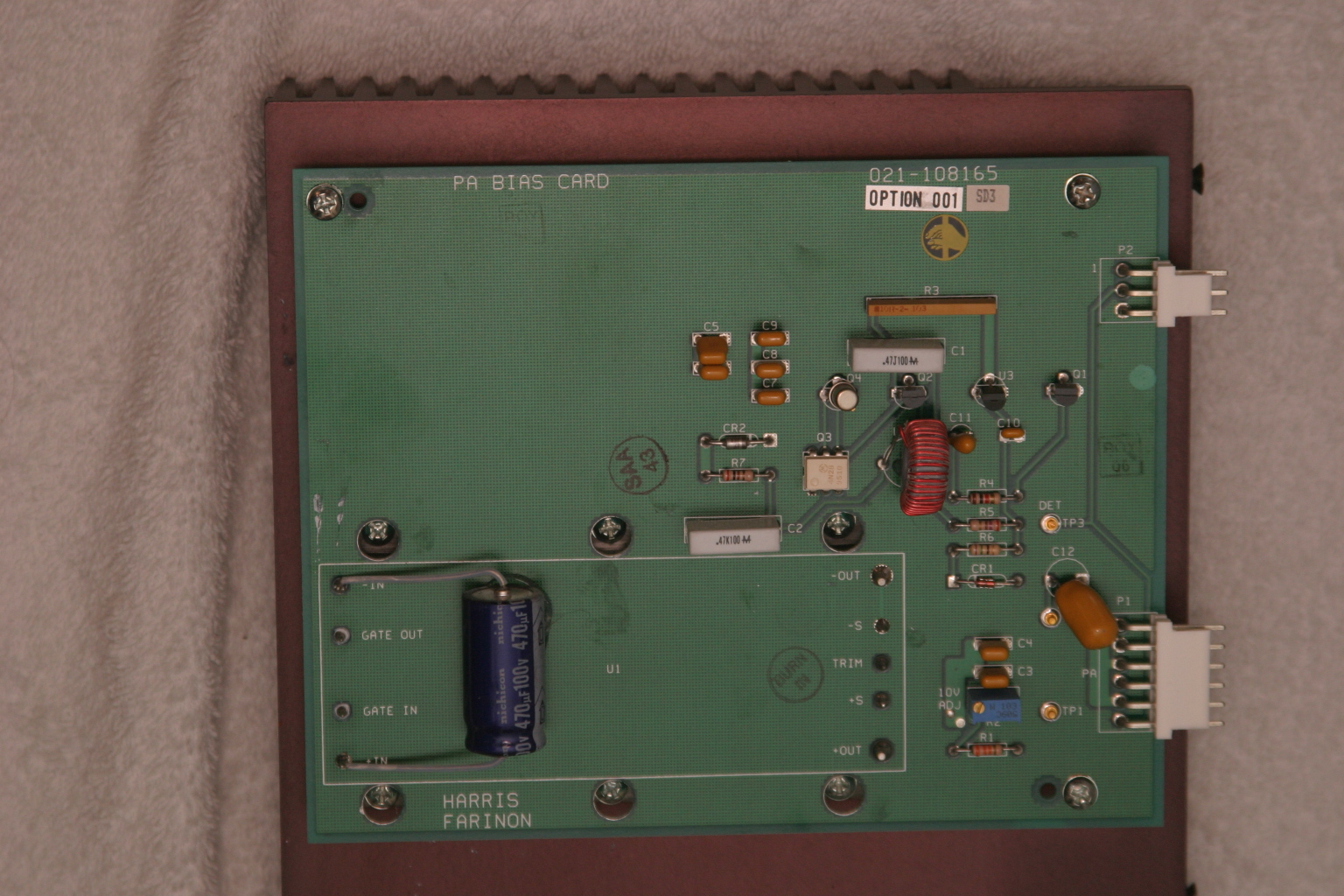
The original power supply board appears in Figure 3. A casual inspection of the unit showed that the 24V input was buck-regulated down to 12V, and then further reduced to minus 2.1V for the bias and +10V for each stage in the amplifier. The DC-DC power supply looks like it can be modified and re-used, by applying 12VDC where the brick converter has its output. However, this modification was not attempted.

Figure 3. The DC-DC supply board. A 24V to 12V brick converter is mounted to a 14-1/4 inch by 7-1/4 inch heatsink under the PCB. The existing DC-DC converter may possibly be modified to make the unit work on 12VDC input. See text.
I thought a better, lighter, more modern power supply could be built fairly easily, and the large heatsink for the power supply could be deleted.
With Dave’s help, I made a simple DC-DC converter using a Linear Technology LT-1083 adjustable regulator and a few resistors for the +10V supply. The negative bias supply was made from a surplus 99-cent DC-DC converter. I built the power converters into separate chassis boxes, since I had them on-hand. A single box is also acceptable.
Like all FET power amplifiers, one must make sure that the minus (gate) bias supply is always connected before the supply voltage to prevent damage to the devices. I am sure there are several solutions for power-on sequencing to prevent this from happening, including relay or other switching or timing schemes. However, I chose a very simple route: I simply wired the minus voltage directly to the amplifier bias feed-thru capacitor, with no switching in-between. The plus 10V supply line is switched to the amplifier via a power relay, actuated by the sequencer. This way, whenever the rig is powered up, the minus bias voltage is “automatically” applied (it was never off in the first place), and the plus 10V is applied only when the rig is put into transmit mode.
I had a pair of 24V brushless DC motor fans in the junk box, so I am using these to blow on the heatsink. Since I have both 24V and 12V running around in my rig, I wired up a two-speed fan control using a pair of spare relay contacts. When the radio is in the receive mode, 12V is applied to the fans, reducing the noise. When the rig goes into transmit mode, 24V is applied to the fans, running them at full speed.
The final result is shown below. The amplifier is mounted in one of my 10GHz rigs, “Ms. June.” 3 The SSPA puts out 2W at the antenna port, and now measures about 4 inches by 7 inches by 1-1/2 inches, including the cooling fans. A re-labeled, surplus CB panel meter (1mA movement) connected to the DET OUT pin indicates SSPA operation. (Update: Ms. June was cannibalized for parts. However, many of her parts were used in other radios, including my latest, record-setting 10GHz transverter.)

Figure 4. The Farinon SSPA installed in “Ms. June,” one of my early 10GHz rigs. Two watts appears at the waveguide port at the antenna relay in transmit. The DC-DC converters are enclosed in separate chassis boxes, and can be seen just to the right of the amplifier. A re-labeled surplus meter monitors amplifier operation.
References
1 – “Above and Beyond, Microwave Stripline Retuning Procedures,” by C. L. Houghton, WB6IGP, San Diego Microwave Group:
http://www.nitehawk.com/rasmit/mstrp_tu.html
2 – The surplus TDK DC-DC converter is described as a “5V in +/-5V DC/DC converter” at MPJA Online, as part number 1042518. This unit is under a “closeout” deal, so supplies may be limited. Go to http://www.mpja.com, and look under “Power Supplies,” “DC-DC Converters.” Their phone number is 800-652-6733, 9AM to 5PM Eastern Time, Monday through Friday. Although probably not necessary, I removed the TO-220 device from the board and re-mounted it to the metal chassis box for heat-sinking.
3 – Most of the SBMS members have names for their rigs, mainly because, as many of you know, microwave radios tend to have personalities of their own. Ms. June is my sixth 10GHz radio re-build. “Morpheus” was my first attempt, see CQ magazine for December 2003 and January 2004 for my dubious start on the microwave bands.
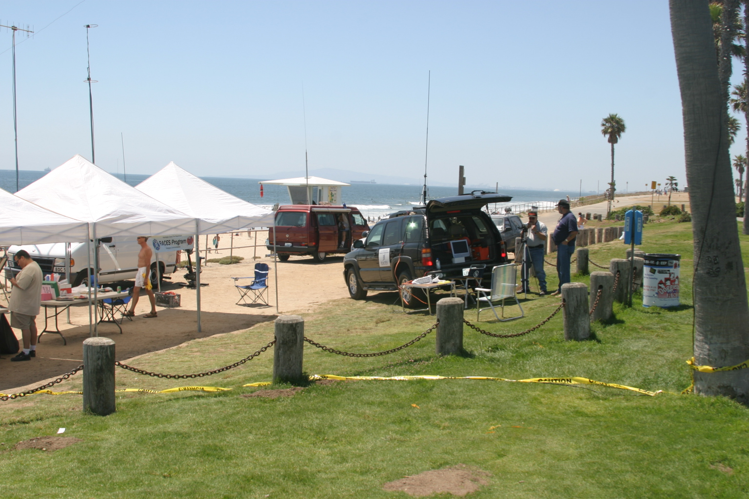
Field Day weekend 2013 is now history. Our new location helped to further increase visibility from both Pacific Coast Highway (PCH) and the bike path along the beach.
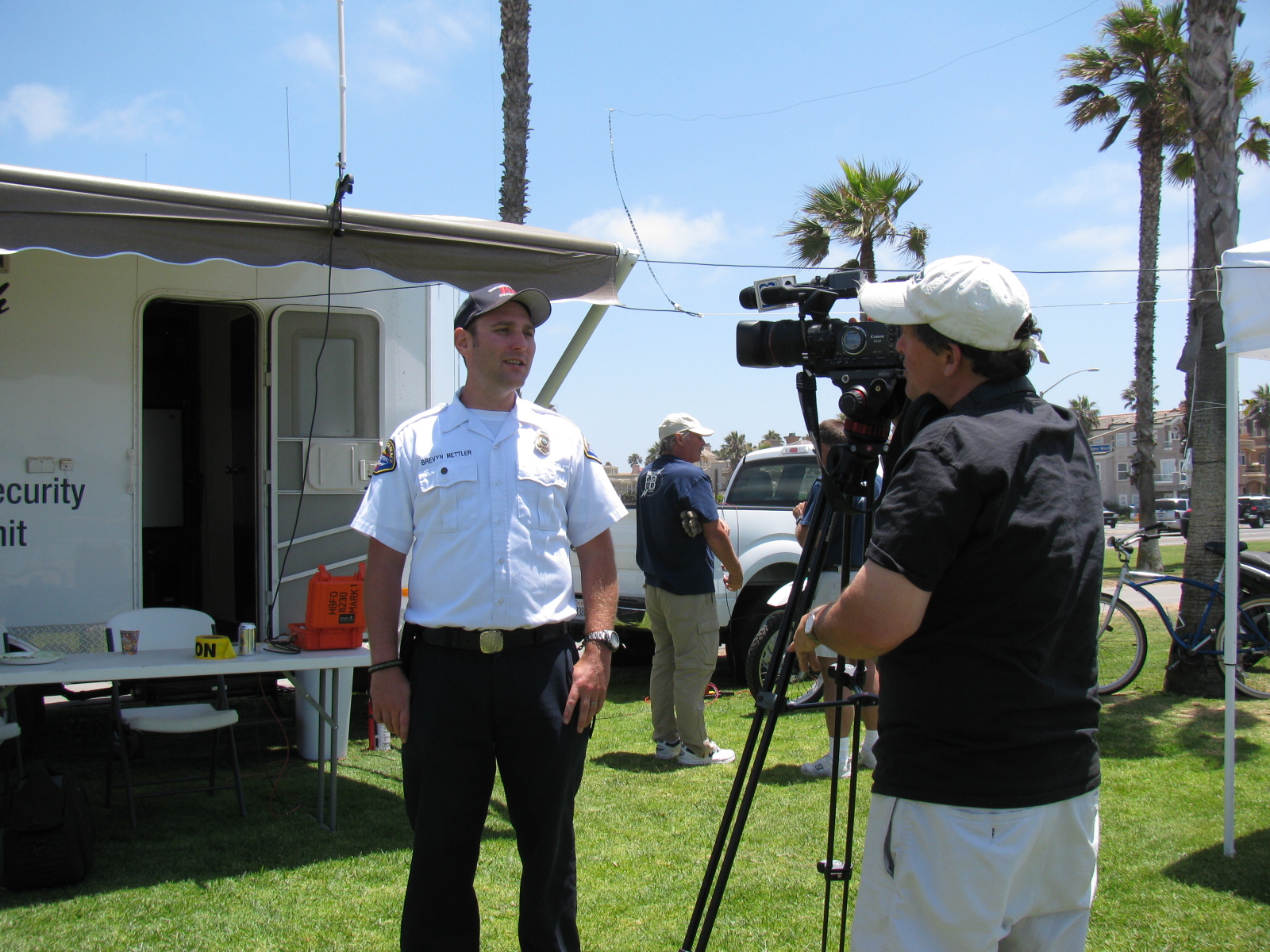
This year, we had many more visitors – Fire Department management, local dignitaries, licensed hams, ex-hams and ordinary people. Our local cable TV channel (HBTV-3) shot lots of video of our operation. There were several minutes of live video from the Huntington Beach Police helicopter via amateur television (ATV).
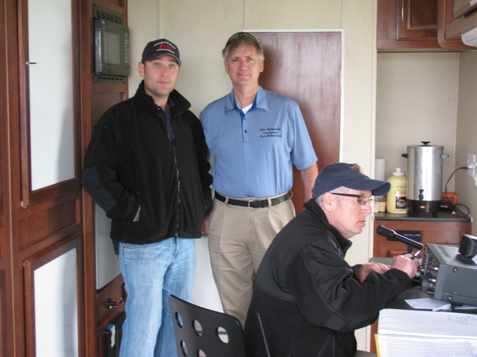
Below: Huntington Beach Emergency Manager Brevyn Mettler, KI6FRG (left) and Huntington Beach Council Member Jim Katapodis, discuss the Field Day layout and the objectives of the Field Day drill as HB RACES Chief Radio Officer Dr Steve Graboff, W6GOS makes 20 meter SSB contacts.

Al KJ6RIX and Jennifer did an amazingly great job keeping all of us well fed and even sheltered – a huge thanks for their hospitality!
Sometime in the late evening, Tim WD6AWP succeeded in getting a 2-way contact via satellite (OSCAR – Orbiting Satellite Carrying Amateur Radio) – this is a first for HB RACES – way to go, Tim!
Huntington Beach RACES looks forward to another Field Day next year, hopefully with an improved score and even more participation.
Some videos are posted on my YouTube Channel, KH6WZ
Part 1 of 3
Part 2 of 3
Part 3 of 3
Highlights – City of Huntington Beach RACES Field Day Visitors
Jim Katapodis, Huntington Beach Council Member
Fred Wilson, Huntington Beach City Manager
The guys from Station 46: Bob, Brian, Keith, Mike
Here are some random pictures from the weekend. . .
Below: Robert Thompson, KE6RKG, making contacts at the VHF-UHF station at the W6O Field Day operation in Huntington Beach, Calif.

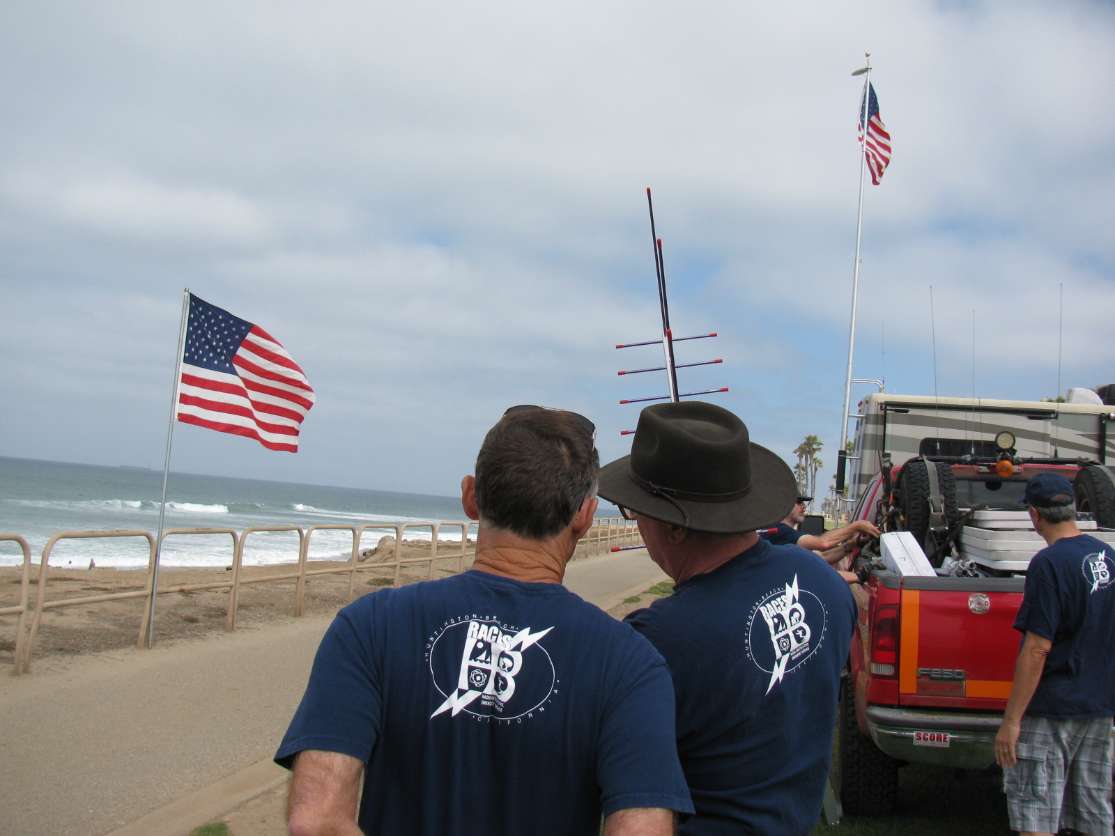
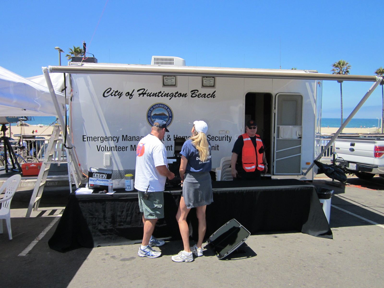
Below: A view of the trailer and the open grassy area just before antenna installation.

Below: Pete Zilliox, K5PZ working the keyer on 40 meters.

Below: Brevyn getting 15 minutes of fame on HBTV-3, the Huntington Beach cable TV channel.

Below: Tim Sawyer, WD6AWP (left) and Pete Zilliox, K5PZ (right), scanning the sky for an Orbiting Satellite Carrying Amateur Radio (OSCAR) contact. Tim successfully completed a two-way contact via satellite late Saturday evening.

Below: Brevyn, KI6FRG, making some contacts on 15 meter phone.

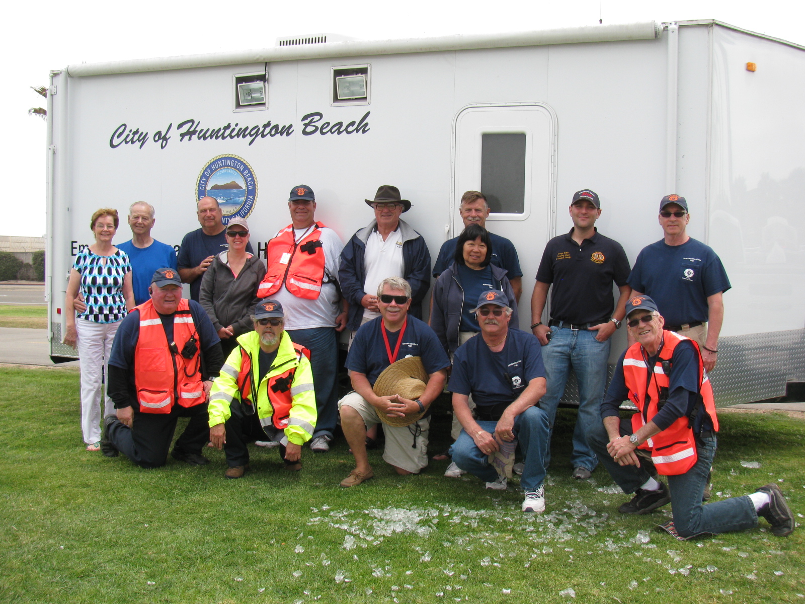
Below: The HB RACES Field Day group, 2013: 4A Orange.

City of Huntington Beach RACES Field Day Participants
K5PZ Pete
K6DAA Gordon
KA6HMS Bill
KB6JOE Joe
KB6PAL David
KC6ZOW Shelley
KE6BNS Jeff
KE6OCE Steve
KE6RKG Robert
KE6WUO Michael
KG6IQL Manny
KG6SKD Marshall
KG6ZDP Jim
KH6FL Marilyn
KH6WZ Wayne
KI6FME Mike
KI6FRG Brevyn
KJ6RIX Al
Jennifer
KK6ANY Gus
N6PBW Ginny
N6RAS Peter
N6SLD Roy
N6YDX Darrell
N9KVN Steve
WD6AWP Tim
More images are posted on the City of Huntington Beach RACES website
73,
Wayne KH6WZ
Huntington Beach RACES Public Information Officer


HUNTINGTON BEACH, Calif. — On Saturday, June 22, 2013, from approximately 11 AM near the intersection of Pacific Coast Highway and Goldenwest, a team of Huntington Beach Radio Amateur Civil Emergency Service (RACES) communications volunteers will demonstrate and practice their emergency radio communications skills in a nation-wide drill called “Field Day.” The goal of the drill is to contact as many other similar stations around the nation as possible in a 24 hour period.
During an emergency, normal lines of communication, including landline and wireless telephone systems, often become over-loaded. Ham radio volunteer groups such as RACES teams, step up to fill these communications gaps during a crisis.
Steve Graboff, MD, HB RACES Chief Radio Officer, said, “The HB RACES team participates in this national exercise every summer to make sure we are ready for an emergency, such as an earthquake, fire or flood.
“We use our personal equipment and volunteer our time to provide this service at no cost to the City. In addition to Field Day, we provide our radio communication skills to support public events such as the Surf City Marathon and the Independence Day parade and public safety events such as the National Weather Service weather spotter program,” Dr. Graboff added.
The public and the news media are invited to observe and even participate in the emergency communications exercise.
About City of Huntington Beach Radio Amateur Civil Emergency Service (RACES)
The Huntington Beach Fire Department Emergency Management and Homeland Security Office administers the RACES team. RACES (pronounced “RAY-sees”) is not a club, it is a volunteer group within a government agency. There are 18 city RACES groups within Orange County, operated under their respective city and county emergency management departments. To learn more about HB RACES, go to http://www.hbraces.org

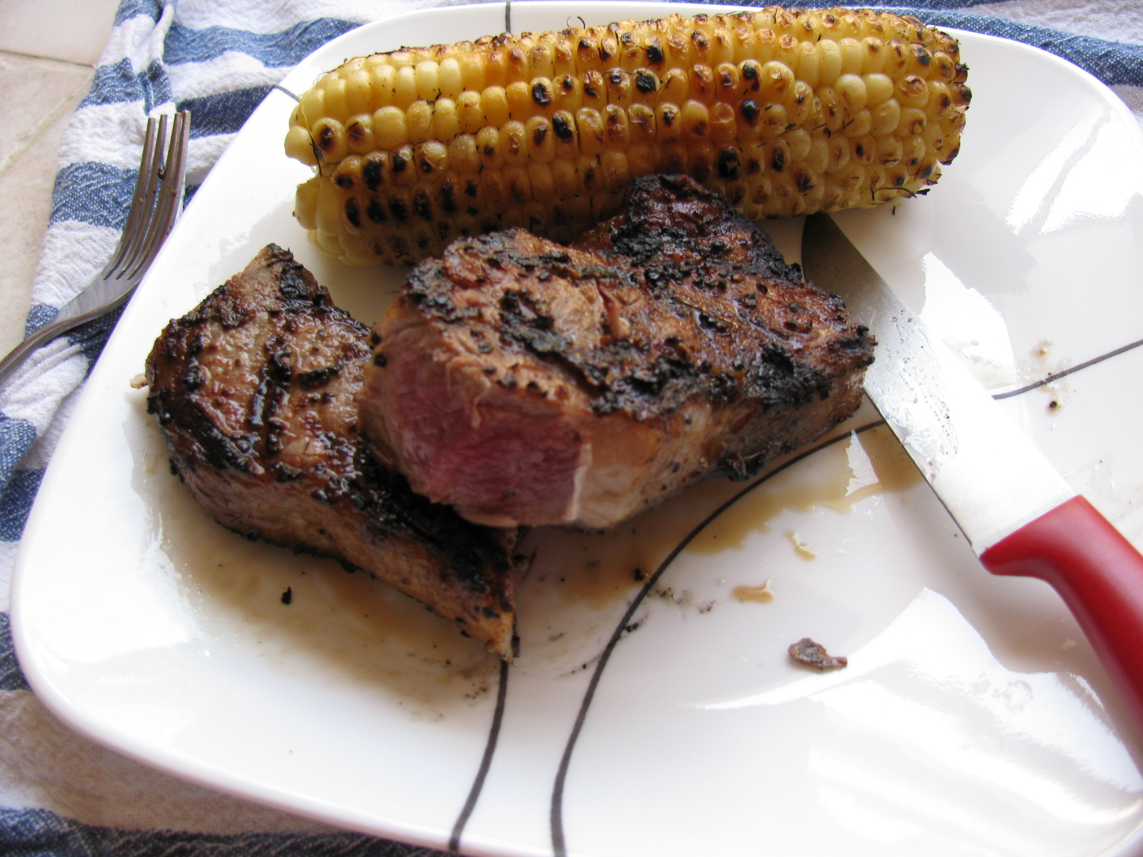
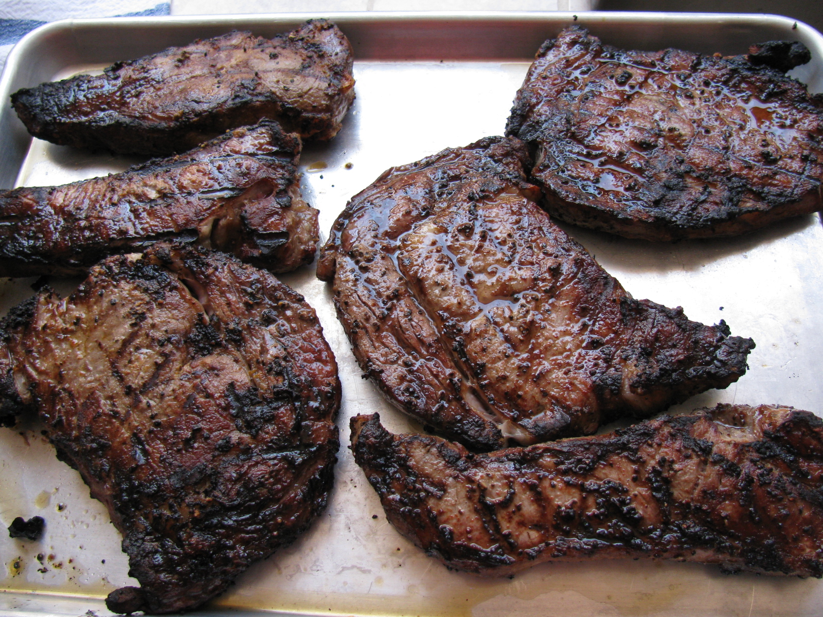
Hellfire strip steak with grilled corn on the cob
I had several strip and rib eye steaks taking up room in my freezer, and decided this would be a great time to stoke the Big Green Egg and cook ’em. Because anyone can direct grill steaks with the proper seasonings, I decided to do something different, and prepared the steaks using Steven Raichlen’s “Hellfire Steaks” recipe . The original recipe can be found here – and in Raichlen’s book, “How to Grill.”
http://www.primalgrill.org/recipe_details.asp?RecipeID=143&EpisodeID=19
I thought this crust – made of salt, pepper, powdered mustard and Tabasco sauce – would be very spicy, but I found out that this is not the case, and will add more Tabasco if I make this again. Here are some pictures of the steaks and some corn on the cob.


Maker Walt discussing something fascinating with Jeri Ellsworth, aka “Circuit Girl.” Photo by Tony KC6QHP
Here is a report on the 2013 Maker Faire by Tony Long (KC6QHP):
Another great Maker Faire is in the books, amateur microwave radio was well represented!
Thanks to the coordination efforts of Wayne KH6WZ, Brian W6BY, the 50 MHz and Up Group, the SBMS, and UC Davis, the “Not Your Grandpa’s Ham Radio 2” booth at the Maker Faire was a great success.
This year we shared a booth with UC Davis whose impressive student projects ranged from a radar demonstration, to video processing, audio sequencing, and mechatronics. Along with that, we had a 10/24 GHz SDR setup courtesy of Dennis W6DQ (on a big screen courtesy of Brian), some of Brian’s homebrew gear, Walt’s EM field demos and transceivers, and some of my stuff including a 10 GHz radio and beacon.
LA Times says that about 165,000 people were expected to attend this year, so at a minimum 10,000 people passed by our booth. Our raspy voices are an indicator that a great deal of talking was done! I personally interacted with a number of people who are really interested in amateur microwave radio and if even a fraction of them get involved or raise general awareness, I think it is a success.
Walt’s demos, owing in part to their elegant simplicity and visual nature attracted a lot of attention and interest. On Sunday night he took them to a post-fair get-together with the who’s who of the hardware hacking scene (Jeri Ellsworth, Ben Heckendorn, Diana Eng, Alan Yates and many many others). All were impressed!
Something I see very encouraging in the “maker” scene is a real interest in RF. This crowd includes a good deal of embedded systems engineers, talented software people, etc. There’s a real opportunity to make connections with this crowd and get more activity on the microwave bands.
As Software Defined Radios decrease in cost and become more open source, I predict massive interest in RF and likely in the microwave bands because of their large bandwidths. While they may not be interested in SSB mountaintop to mountaintop contesting (there will be those who are certainly), an increase in use of our bands will only help to further the cause of maintaining our spectrum to help further the state of the art.
I posted a gallery of pictures on Flickr: http://goo.gl/cAy3p
Tony KC6QHP”
Thanks for the report, Tony!
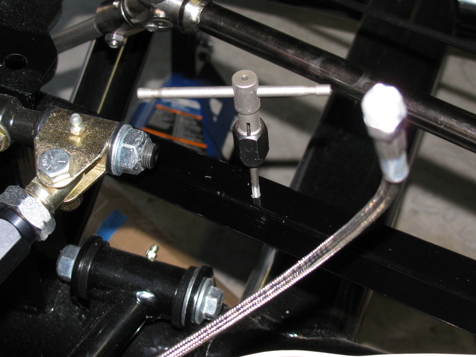
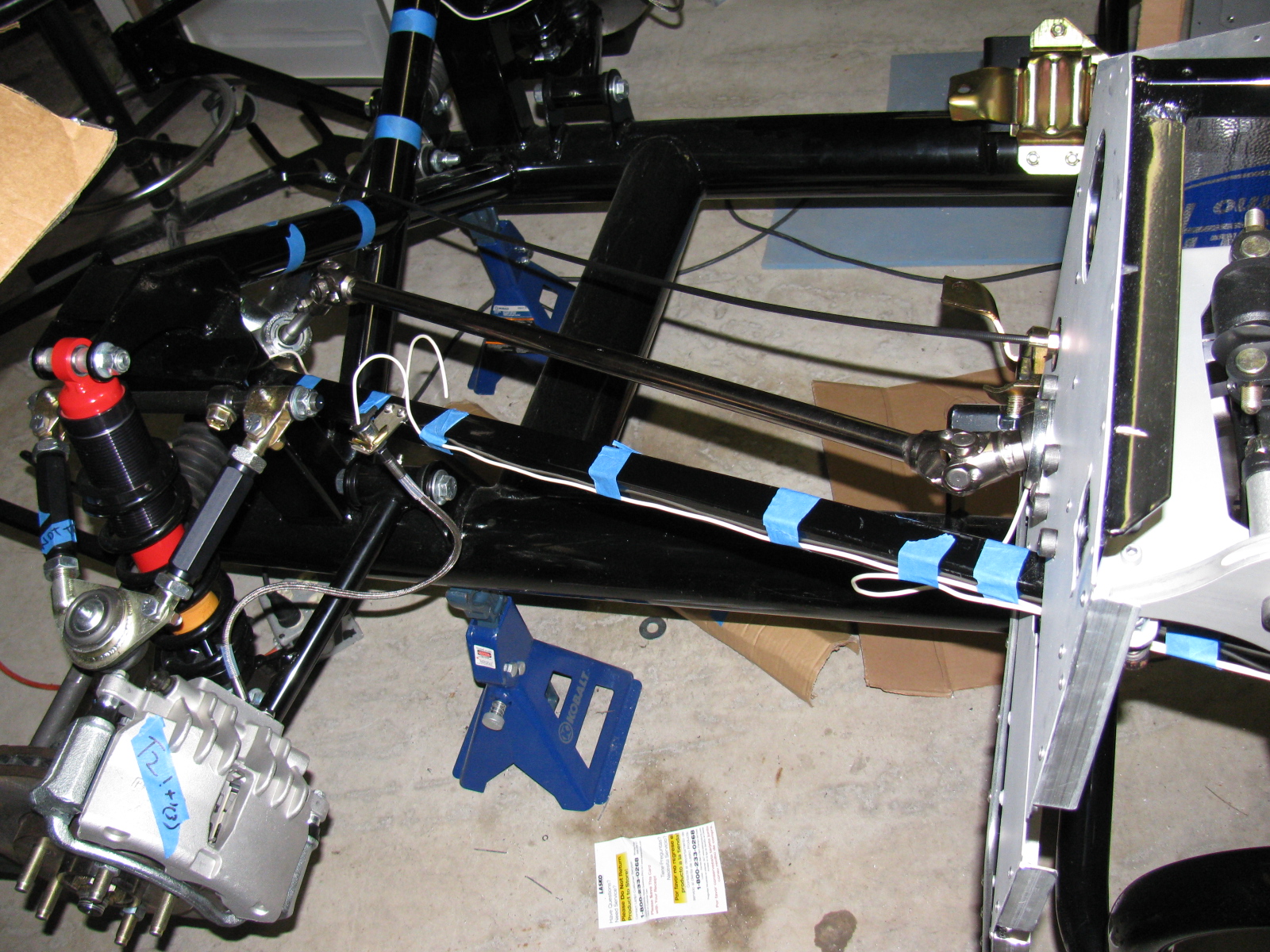
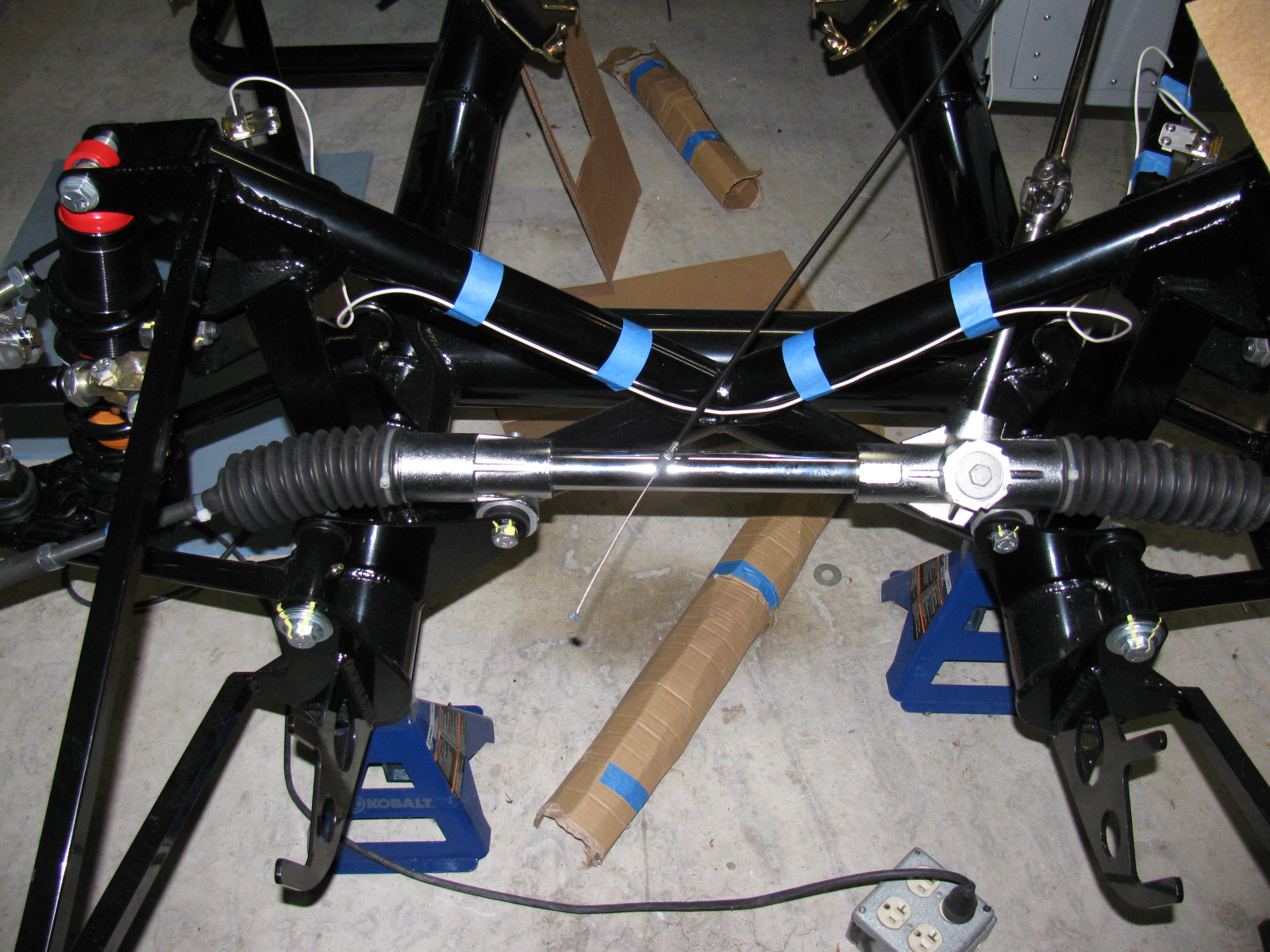
For some reason, things on the Coupe take much longer than I expect. I decided to practice running the brake lines today. I used some scrap number 12 wire, cut into five-foot lengths. The copper wire is much more flexible than the brake lines, but at least I can do a mock-up before I bend the real thing.
I am using the “FFR Type 65 Coupe build site,” by cbergquist1 on Flickr.com as a reference – click here to see Chris’ section on brake lines. http://www.flickr.com/photos/51103049@N00/sets/72157622122325431/
Just like Chris, I drilled and tapped holes for screws to mount the flex brake line mounts. I used 8-32 stainless steel button head screws. The Allen heads almost look like rivets.
Here are some pictures of my front brake line mock-up. . .


This is something weird. One of the mounting holes (on the left) was not punched out. I used an automatic center punch to knock the slug out.


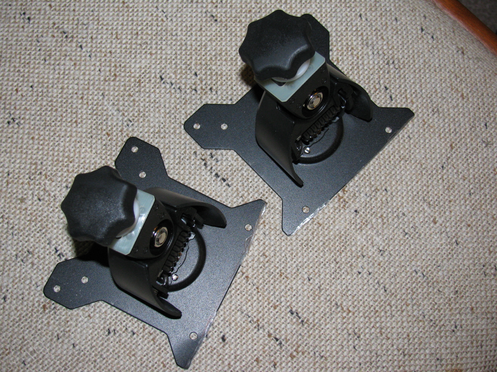
I took a time out to modify some monitor stand mounts for my office computer. The mounts were designed by monkeys, since they are useless and cannot be used out of the box. Actually, I should edit that statement, since I am not sure if the monitors or the monitor stands are wrong. In any case, some substantial cutting had to be done with my Dremel tool. I should have taken “before” and “after” pictures, but I wasn’t thinking. Here is a picture of the after-cutting operation. . . .

I wanted to try making baked potatoes on the BGE for over a year, and I finally tried it. This is based on the directions by The Naked Whiz, a ceramic cooker expert.
You can go here to see the original recipe. http://www.nakedwhiz.com/bakedpotato.htm
I cut the salt down to one-half cup and scrubbed the potatoes to make sure all traces of dirt were removed from the skin. I used my own “universal rub” for meats instead of the Dizzy Pig rub.
And this made me think about creating a rub for baked potatoes. Something like onion and pepper and garlic – sounds almost like the rub I use for Santa Maria Style tri-tip.
I cooked an entire 5 pound sack of russet potatoes for this trial.
The original procedure said to turn the spuds half-way through the cooking time. I just let them bake on their own and did not turn them.
Naked Whiz says to bake the potatoes for one hour – My potatoes took one hour plus 10 minutes. If you try this, test for doneness using a skewer – it should easily push into the potato.
These were excellent – the texture is very good. The skin has a smoky flavor, which could be another area to play with – add hickory chips next time? More baked potato experiments are in order.
Here are some pictures. . .