Archive for the ‘10 GHz and Up Contest’ Tag
The past weekend was a busy one indeed. I made some time to participate in the microwave contest, dragging my rig out to the bluff overlooking the Bolsa Chica Wetlands and then to El Segundo. The 10 GHz and Up Contest is unique, since it spans over two weekends, the first part is in mid-August and the second part near the end of September. This gives participants a chance to fix broken rigs and continue to add points to their scores.
To be honest, I was not prepared for this contest. I did not have any roving plans, my Prius was not modified to supply my 7 watt 10 GHz rig with power and my mobile radio was not programmed with any of the liaison / coordination frequencies. However, I managed to have some fun testing out my homemade 10 GHz (X-band) rig.
I noticed something during the contest: I was afraid of killing the 12V battery on the Prius, so I left the car on and “ready” during the entire contest. I turned off the air conditioner and the courtesy light. As with normal operation, the gasoline engine will only run when it is needed to charge the system, including the 300V (or whatever voltage it is) traction battery.
Since the rig draws 10 amps in transmit, and transmitting a continuous signal for “beaconing” so that other stations can find me is a routine practice in microwave contesting, I was worried that something might happen to the Prius power system.
However, the car seemed to be fine, and the rig was happy to run under full DC power, producing a clean signal and no “unlock” condition. The engine did start up and ran for less than one or two minutes at a time, and the engine is so quiet, sometimes I did not notice it was on.
Using the Prius as a power system worked out so well that I will eliminate my spare battery idea and mount a power connector on the battery box lid so I can use the DC to power station equipment for the next contest. I have a 100 Ah gel cell battery in a big plastic box that I usually use for radio contesting, so it is independent from the car power system – but I discovered the battery was dead and was not holding a charge when preparing for the Disaster Expo – that is another story. . .
Since I operated from these two locations before, I don’t have too many pictures of these places, but these will give you some idea of what operating a rover station in the 10 GHz contest is like. Well, not really.
My un-official score for about 5 hours of operating time is:
1900 QSO Points + 3341 Distance Points = 5241 Final Score
Best DX is 217 km, when I worked K6NKC and KC6UQH in DM12rr (East San Diego County) from El Segundo, DM03tw
The most fun and challenging contact happened to be my last contact. It was a two-way CW contact with WA6JBD in DM14go (not sure where), from the El Segundo water tower location.
Of the 29 total contacts made, 19 were unique callsigns
Here are some pictures . . .
-

-
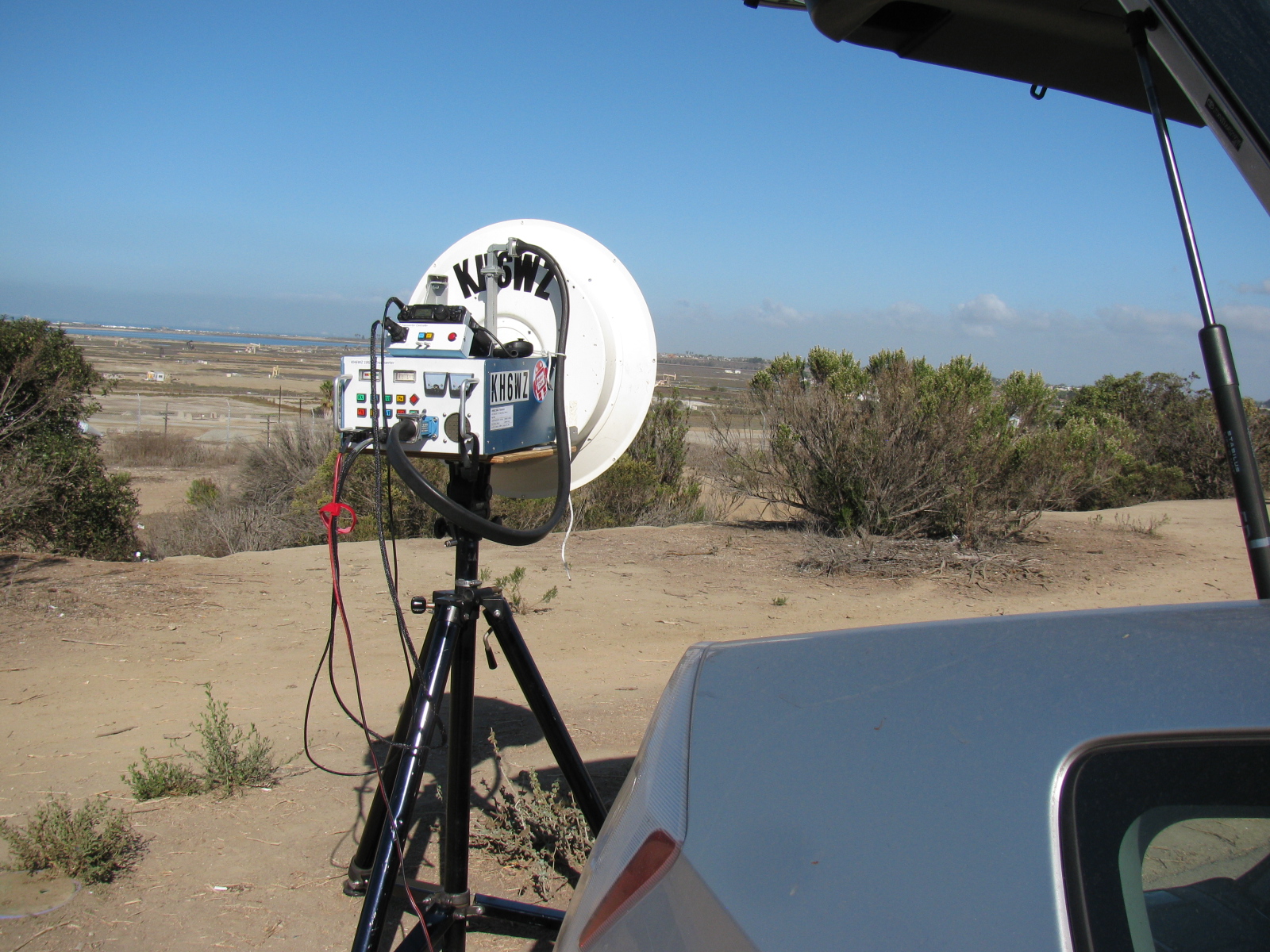
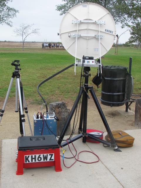
The first stop – KH6WZ in DM03xq – Huntington Beach, CA
-

-
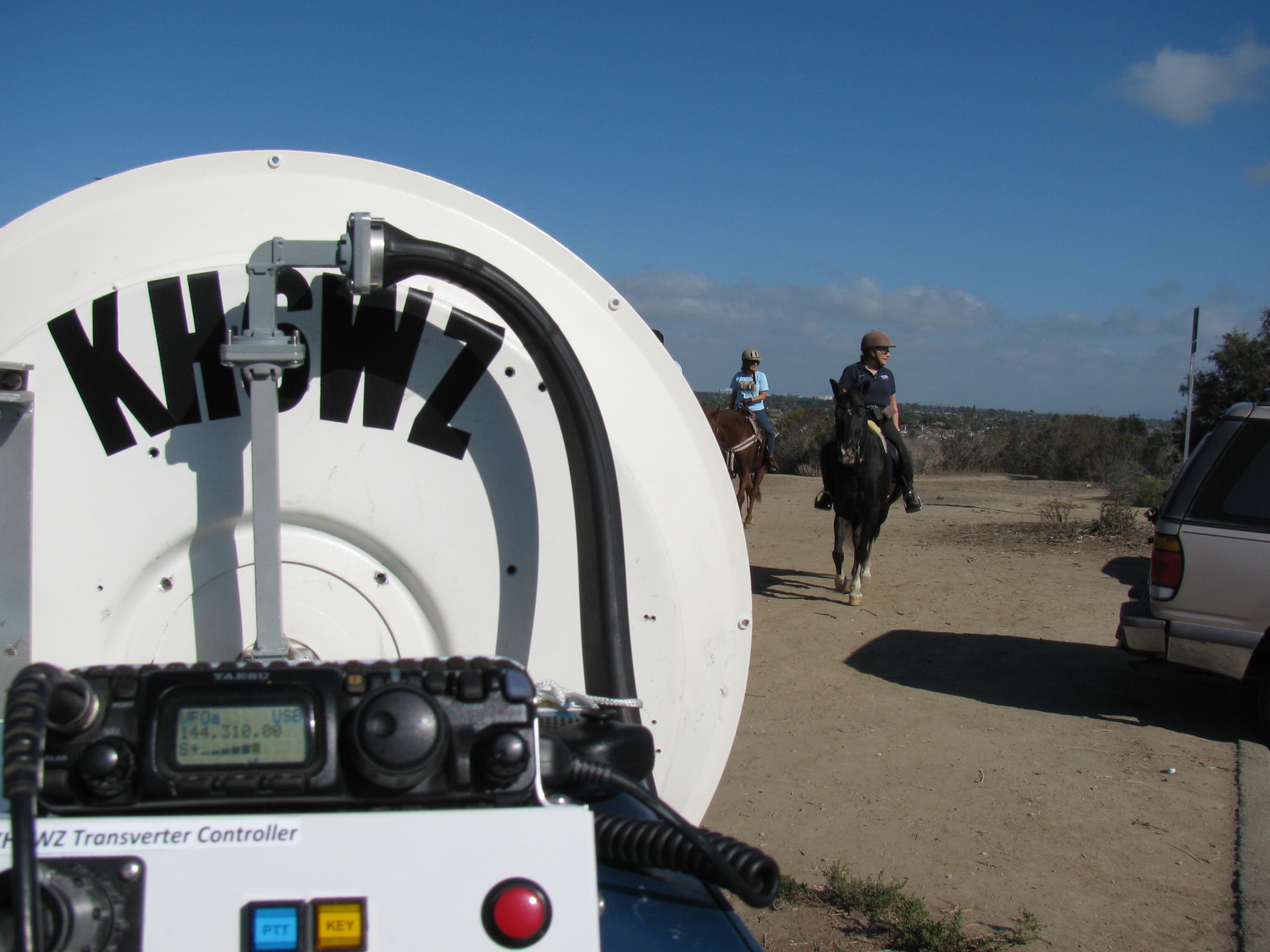
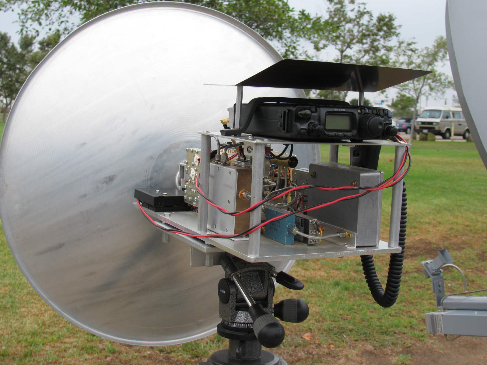
Some human as well as four-legged visitors to the Huntington Beach location. Take a look at the FT-817 S-meter and notice how the N6CA beacon (Frazier Mt., DM04ms) is booming in.
-

-
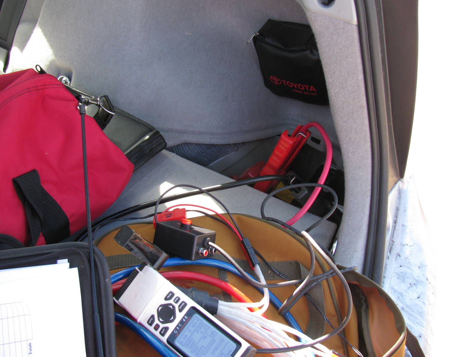
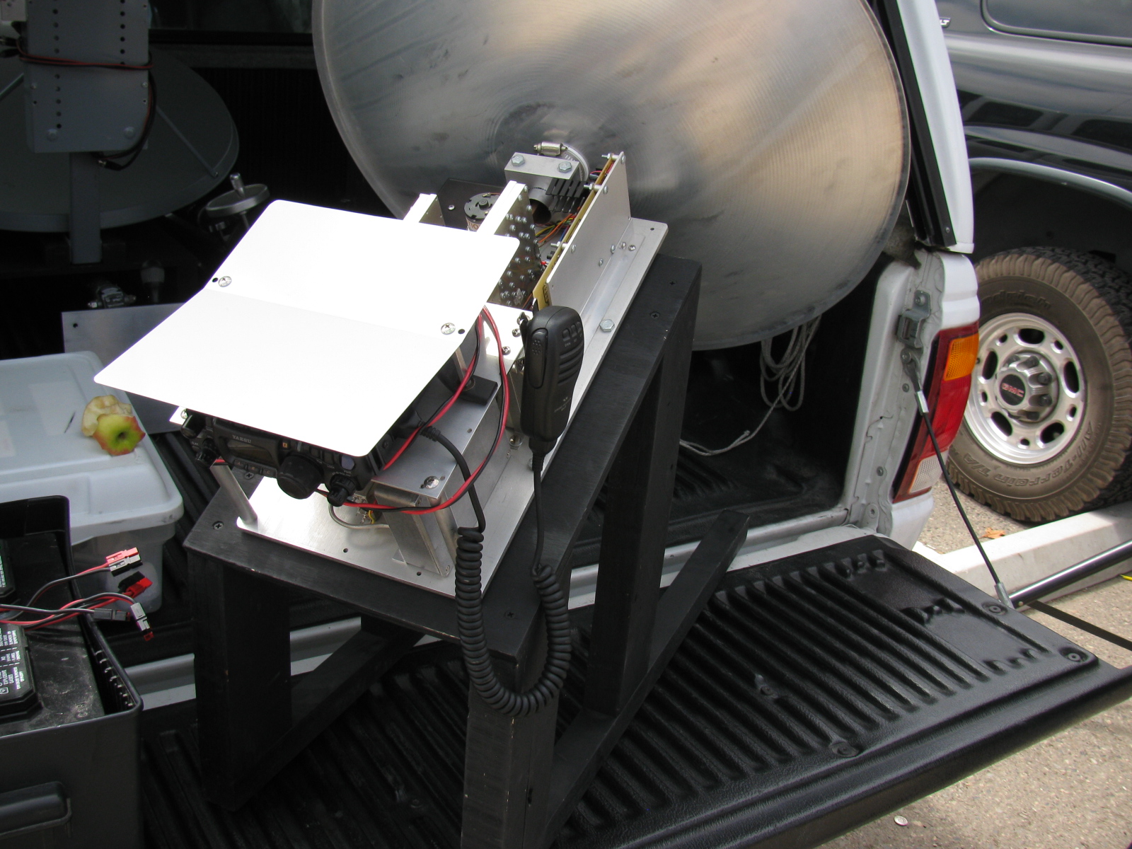
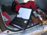
Battery jumper cables clipped onto the little 12V gel-cell in the back of the Prius supplied power to the station, which draws about 10 amps on transmit.
-
-
I really need to do something about the operating position inside the Prius. Yaesu FT-60, old Garmin GPS and the log sheets thrown in the back of the car.
-

-
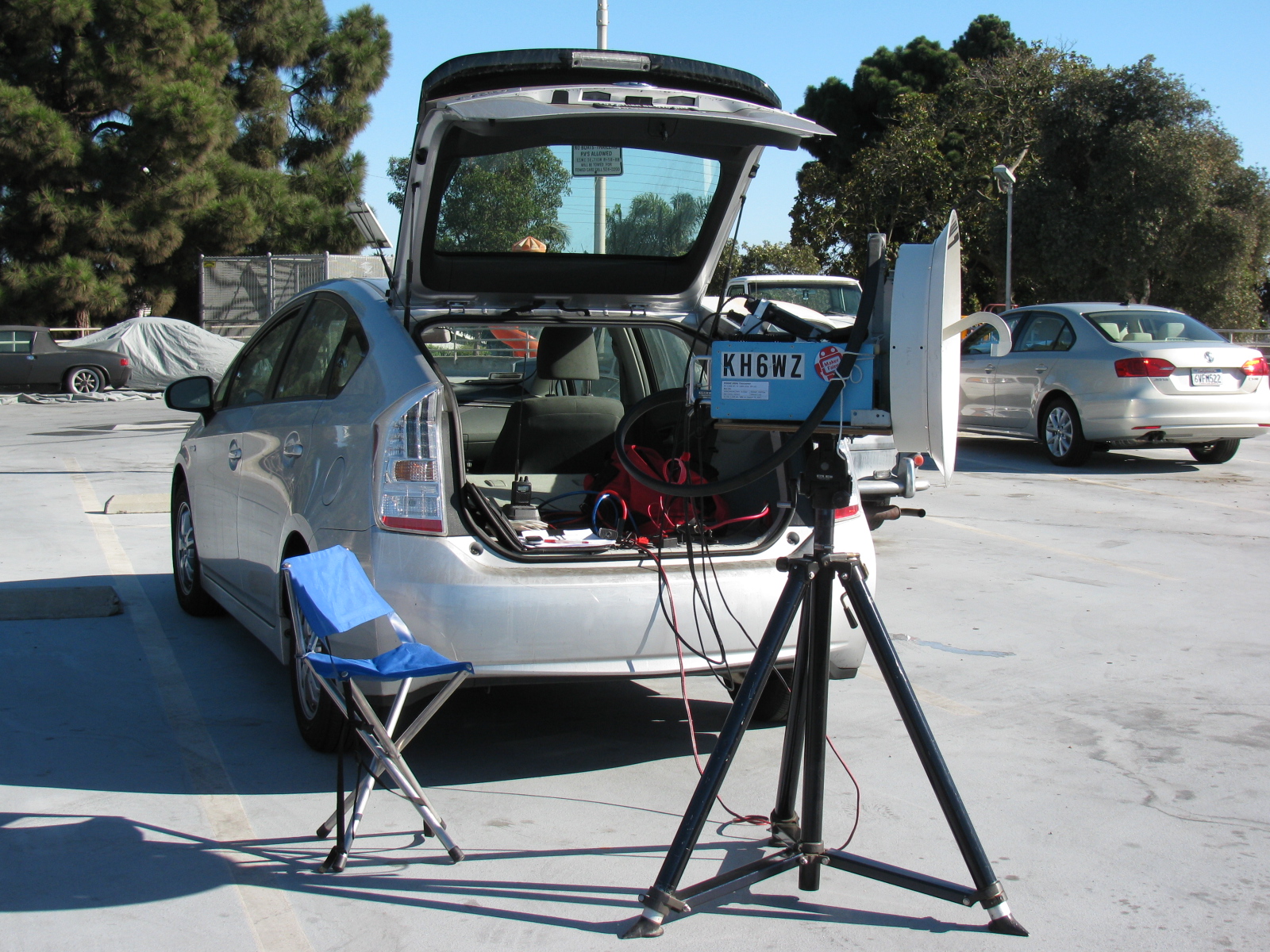
This is the second of two stops on contest Sunday. El Segundo, DM03tw. This is the top of a parking structure for a park, for some reason I never took note of the name. It is easy to find, just look for the water tower.
-

-
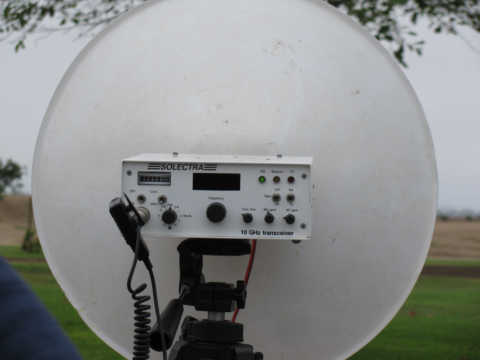
The KH6WZ station at DM03tw. The camping chair is more comfortable than it looks.

APRS display of the KH6WZ-5 location beacon at the 2013 OC Mini Maker Faire at UCI. Notice the beacon message at the top of the screen capture includes the URL of the event – a great publicity tool!
This past weekend, the second OC Mini Maker Faire happened. And it just so happens to be the second running of my ham radio demonstration called, “Not Your Grandpa’s Ham Radio (2)!” This is my continuing mission to remind people of two things:
First, “The Maker Movement” is nothing new, Amateur Radio operators have been doing this for a almost a century, and nearly 2 million people worldwide are involved in ham radio in some way.
Second, Ham radio is not necessarily an old man’s hobby where weird guys talk to strangers from garages and basements. We are skilled wireless communicators and use today’s technology, from GPS and microprocessors to lasers and microwave frequency linking.
This time I added static and working displays of my various APRS beacons (KH6WZ, KH6WZ-5, and others). I programmed the OC Mini Maker Faire’s URL to the beacon message so people can take a look at what was happening – an excellent publicity tool!
I also planned on making some 10 GHz contacts with my rig, since this was also the same weekend as the ARRL 10 GHz and Up Contest. The transverter covers were removed so people can see the system’s guts.
Based on previous experience at the Discovery Science Center “Meet the Makers” event, I demonstrated radio wave polarization- horizontal vs vertical – with my rig and the microwave strength meter.
Since I had plenty of space, I shared my booth with a company that makes interesting computer and microprocessor related items. This may sound trivial, until you realize this company is run by these three young guys . . .
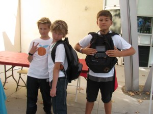
Huxley, Max and Ethan showing one of their products called the SmartPac.
There seemed to be more people at this Faire, probably since not too many other events were happening nearby. The 405/605/22 freeway closure did not affect the MF, since it started after the event ended.
More than a dozen hams – either active or at least licensed – stopped by to visit. We talked about this event as well as the Bay Area Maker Faire, and what ham radio activities we are involved with.
One more thing: I met several guys from the San Diego area – they are finalizing the plans to have a Mini Maker Faire in the San Diego area – this is great news. Stay tuned and I will announce an update as soon as I hear something from the committee!
Here are some pictures from the event. I am already thinking of building some new displays for next year.
-
-
The 24-inch M/A-COM dish with the KH6WZ logo makes a pretty decent sign for the booth, eh?
-

-
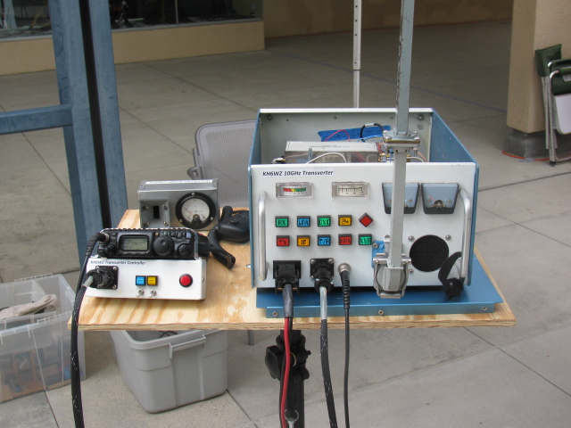
The KH6WZ 10 GHz transmitter-receiver unit on display at the Orange County Mini Maker Faire on the UCI campus
-

-
KH6WZ horn antenna and microwave field strength meter at the OC Mini Maker Faire 2013
-

-
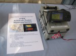
The KH6WZ APRS beacon (unit 1) at the OC Mini Maker Faire 2013. This was a static display unit to show components and construction.
-
-
KH6WZ-5 APRS beacon – active and sending position data at the 2013 OC Mini Maker Faire at UCI. The beacon message included the Faire’s URL.
-

-
This familiar unit makes an appearance at the Maker Faire. . .
-

-
The robot “Titan” was a crowd pleaser – it throws flying discs and comes to you for a refill.
-

-
Track Roamer robot at the OC Mini Maker Faire. Notice the Nerf gun. When you come to next year’s event, remember to wear a red shirt.
-
-
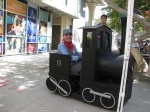
One of the “roving displays” at the OC Mini Maker Faire 2013.
-

-
Some ham visitors at the Orange County Mini Maker Faire 2013: Haliey, Michelle W5NYV, Paul KB5MU and John KJ6HZ.
-

-
Michelle W5NYV wearing her daughter’s alpha wave ears. The ears move and react to pulses from a sensor clipped to her left ear.
-

-
An unknown couple wearing Vocademy shirts. What a great slogan: Eat, Sleep, Make.

Microwave radio dishes used for ham (Amateur) radio communication.
The Orange County Mini Maker Faire is coming up (August 17 at UCI), so I added this intro to ham radio on the microwave bands. The Maker Fair coincides with the ARRL 10 GHz and Up Contest, and so, rather than missing the contest, I thought it would be fun to try working the contest from the Maker Faire. . . . .
Click here to view the presentation>>>> Microwaves: Not Just for Leftovers

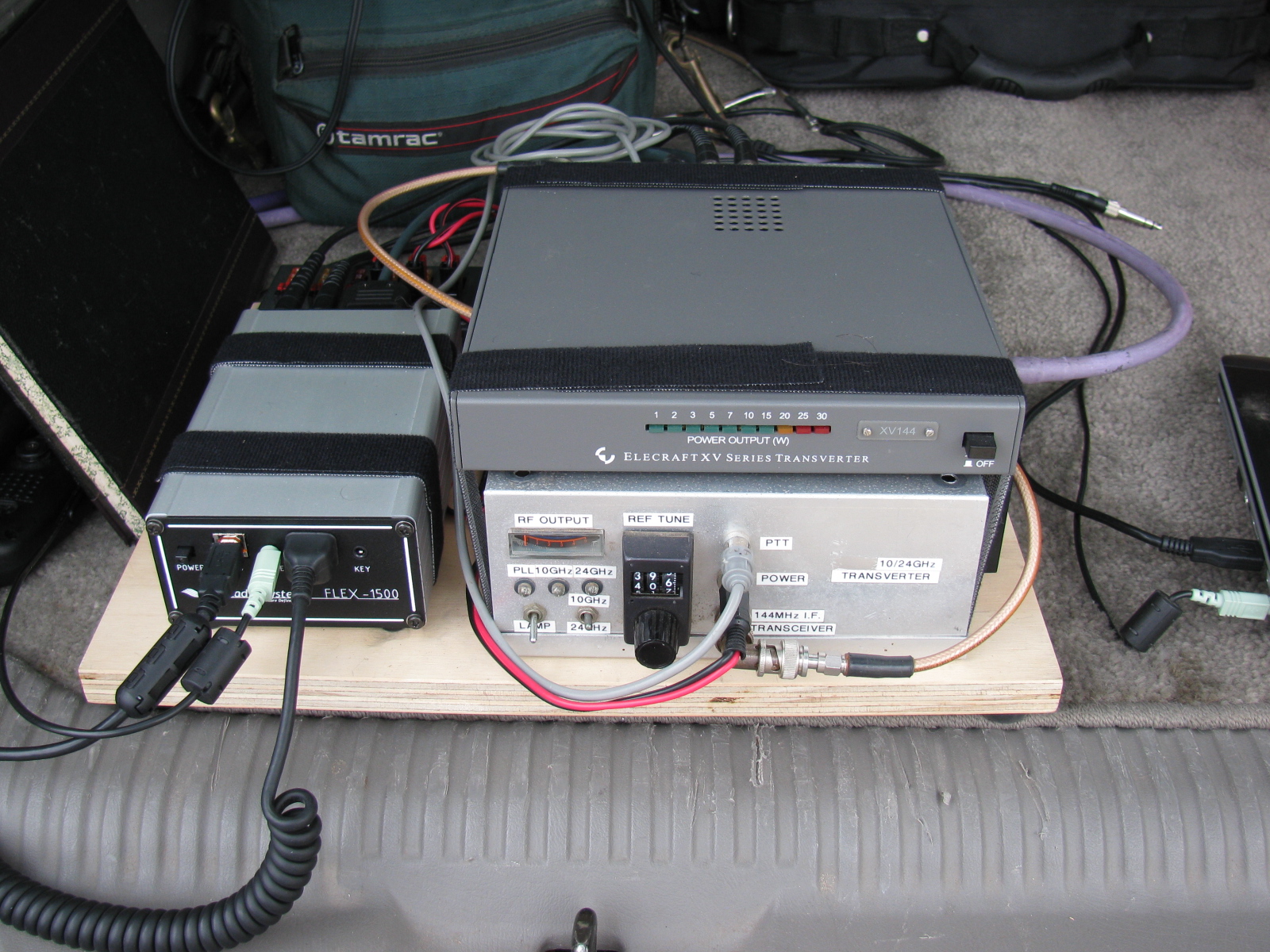
KH6WZ 10 GHz rig at a tune-up party
A presentation about record-breaking two-way ham radio contacts during the 2007 10 GHz and Up Contest
View the slide show in PDF >>>> XE2 to W6 in the 2007 10GHz and Up

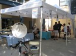
This past weekend, some of the active San Bernardino Microwave Society (SBMS) gathered at Fairview Park in the early morning to perform a field test of their microwave systems. Since I did not do anything with my rigs this past year, I decided to skip this field test, and take some pictures of any new more interesting rigs for this contest season.
Here are some pictures of the various station equipment SBMS club members built and tested that day . . .
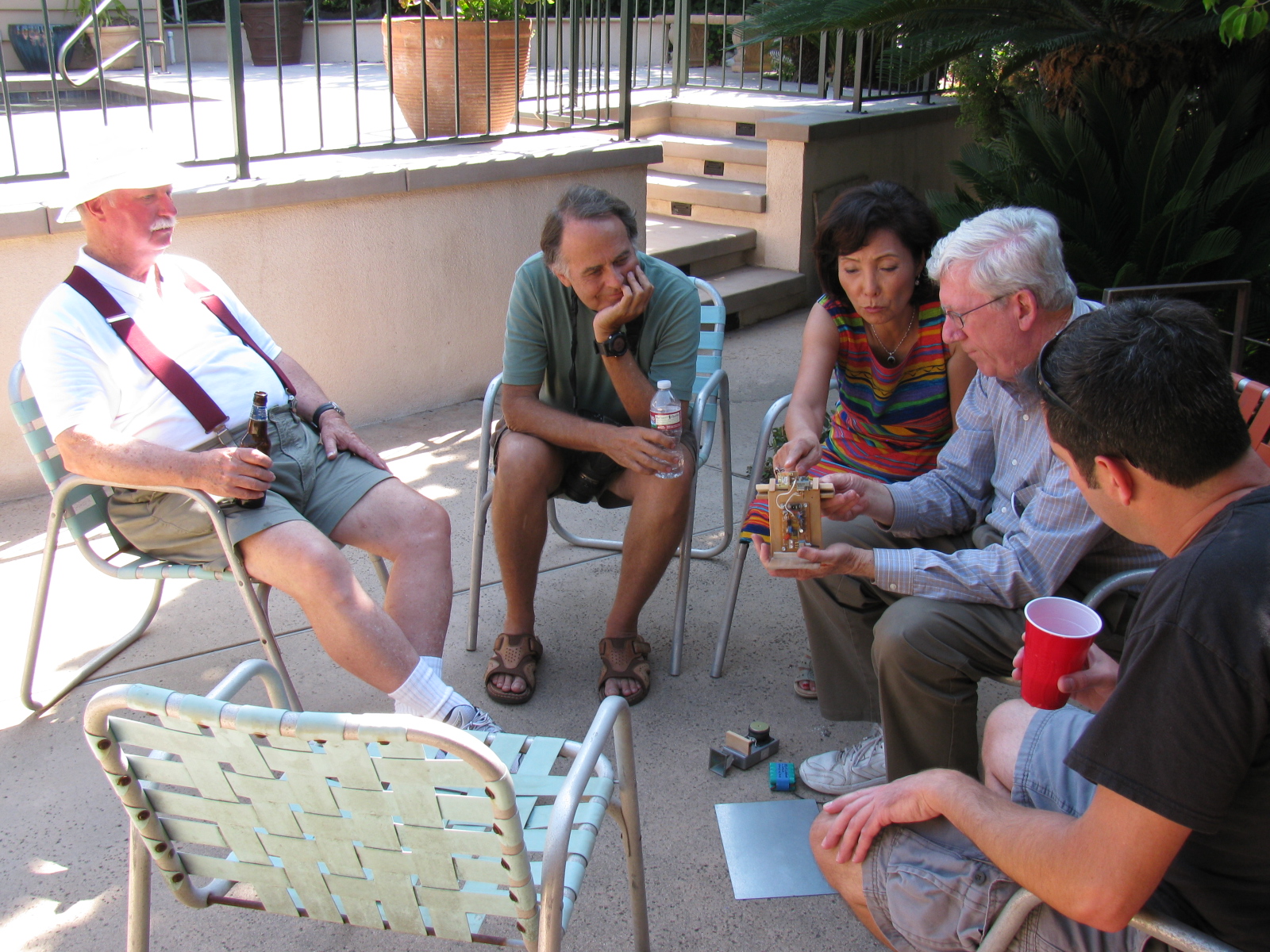
A post-Tune Up Party party and BBQ was held at Dennis W6DQ’s house. It was nice to relax and visit with the other SBMS members and enjoy some great BBQ chicken….. In the picture below, Walt, WALT explains one of his radio wave demonstrations to a captive audience… Watching and learning, from left to right are Bill Preston, KZ3G; Dan Slater, AG6HF and wife Sandy Slater; Walt, and Jason Sogolow, W6IEE.

If you are curious about the test setup, here is an article written by Kerry Banke, N6IZW, with some small edits by me:
Checking Microwave Radio Performance with a Simple ERP/MDS Test Unit
By Kerry Banke, N6IZW (Edited by Wayne Yoshida, KH6WZ)
Before heading for the hills with 10 GHz equipment around contest time, members of the San Diego Microwave Group (SDMG) and the San Bernardino Microwave Society (SBMS) check the Effective Radiated Power (ERP, transmit) and Minimum Discernible Signal (MDS, receive) with the simple setup described in this article. We hold the test sessions at the June and July meetings in preparation for the ARRL 10 GHz and Up Contest in August and September. The advantage to having two sessions is that it provides a second opportunity to verify improvements or allow participation if the first session is missed. The test unit works with both wide band and narrow-band radios.
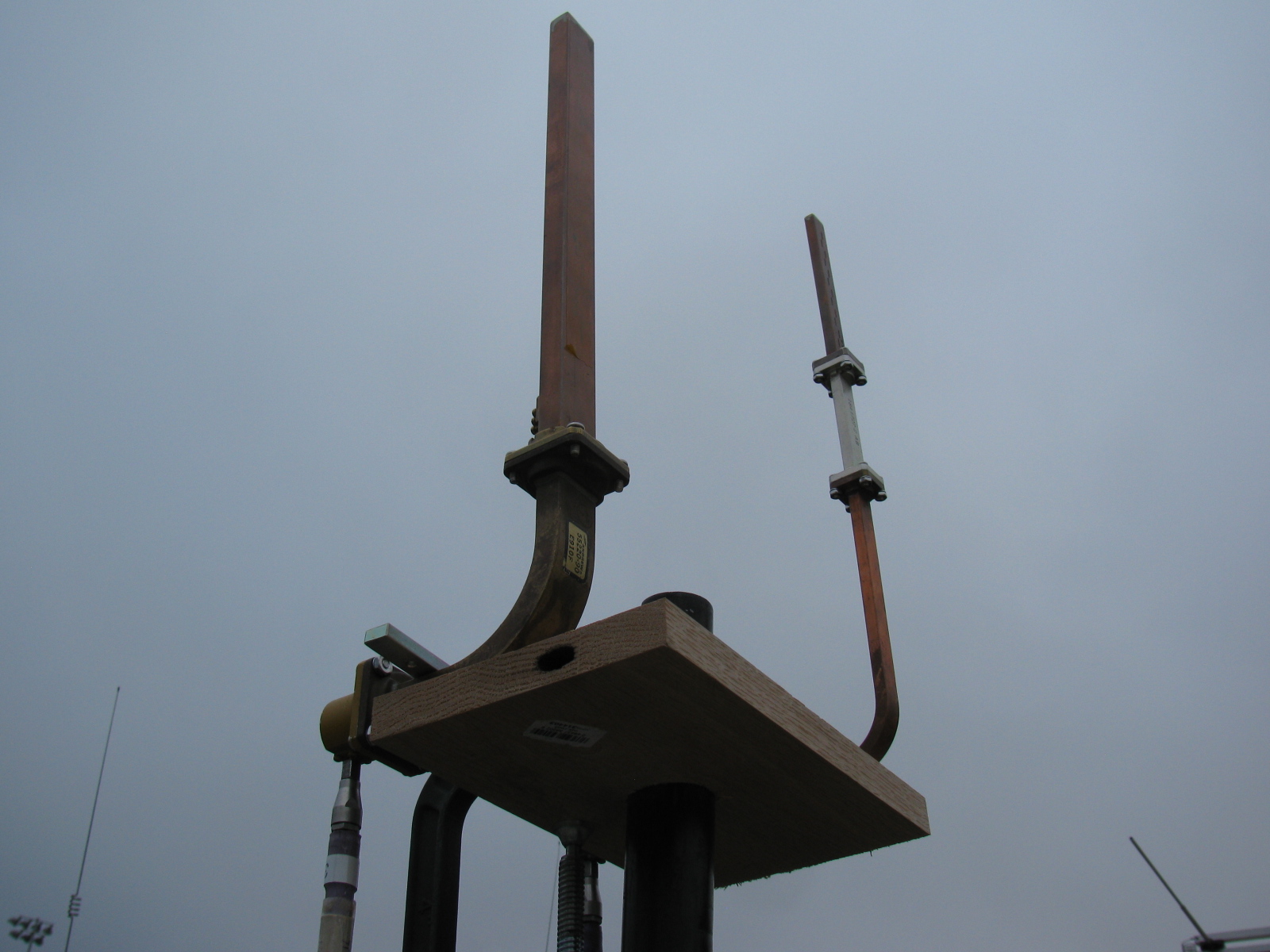
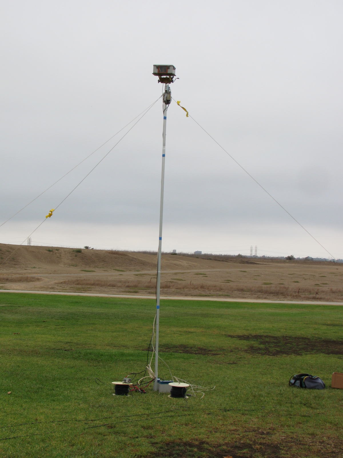
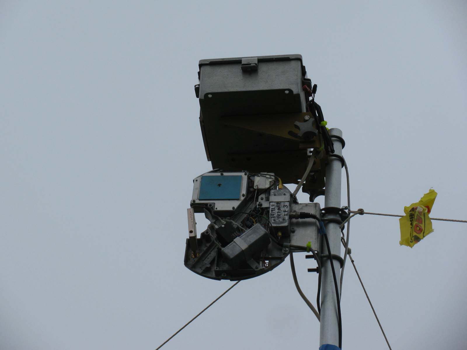
The Pole-Mounted Test Setup
The setup consists of a pole mounted X-Band converter unit connected by coax to a signal source (for MDS) and an amplifier/power meter located near the radios to be tested some 200-300 feet away. The MDS test must be performed first to align the radio antennas with that of the converter. A signal generator is connected to the IF coax and a suitable frequency (145 MHz) and power level (-40 dBm set to transmit an easily detectable carrier around 10368 MHz at the output of the converter.
MDS for Receive
Each participant adjusts their equipment and the system antenna for maximum signal as the power level of the signal generator is reduced to the point where it is no longer detectable by the radios. The level at which the signal can just be detected is considered the MDS.
ERP for Transmit
The ERP measurement is performed by connecting the IF coax to the amplifier and power meter. Each radio transmits one at a time and the power meter reading recorded. The variable attenuator is adjusted to keep the reading in a suitable power range for the power meter and amplifier. For the amplifier used, the maximum output power was about +10 dBm and the power meter range is about –20 to + 10 dBm so the attenuator was adjusted to keep the reading in the –20 to 0 dBm range.
The choice of the IF frequency for the converter depends on what is available for a 10 GHz local oscillator but needs to be low enough to keep the losses reasonable through hundreds of feet of coax. The amplifier gain and maximum output need to be based on the power meter characteristics. The signal generator needs to match the IF frequency chosen, have suitable stability for CW work (NB only), and have variable output (may be an external attenuator).
The converter consists of a Frequency West Brick as a 10,223 MHz local oscillator for a mixer used as an upconverter for MDS and down converter for ERP. The converter has a 13 dB horn antenna connected to the mixer RF port. Power is supplied by a 12V battery on the ground with a DC/DC converter supplying the required voltage for the local oscillator. The coax used is 300 feet of RG-59 which was readily available. No attempt to correct matching losses for the 75 ohm coax has been made. The loss of the coax and mixer as well as the amplifier gain was measured at the operating frequencies. It is not really necessary if only relative measurements are to be performed but it does allow a good comparison between measured and calculated values.
The results of the test are entered into a spreadsheet, which then calculates the ERP based on dish size in inches and estimated PA output of the radio under test. The distance in feet from the radios to the converter is input to the sheet, which then calculates the path loss in dB. For ERP, the sheet provides calculated ERP, measured ERP and the difference between them. For MDS at this time, only the signal generator level is recorded and is used for relative measurements.
Block diagrams for the 10 GHz and 24 GHz units are described in the PDFs below:
10 GHz ERP-MDS Block Diagram
24 GHz ERP – MDS Block Diagram
Intro to the MDS/ERP Event Results
(From an entry on the SBMS website on August 10, 2012)
These spreadsheets show the results of workshops/picnics where amateur microwave stations were compared on a unique test range for both transmitting and receiving performance. The test setup was developed by Kerry Banke, N6IZW and has been used by the San Diego Microwave Group (SDMG) and the San Bernardino Microwave Society (SBMS) over the past few years. The test setup consists of a remote TX/RX transmitter/sensor unit installed on a pole about 15 ft. high at a distance of approximately 220 ft. from the stations being tested.
The remote transmitter produces a stable signal on the operating frequency, such as 10368 MHz. Operators tune this in with their rigs and peak their antennas. The signal is then reduced in level until barely discernible (MDS). That level is logged. The operator then transmits with maximum CW power and the RX sensor power level is logged. The spreadsheet is used with the logged data and with data on each rigs claimed antenna size and transmit power to allow comparison of measured versus expected performance.
The results have been useful, not from an absolute basis, but by allowing operators to compare their rig’s results against other amateur’s rigs having similar TX, RX, and antenna characteristics. Any major performance differences between systems can help focus on problems that can be solved before upcoming contest events.
In past events, operators have discovered problems with relays, cables, connectors and even non-functioning power supplies.
Interpreting Results
Receive (MDS) performance is shown in the column marked “MDS Gen dBm.” You want the largest negative value compared to other stations having the same size or performance antenna on that frequency band.
In the last column marked “Meas-Calc,” transmit ERP performance is shown. A zero means that the ERP came out exactly as expected given the claimed transmitter power and antenna gain. A positive number indicates an ERP that is better than expected by that many dB. A negative number indicates system performance measures worse than expected.
Here are some results over the past years – 2013 results added!
TuneUp2013
SDMG ERP-MDS-2013 Results
TuneUp-2012
TuneUp-2011
TuneUp-2010
TuneUp-2009
Tune-Up-2008
TuneUp-2007
TuneUp-2006
TuneUp-2005
TuneUp-2004
TuneUp-2003
TuneUp-2002
TuneUp-2001
TuneUp-2000